Mechanical Installation Manual (450, 525, 600)
Seakeeper Ride | Mechanical Installation Manual (450, 525, 600)
1. Introduction
Updated 11/10/25
This document is intended to give details and guidance to a boat builder or equipment installer on the proper procedure for the installation of the Seakeeper Ride system.
Because of the quantity of parts and careful installation requirements, set aside a clean, well-ventilated workspace, take inventory of necessary tools and parts, and review the entirety of this manual before setting to work. To gain a broad understanding of the installation process, read the Installation Overview.
The instructions in this manual should be repeated for both the port and starboard Controllers.
Note: Scan the QR code below to access Seakeeper Ride BILT 3D instructions.


WARNING: You must read and follow all instructions before installing and using the Seakeeper Ride system.
Note: All torque values are in-lbs NOT ft-lbs!
2. Safety Notices
2.1 Stability
This system is not intended, nor should it be expected, to provide underway dynamic stability beyond the limits of the hull itself. It is up to the captain of the vessel to ensure that the hull is maintained and operated in a safe manner, within the limits defined by the boat manufacturer.
Seakeeper Ride is not designed or recommended for vessels capable of meeting or exceeding speeds greater than 80 miles per hour (mph) (69.5 kts), and the system’s controls will restrict deployment entirely when operating at those speeds. The system is not a substitute for adequate hull stability and will not prevent instabilities like those caused by improper boat operation at high speeds. Neglecting to adhere to this recommendation may result in system detachment from the boat. Seakeeper Ride’s standard warranty excludes coverage for system damage attributable to operation at speeds of 80 MPH and greater.
2.2. Forces Applied to Hull
While underway, the Controllers transfer high forces at each of the mounting locations. Careful consideration should be given to the transom strength and condition to ensure it can hold the loads created by the Controllers.
For aluminum hulls, verify first the aluminum boat transom structure can withstand fast, repeated, and high forces created by the Seakeeper Ride Controllers during use before applying to the mounting surface.
Note: The approved two-part adhesive is the structural bond between hull and Controller, therefore, if an aluminum sheathing protects the transom structure of the vessel, then the load must be transferred from the sheathing to the transom structure on these installs.
2.3. Installation Personnel
It is imperative that the installer is familiar with bonding using high-strength adhesives to marine structures and has thoroughly inspected the transom where the Controllers are mounted to ensure it can withstand the loads the Controllers create while deployed at speed. If the installer has any doubt about the ability of the transom to support the loads, they should contact a licensed naval architect or marine engineer to do a structural analysis.
The installer must review the full installation manual and associated drawings prior to installation to ensure the installation procedure is fully understood.
FAILURE TO FOLLOW THESE INSTRUCTIONS MAY LEAD TO IMPROPER INSTALLATION AND FAILURE OF THE SEAKEEPER RIDE SYSTEM TO OPERATE AS INTENDED.
IMPORTANT! Installation of the Seakeeper Ride system requires knowledge and experience in marine alterations, including drilling and grinding fiberglass or other boat hull material, applying high-strength adhesives, ability to inspect installation locations for fitment and potential obstructions, and marine electronics wiring. If the installer does not have knowledge and experience in these areas, the installer should contact a marine technician, engineer or naval architect for installation assistance.
2.4. Installation Tools
Use a properly calibrated torque wrench for final tightening of all bolts per this manual. Improper torque application to fasteners may cause damage to the system. Do not use power tools to install the bolts. This can cause galling and does not allow for the correct torque.
Note: All torque values are in-lbs NOT ft-lbs!
Apply the included Vibra-Tite 132 threadlocker to all fasters before installing to prevent galling and backing out.
3. Tools Needed
- Drill
- Dual Action Sander
- Oscillating Tool or Hacksaw
- Torque Wrench (20-80 in-lbs required)
- Socket Set (13 mm required)
- Phillips Head Screwdriver
- Hex Bit Sockets (2.5, 4, 5 & 6 mm required)
- Hex Wrenches (Allen Keys) (2.5, 5 & 6 mm required)
- Adjustable Wrench
- Squeegee, Putty Knife, or Tongue Depressor
- Digital Protractor
- 6-12 in. Straight Edge
- 3 ft Straight Edge
- Drill Bits or Hole Saw in Sizes 3/32 in. (2.4 mm), 9/64 in. (3.6 mm), 1/4 in. (6.4 mm) & 3/4 in. (19 mm)
- Approved Two-Part High Strength Adhesive (Methyl Methacrylate Adhesive or Epoxy) (See list below)
- For epoxies, Section 8.6 – Removing Gel Coat must be followed
- Two-Part Adhesive Dispense Gun (Check mixing ratio compatibility)
- Two-Part Adhesive Mixing Nozzles (Check mixing ratio compatibility)
- Marine Adhesive Sealant (3M 5200 is recommended)
- Masking Tape
- 60 Grit Sandpaper
- *High-Strength Threadlocker (Vibra-Tite 132 is recommended)
- Acetone or Denatured Alcohol
- Clean Gloves (recommended)
- Plain White Paper Towels
- Marker, Pen, or Pencil
*Vibra-Tite 132 will be included in the package. If an alternate threadlocker is used, a threadlocker activator/primer will likely be required for the threadlocker to cure properly with the stainless steel hardware.
Two-Part High Strength Adhesives
Approved adhesives and working times*:
- Methyl Methacrylate Adhesives (MMAs)
- Acralock SA10-35 (25-35 minute), SA10-40 (40-50 minute), SA10-45 (35-50 minute), SA10-60 (50-70 minute), SA10-75 (65-90 minute), SA10-100 (90-120 minute)
- Adhesivetech AT330 (18-32 minute)
- Crestabond M1- 60HV/2 (60 minute)
- Partite 7425 (25 minute)
- Plexus MA590 (90 minute)
- SciGrip SG300-40 (40 minute)
- Utiligrip MMA330 (18-32 minute)
- Epoxies (For epoxies, Section 8.6 – Removing Gel Coat must be followed)
- Araldite 2015-1 (45 minute)
- Pettit Flexpoxy (25 minute)
- West Systems Six10 (42 minute)
Adhesive, dispense guns, and solvent wipes can be purchased from the Seakeeper Partner center or your local and online retailers.

*Note:
- Working times listed above are the average window for applying, assembling, and adjusting when mounting the Wedge Pack with adhesive.
- Adhesives also have fixture times that must be honored when considering how long to wait before mounting the Actuator.
- Each adhesive has a full cure time or close to full cure, which must be met before any load is applied. After the installation is complete, before sea trialing the boat, wait at least the full cure time advertised by the adhesive manufacturer in the temperature during the install, or 24 hours, whichever is greater.
- Temperature will greatly affect all of the times mentioned above. Warmer temperatures reduce working time. Colder temperatures increase fixture time and cure time. (In very cold climates, the adhesive may need to cure for multiple days before sea trialing.)
- Refer to technical data sheets (TDS) and manufacturer recommendations for the particular adhesive being used.
Quantity:
| Controller Size | Minimum Adhesive Quantity (per boat) | Minimum Adhesive Quantity (per Transom Plate) |
| 450 mm | 900 ml | 450 ml |
| 525 mm | 1050 ml | 525 ml |
| 600 mm | 1200 ml | 600 ml |
Approved two-part adhesives come in multiple mixing ratios – 1:1, 2:1, or 10:1. Use the correct dispense gun and mixing nozzles for the adhesive type. Failure to do so will result in poor adhesion and will void the systems warranty.

WARNING: Check the adhesive being used to verify it is compatible with the hull material (epoxy resin fiberglass, polyester resin fiberglass, gel coat, etc). Some require a primer when used with certain materials. For example: Plexus primer must be used if performing an aluminum hull installation with Plexus MA590.
4. Inventory Parts
Please review all parts included before proceeding. The following figure and table describe all parts included in the assembly. Review parts and ensure all parts are present before starting the installation procedure.
- Blade
- Seal Plate
- Actuator
- Actuator Plate
- 3 Degree Wedge Plate
- 4 Degree Wedge Plate
- 5 Degree Wedge Plate
- Transom Plate
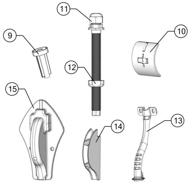
- Drill Guide Tube
- Drill Guide Follower
- Cable Gland Tube
- Cable Gland Nut
- Cable Support Guide
- Inner Cable Guide
- Outer Cable Guide

ATTENTION: DO NOT pickup the Actuator by the cable or allow it to hang by the cable. Doing so could compromise to the watertight seal of the Actuator and cause system malfunction.
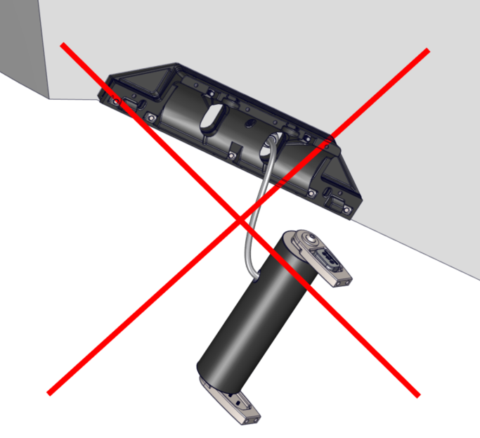
Table 1 – Mechanical Installation Hardware
| Wedge Pack Hardware | Positioning Screws | |||
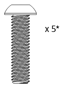 M8-1.25 x 30 mm Button Head Bolt | 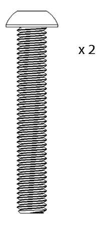 M8-1.25 x 50 mm Button Head Bolt | 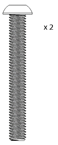 M8-1.25 x 60 mm Button Head Bolt | 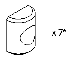 M8 Half Cylinder Washer 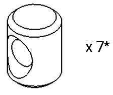 M8 Cylindrical Nut | 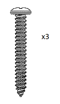 Phillips No. 8 x 1.25 in. Screw |
| Seal Plate Hardware | Blade Hardware | |||
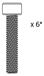 M6-1.0 x 30 mm Socket Head Cap Screw | 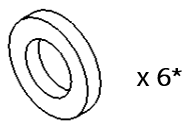 M6 Washer | 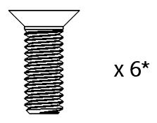 M6-1.0 x 16 mm Flat Head Socket Cap Screw | 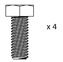 M8-1.25 x 20 mm Hex Head Screw | 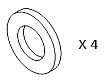 M8 Washer |
| Cable Routing Hardware | ||||
 Phillips No. 8 x 0.75 in. Screw |  Phillips No. 8 x 1.5 in. Screw | 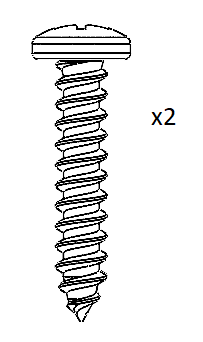 Phillips No. 10 x 1.0 in. Screw |
*Item count given for 450 mm and 525 mm systems. 600 mm systems will have two (2) additional pieces for this hardware type.
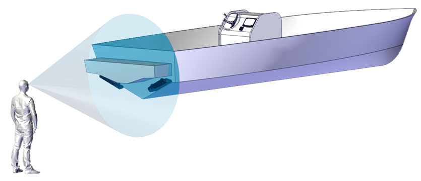
5. Identify Installation Location
Installation Location Introduction
The performance of the Seakeeper Ride system is a direct result of the proper mounting location of the Controllers. It is vital to abide by the criteria in the Seakeeper Ride Installation Location Guide to choose the optimal mounting point for the Controllers. Optional use of the Seakeeper Ride Controller Locator Tool will assist with locating where the Seakeeper Ride system will sit on the boat Hull and how much room it will take in order to install. See the Seakeeper Ride | Controller Locator Tool Manual for further instruction on use.
For new production installations, please consult with the Seakeeper Applications Engineering Team or a naval architect for the proper location of the Seakeeper Ride Controllers according to the hull shape, hull type, engine configuration, and other relevant application details.
For refit installations, please review the following sections to determine the ideal location for the Seakeeper Ride Installation.
Note: For refit Seakeeper Ride installations, if there are trim tabs or interceptor, they MUST be removed in order to install Seakeeper Ride.

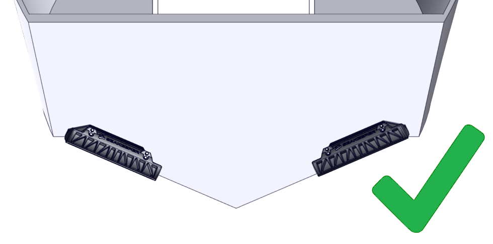
Figure 3 – Incorrect Seakeeper Ride Installation Between Trim Tabs vs. Correct Installation Near Chine
5.1. Longitudinal Location
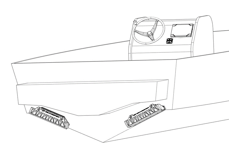
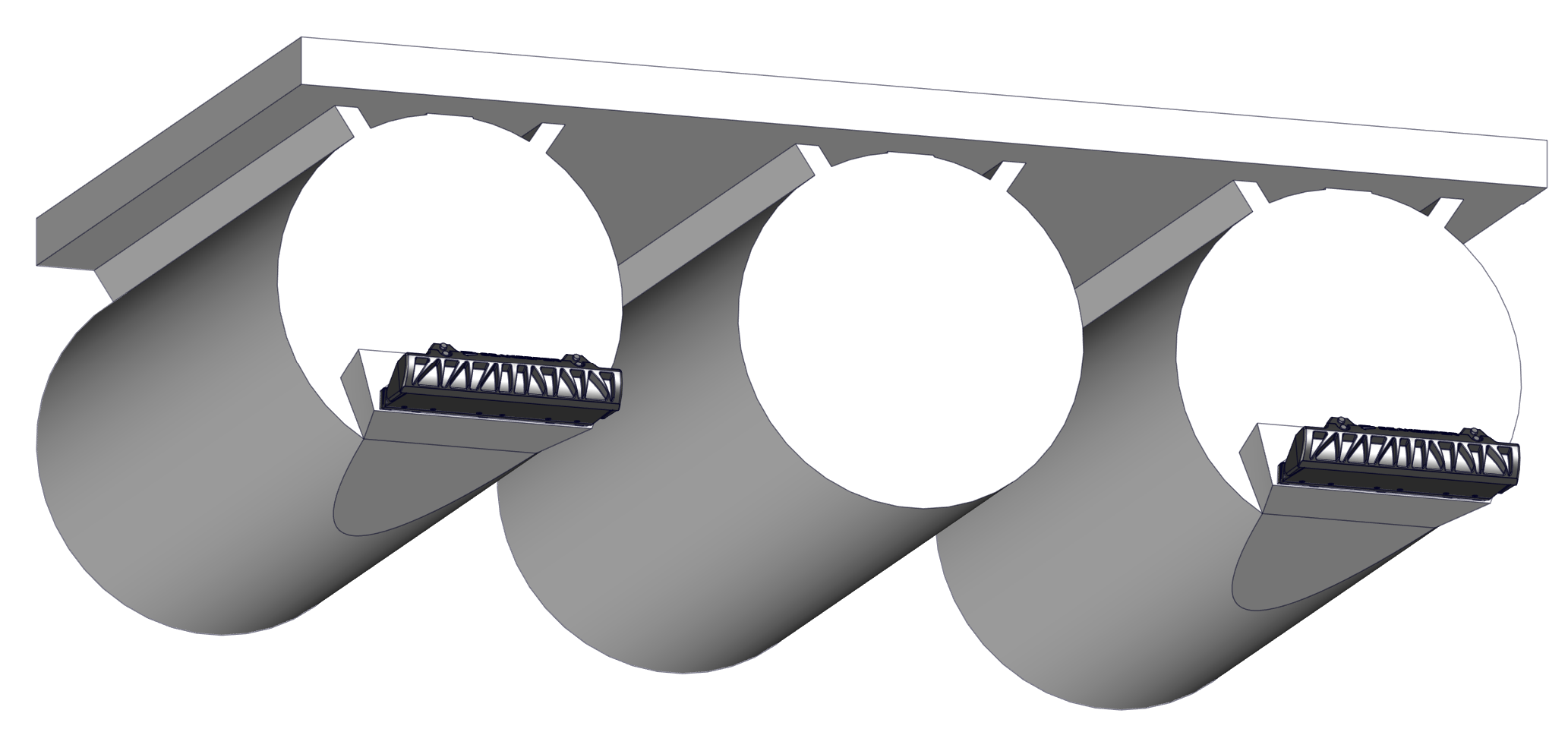
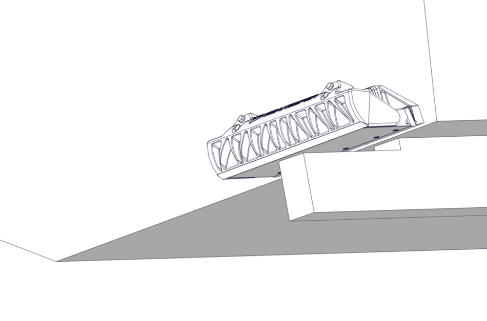
The Seakeeper Ride Controllers will be mounted to the transom, the approximately vertical surface at the aft end of the running surface, as shown in the figures below.


5.2. Vertical Location
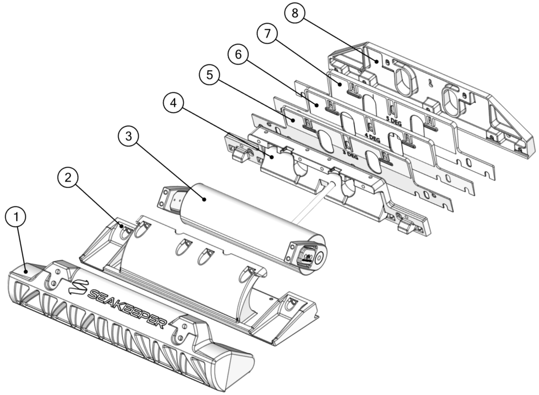
Seakeeper Ride’s Controllers must be mounted so that the bottom surface of the Seal Plate (Item Number 2 below) aligns with the hull bottom. The goal is to have the Seal Plate acting like an extension of the hull bottom. The Seal Plate’s location is determined by the Transom Plate (Item Number 8 below), which is affixed to the transom and adjusted up and down during installation to allow for fine-tuning the location.
1) Blade
2) Seal Plate
3) Rotary Actuator
4) Actuator Plate
5) 5 Degree Wedge Plate
6) 4 Degree Wedge Plate
7) 3 Degree Wedge Plate
8) Transom Plate
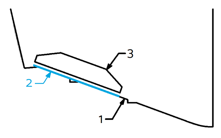
The Ride Reference Line (RRL) is a guide for where the bottom of the Controller should be when mounted. The RRL is a representation of the bottom edge of the transom where it meets the running surface of the hull. Because of the unique shapes of different hulls, the RRL may not follow the bottom edge of the hull exactly. The following examples give guidance on where the RRL should lie on hull bottoms that are not perfectly straight.
An example transom with an exaggerated radius is shown below. The RRL is shown in blue and is the intersection of the two straight edges.
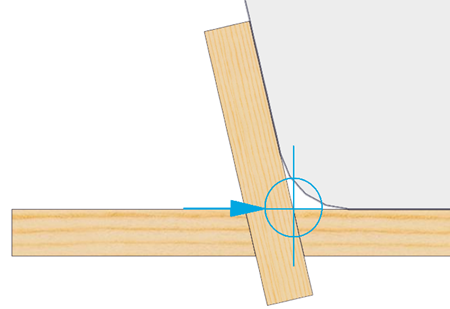
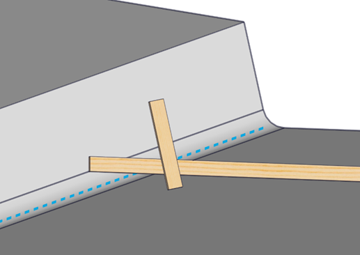
Figure 7 – Finding Reference Line with Straight Edges
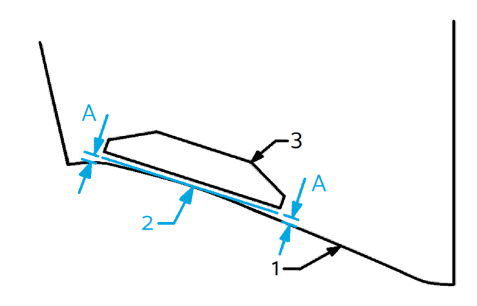
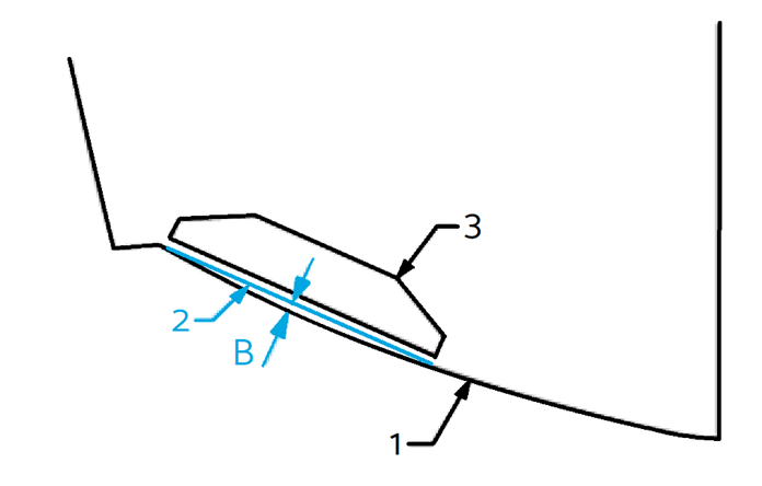
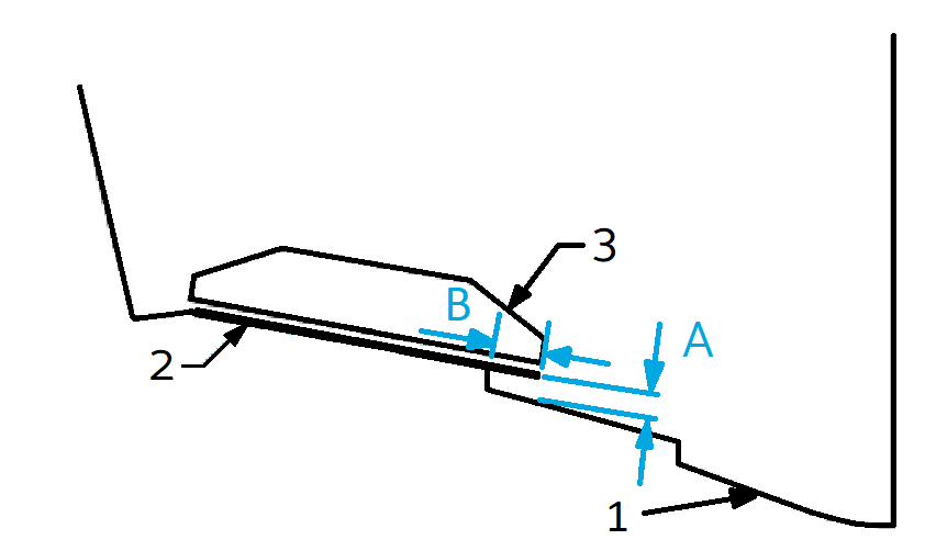
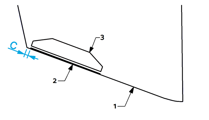
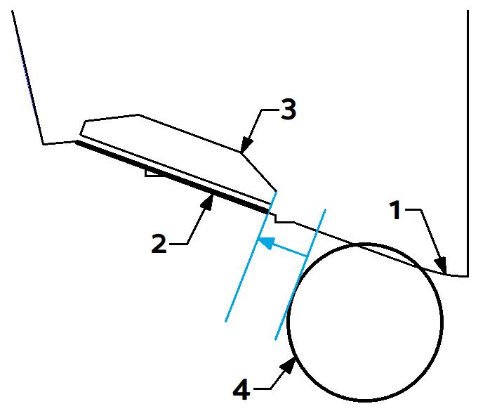
Figure 9 to Figure 12 in the following section show a view from the stern of the vessel looking toward the bow. Label 1 indicates the bottom of the hull, Label 2 indicates the RRL, and Label 3 indicates the outline of the Transom Plate.
Strakes
For hulls with lifting strakes or spray strakes, they can be ignored for the placement of the equipment and determination of the RRL. Please note, large strakes which extend all the way to the transom can reduce the authority of the Seakeeper Ride equipment. Terminating the strake at least 12 inches forward of Ride maintains full system authority.
Concave and Convex Deadrise
The Seal Plates (Item Number 2 in Figure 6) have a straight design. Some hulls may have curvature along the deadrise which will cause the Seal Plate to show gaps between the deadrise at either the ends or center of the plate. The following sections describe how to find the RRL in concave and convex deadrise hulls.
Concave Deadrise
For vessels with concave curvature, the Seal Plate should be mounted such that the center of the Seal Plate is flush to the hull bottom and the ends of the Seal Plate are equidistant from the hull bottom (measurement A in the figure below). Measurement A must be 0.5 in. or less. More curvature decreases Seakeeper Ride Authority. For vessels with concave curvature, the RRL is defined as the tangent to the hull bottom, shown by the blue line.
Convex Deadrise
For vessels with convex curvature, the ends of the Seal Plate should be mounted flush with the hull bottom with a gap between the center of the Seal Plate and the hull bottom (measurement B in the figure below). Measurement B must be 0.5 in. or less. More curvature decreases Seakeeper Ride Authority. For vessels with convex curvature, the RRL is defined as the straight line along the transom between inboard and outboard ends of the seal plate’s destination.
Variable Deadrise
Variable deadrise hulls are those where the running surface has breaks that run longitudinally. Generally, these hulls have decreasing deadrise angle in each successive panel moving outboard from centerline. Seakeeper Ride Controllers are capable of being mounted on variable deadrise hulls, so long as the following mounting conditions can be met:
- Distance from inboard edge of the Controller to the hull (Dimension A in the figure below) is 0.75 in. (19 mm) or less. This requirement only applies to vertical changes beneath the Controller.
- The portion of the Controller extending inboard of the deadrise break (Dimension B in the figure below) is 3 in. (76 mm) or less.
In hulls with a variable deadrise, the RRL is the highest portion of the deadrise that the Seakeeper Ride system will cover. See the figure below for this position. Because performance may degrade rapidly if these conditions are not met, please reach out to Seakeeper for guidance in this instance if a boat falls outside these parameters.
5.3. Beam-Wise Location
There are several hull features that should be considered when determining the location of the Controllers in a beam-wise orientation. As a general rule, the Controllers must be mounted as far outboard as possible, up to the chines (if the hull has chines).
ATTENTION: Mounting the Controllers towards the centerline of the boat reduces the leverage the system has on the boat and severely reduces roll performance.

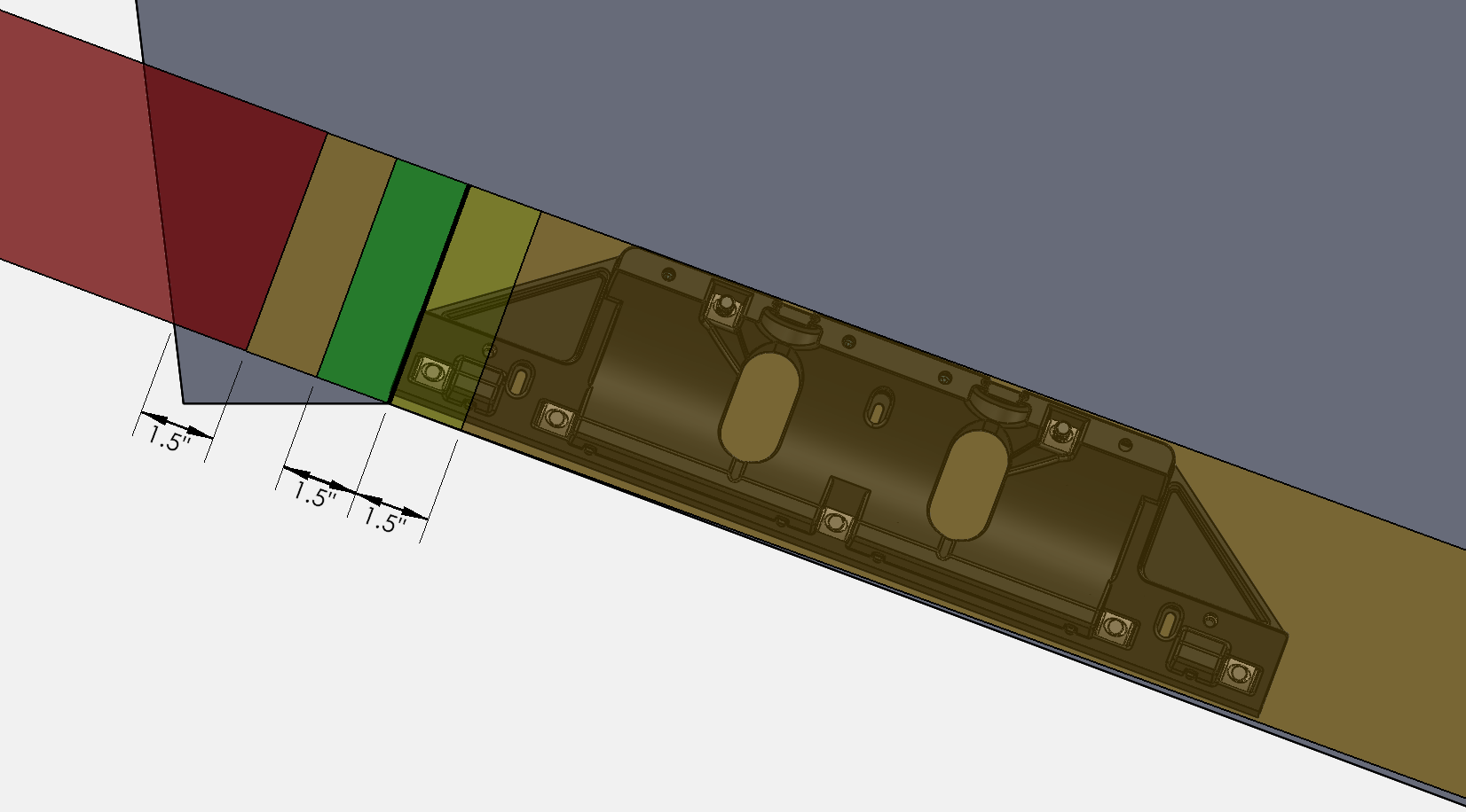
Chines
Based on the considerations of engine spacing and transom appendages, some installations will require the Controllers to extend outboard of the inboard edge of the chine. An overlap of the outboard chine of 1.5 in. (38 mm) is acceptable. For overlaps greater than 1.5 in. (38 mm), performance may degrade rapidly. The figure below illustrates placement of the outboard edge of the Controller with the following color code:
Green (Outboard of chine up to 1.5 in. (38 mm)) – Ideal
Yellow (Inboard of chine up to 1.5 in. (38 mm)) – Good
Orange (More than 1.5 in. (38 mm) from chine) – Acceptable*
Red (Overhanging Hull Side) – Unacceptable
*Controllers must NOT be mounted far enough inboard to reduce leverage, as outlined above.
Hull Side Spacing
It is possible to have an installation where the Controller is mounted too far outboard causing water flowing around the hull side to interfere with the Controller and substantially reduce performance.
To avoid this issue, the Controller should be mounted at least 1.5 in. (38 mm) inboard of the hull side, as shown below.
Engine Spacing
NOTE: Seakeeper has performed successful testing with Seakeeper Ride overlapping propellers significantly further than indicated below; however, because of the infinite variables (engine height, engine trim, engine longitudinal offset from Seakeeper Ride Controllers, propeller selection, propeller rotation, sea conditions, loading conditions, vessel characteristics, and more) which impact the interaction between Seakeeper Ride and propulsors, Seakeeper cannot provide more specialized guidance or blanket recommendation to install with more propeller overlap than indicated below. If the Builder, Owners, or Operators choose to install the Seakeeper Ride Controllers with more propeller overlap than indicated in the figure below, it may result in rpm/coolant fluctuation and/or engine faults. Please see the Operation Manual for additional detail on Seakeeper Ride’s potential impacts to propulsors.
Because the Controllers have the potential to change water flow into the boat’s propellers, the Controllers should be mounted as far from the propellers as possible. It is recommended that the inner edge of the Controller be mounted outboard of the diameter of the propeller tip (see the figure below). The line defining this instruction is the tangent line to the diameter of the propeller tip on the outboard side, perpendicular to the deadrise. Label 4 indicates the diameter of the propeller tip.
Note: Any obstructions preventing the installation of the Controllers or beyond the dimensions specified must be removed before continuing with the installation of Seakeeper Ride.
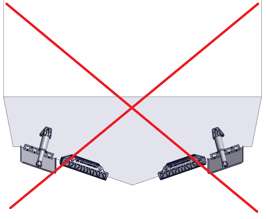
Pontoon Boats
The Seakeeper Ride Controllers should be mounted centered on the two outer pontoons regardless of whether it is a pontoon or tritoon boat. Mount the Controllers horizontal or parallel to the ground when viewed from the rear. Mount the Controllers parallel to the original bottom running surface of the pontoons when viewed from the side (see Figure 19).
Because pontoon boats generally do not have a flat transom surface and the running surface is essentially a very low radius convex deadrise (Convex Deadrise in Section 5.2.), modifications to the pontoons will almost certainly be necessary to create a flat mounting surface and relatively straight bottom with developed flow. Any modifications must be structural to withstand the extremely high loads Seakeeper Ride generates (Section 2.2. Forces Applied to the Hull). Modifications must be compatible with the original consturction of the pontoons.
Potential options for modifying pontoons to accept Seakeeper Ride include:
- Additive – Create a standoff or bracket with one side that matches the shape of the pontoon and gradually transitions to the shape of the Controller.
- Subtractive – Remove and replace material on the back and bottom of the pontoon at angles that create a gradual transition to the Controller’s width and straightness and create a flat mounting surface on the transom.
- Combination – Options 1 and 2 may be combined by cutting a flat transom and hull bottom with partial shape and flow transition and completing it with a bracket that is the correct size and distance to supply fully developed flow to the Controller. Combination modification example is shown in the figure above.
Important Notes:
- Running characteristic considerations – When making pontoon modifications, consider the permanent effect it will have on the running characteristics of the boat. Adding material will generally add buoyancy and bow down attitude. Removing material will generally remove buoyancy and add bow up attitude.
- Gradual Transition – Previous testing performed by Seakeeper suggests at least 12.0 in. (30.5 cm) for-aft for every 1.0 in. (2.5 cm) of height to ensure fully developed flow to the Controllers. In other words, at least a 12/1 slope is required when viewed from the side of the boat. Failure to transition gradually will result in substantially reduced performance.
- Transom Angle – The transom must be at an angle compatible with the Controller Wedge Pack adjustment limits (See Table 2 in Section 6.1.). The transom angle CANNOT be 90 degrees.
5.4. Overhead Clearance
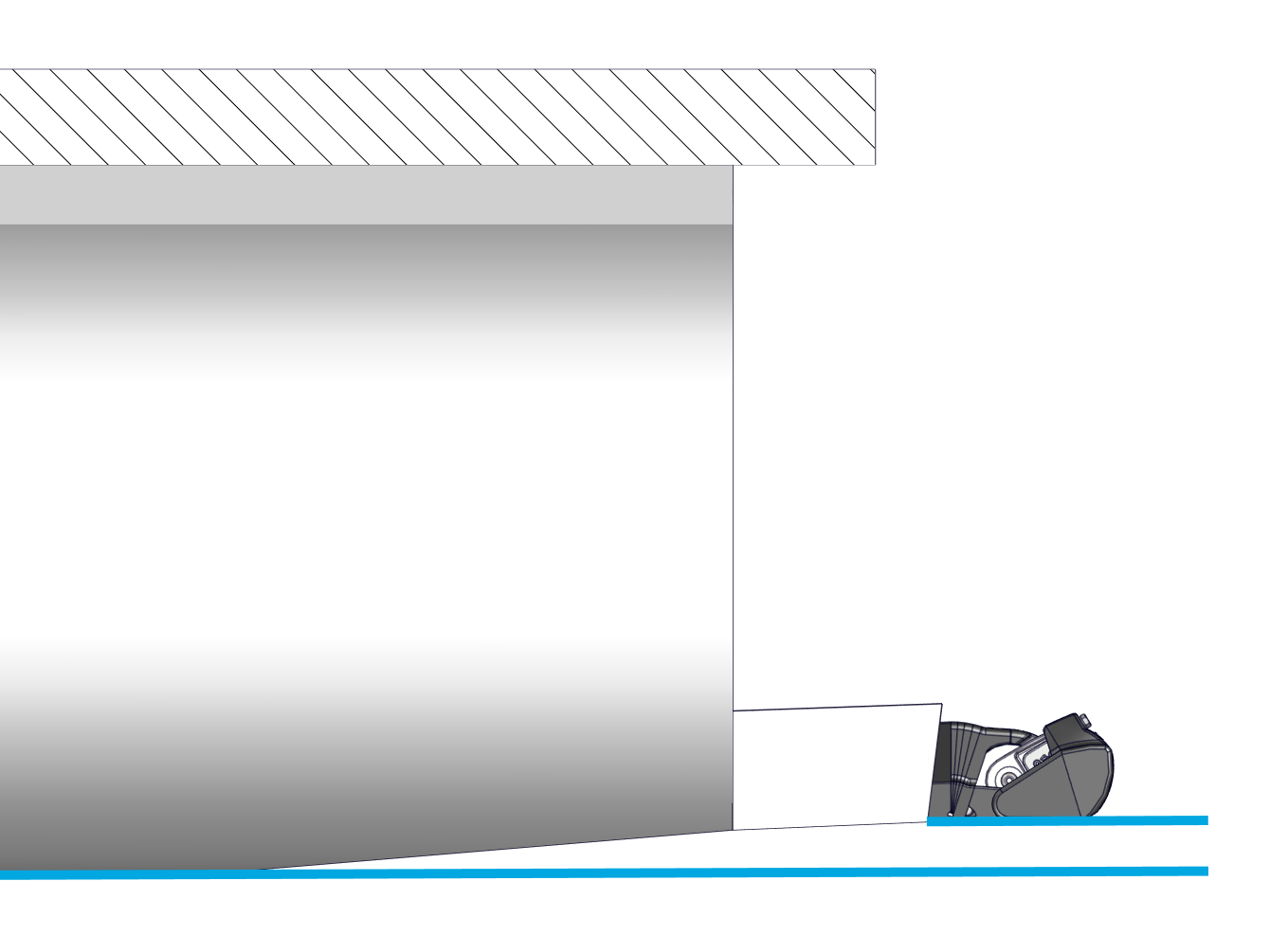
Because the Controllers are mounted externally on the hull, there may be some installations where space must be cleared to create room for the Controllers. There must be at least 5 in. (127 mm) of clearance between the aft most running surface and any surface above where the Controller will be placed (this includes any bracket or similar hardware that hangs over the Controller). The Controller will extend aft of the hull by 8 in. (203 mm).
5.5. Loading and Storage Details
The Controllers should not be installed where they will carry any load of the boat while on bunks (i.e. a trailer, storage rack, or fork truck). If there is concern with bunks loading the Controllers:
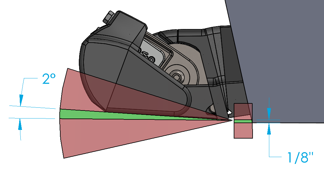
Mount Upward – Seakeeper Ride can be mounted up to 1/8 in. (3.2 mm) up from the bottom of the hull with negligible effect on system performance.
Angle Upward – Seakeeper Ride can be mounted up to two (2) degrees angled upward from the bottom of the hull with negligible effect on system performance.
One or both of these mounting tolerances may be used to keep Seakeeper Ride from contacting the bunks and increase the longevity of the system.
Seakeeper Ride will automatically retract the Blades when coming to a stop, meaning that they will be flush with the rest of the Controller and should not cause problems when placing the boat on bunks during normal operation in both Auto and Manual modes.
Setting Up the Trailer for Seakeeper Ride
Cut bunks short – If the bunks are too long, cut them to correspond with the end of the transom rather than extending aft.
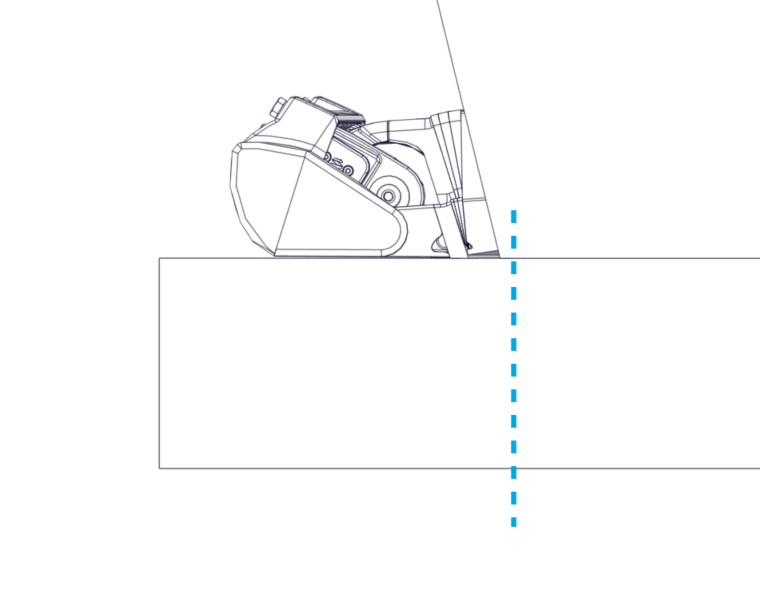
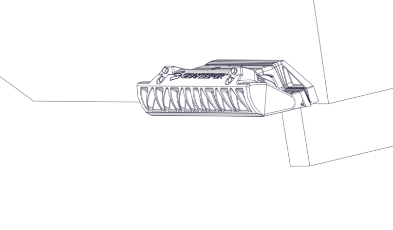
Figure 22 – Cutting Bunks Short
Cut bunks low – If the bunks cannot be cut shorter, bunks can be cut with a small recess below Seakeeper Ride to prevent excessive force on the Controller when going down the road.
Do Not Place Tie-Down Straps Across Seakeeper Ride – Consider moving straps to cleats or to a different tie down point.
5.6. Asymmetrical Details
Many boats are not perfectly symmetrical about the centerline, resulting in subtly different mounting locations and angles for each Controller. This is acceptable and may require different Wedge angles used for port and starboard Controllers. Following this guideline for the correct installation location will result in a proper installation even if there are asymmetries in the hull.
5.7. Cable Entry
In the final details of the installation, the cable that powers and drives the Controllers must pass through the transom of the hull. The location for cable penetration will be based on available access to the transom on the interior.
Concealed Cable Entry
Note: For concealed cable entry, the Cable Gland Tube must be inserted before mounting the Wedge Pack.
For concealed cable entry, route through either of the oval holes of the Transom Plate (highlighted in blue in the figure below). To utilize either location, you must be able to reach the hole from the inside to tighten the supplied cable gland and prevent water entering the hull.
As an example for internal routing, the figure below depicts a stringer shown with dotted lines that is preventing use of the inboard cable penetration. In this example, the outboard cable pass-through is available as indicated by the blue arrow. This can only be used if there is access on the interior side of the penetration.

Exposed Cable Entry
Locations outside the Transom Plate can be used as well. If the cable penetration location is below the waterline, the supplied cable gland must be used to ensure a watertight hull after the penetration.
This cable penetration method can be used in locations above the waterline as well.
Note: Supplied Cable Glands may be installed backwards with the grey cap facing outwards if there is no access to tighten the Cable Gland from inside the boat. If the Cable Gland is installed backwards, the Inner Cable Guide and Outer Cable Guide cannot be used. Ensure the proper amount of Marine Adhesive Sealant is used and rubber grommet is tightened on the Cable Gland, so water does not enter inside the boat.
Cable Lengths
In all cases, the supplied cable for the Controllers is limited to 10 ft (3 m). Carefully consider the cable routing and location of the Distribution Module to ensure both cables can connect to the Distribution Module.
6. Measure Transom Angle
Measure Transom Angle Introduction
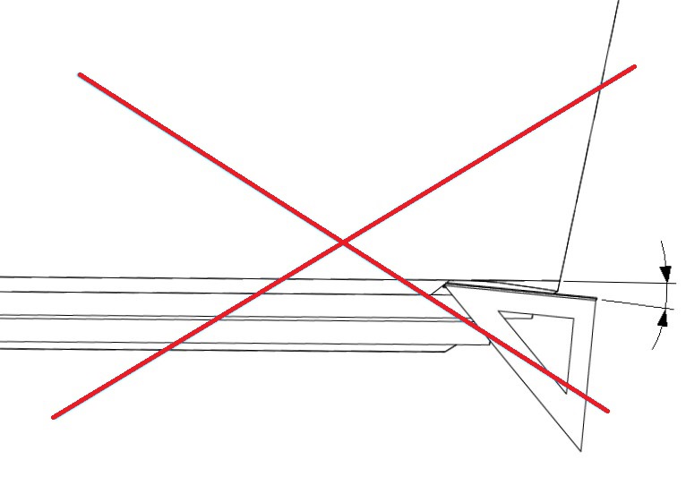
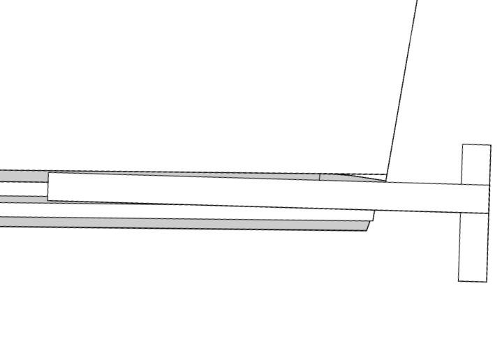
Seakeeper Ride Controllers must be mounted as close to flush with the running surface of the hull as possible, as explained in Section 5. This portion of the installation is to measure the angle at the chosen locations. The Wedge Pack Assembly (Items 4, 5, 6, 7, and 8 in Figure 6) allows for the adjustment of the Controllers to the boat’s transom angle. The figure below illustrates the differences in the angle between the aft end of the running surface and the transom (A) and the resulting effects on Wedge Pack selection (B). The top two images show correct angle adjustments. The bottom two images show incorrect angle adjustments.
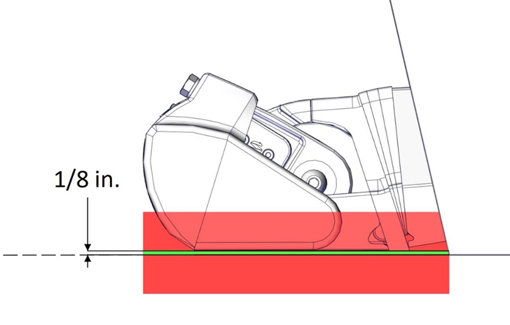
For optimal performance, the Seal Plate must be completely flush with the aft end of the running surface of the boat and up 1/8″. The Seal Plate angle must be between parallel to the hull bottom and upward 2 degrees. DO NOT mount the Controller angled downward at all.
6.1. Measurement Steps
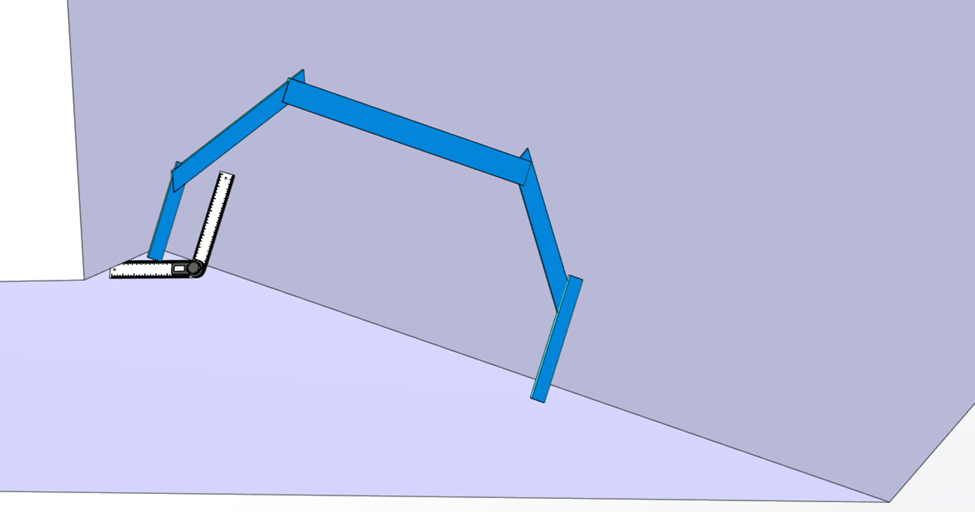
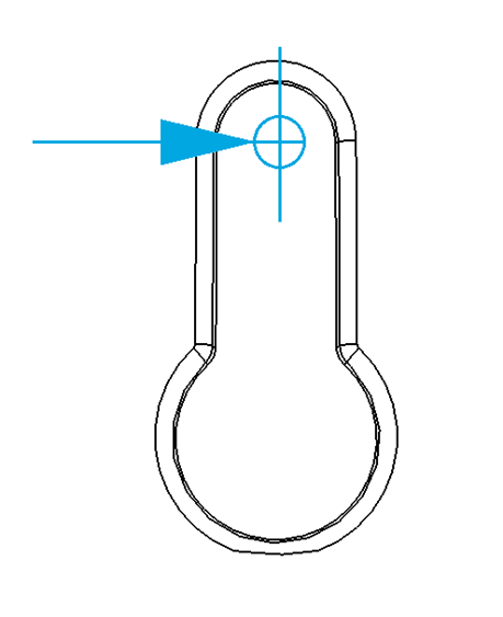
- Using the selected Controller locations from Section 5, measure the angle with a digital protractor from the running surface to the transom, perpendicular to the deadrise. See the figure below for an example of the measurement on the port Controller, outboard location.
- Measure the inboard and outboard ends of the port Controller area and use the larger angle in the following Sections. Round up to the nearest degree.
- Measure inboard and outboard ends of the starboard Controller area and use the larger angle in the following Sections. Round up to the nearest degree. As with every step, repeat measurement process for both port and starboard sides. Note: It is possible to find different angles between port and starboard side of the hull.
- Determine the number of wedges required for each Controller’s Wedge Pack using the transom angle measured in previous sections and Table 2 – Transom Angle and Wedge Plates.
The transom and Wedge angles indicated in the Table 2 are the maximum range of the product. If the boat’s transom angle is outside the range of Table 2, do not add or remove more wedges to accommodate the different angle. The hardware is rated only for the amount of Wedge Plates outlined in the table below to maintain full structural integrity.
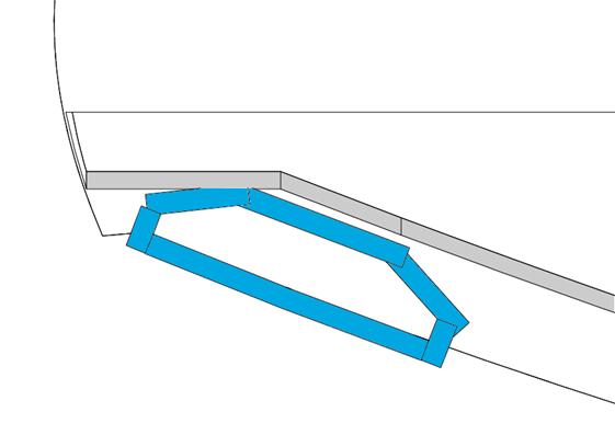
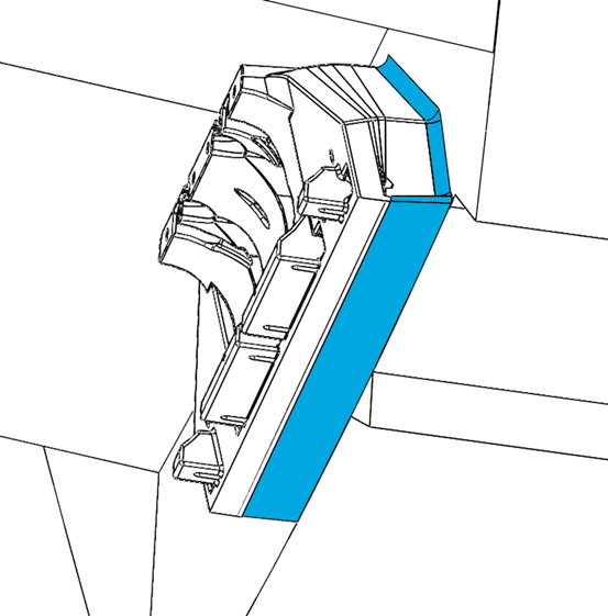
Instead, build out the transom – using materials consistent with the transom structure – to change the angle of the transom in the general footprint of the Transom Plate as shown in blue in Figure 27. When adding material, match the transom’s structural strength. Please consult your Naval Architect or Marine Engineer to verify the structural integrity of the added materials.
Table 2 – Wedge Plates Based on Transom Angle
| Wedge Plates | |||||
| Transom Angle | Measured Angle | 3 Degree | 4 Degree | 5 Degree | Top Bolt Length |
| 68 | 112° | 1 | 50 mm | ||
| 69 | 111° | 1 | 50 mm | ||
| 70 | 110° | 1 | 50 mm | ||
| 71 | 109° | 2 | 60 mm | ||
| 72 | 108° | 1 | 1 | 60 mm | |
| 73 | 107° | 1 | 1 | 60 mm | |
| 74 | 106° | 1 | 1 | 60 mm | |
| 75 | 105° | 2 | 60 mm | ||
| 76 | 104° | 1 | 2 | 60 mm | |
| 77 | 103° | 1 | 1 | 1 | 60 mm |
| 78 | 102° | 1 | 2 | 60 mm | |
| 79 | 101° | 1 | 2 | 60 mm | |
| 80 | 100° | 2 | 1 | 1 | 60 mm |
| 81 | 99° | 2 | 2 | 60 mm | |
| 82 | 98° | 1 | 1 | 2 | 60 mm |
| 83 | 97° | 2 | 2 | 60 mm |
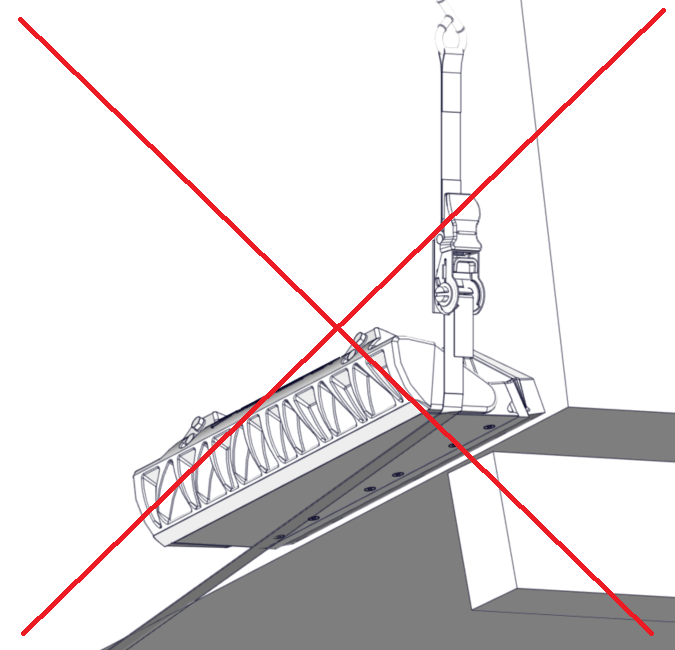
6.2. Hulls with Unique Stern Features
For many planing hulls, the aft portion of the running surface is straight, however, there can be exceptions where there is a curvature, angle, or twist just forward of the transom. This may be referred to as a stern wedge, hook, or rocker. These types of features are generally added the hull to improve handling characteristics or induce a constant trim, adding a bow down moment during normal running conditions.
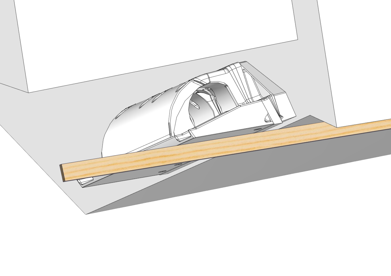
Be sure to use a 3-ft (0.9 m) straight edge along the hull bottom when evaluating the transom angles to obtain a correct assessment of the running surface.
If the Seal Plate were to be installed following the same angle as a stern wedge, it would create a permanent additional upward force in the aft of the boat, and the bow would be pushed down irreversibly. This incorrect assessment for installation is demonstrated below.
Measure the angle of the transom over a greater length of the running surface up to 3-ft (0.9 m) to ensure the proper angle.
7. Assemble Wedge Pack
Assemble Wedge Pack Introduction
This portion of the installation will require the Wedge Pack hardware kit illustrated in Section 4.
7.1. Determine Wedges to Use
Based on Table 2 and the transom angle determined in Section 6, compile the Transom Plate, Actuator Plate, Wedge Pack Hardware kit and appropriate wedges for port and starboard. It is possible that the hull has different angles for each location.
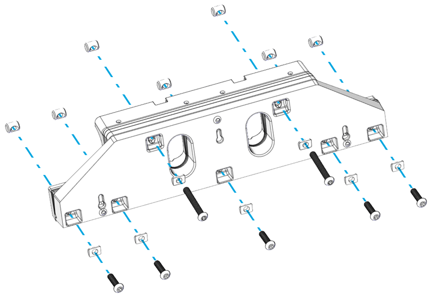
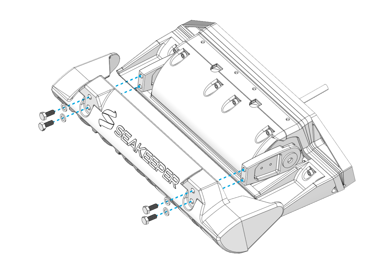
- Stack the proper number of Wedge Plates on top of the Transom Plate using the tabs and grooves on the Wedge Plates shown below to keep them in the correct orientation. There are matching tabs on the Transom Plate to assist with alignment.
- Place the Actuator Plate on top to complete the Wedge Pack Assembly.

7.2. Bolt Parts Together
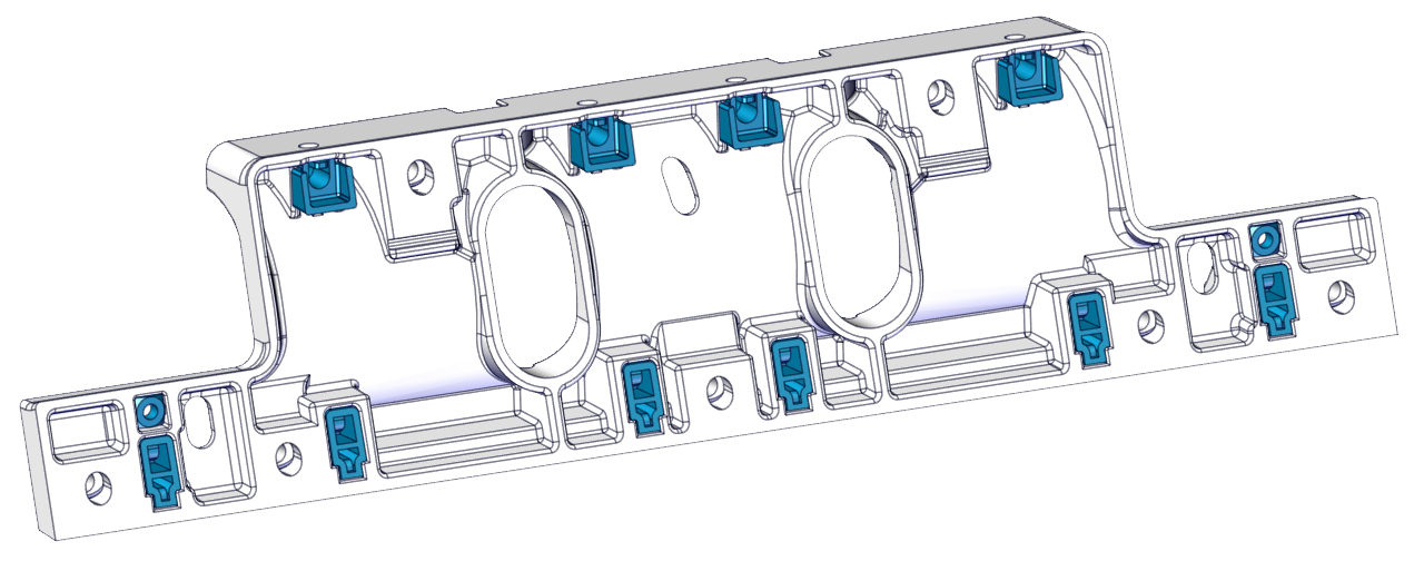
Note: Before bolting parts together, check to make sure that none of the hardware on the back side of the Actuator Plate has fallen out during shipping or handling (highlighted below in blue).
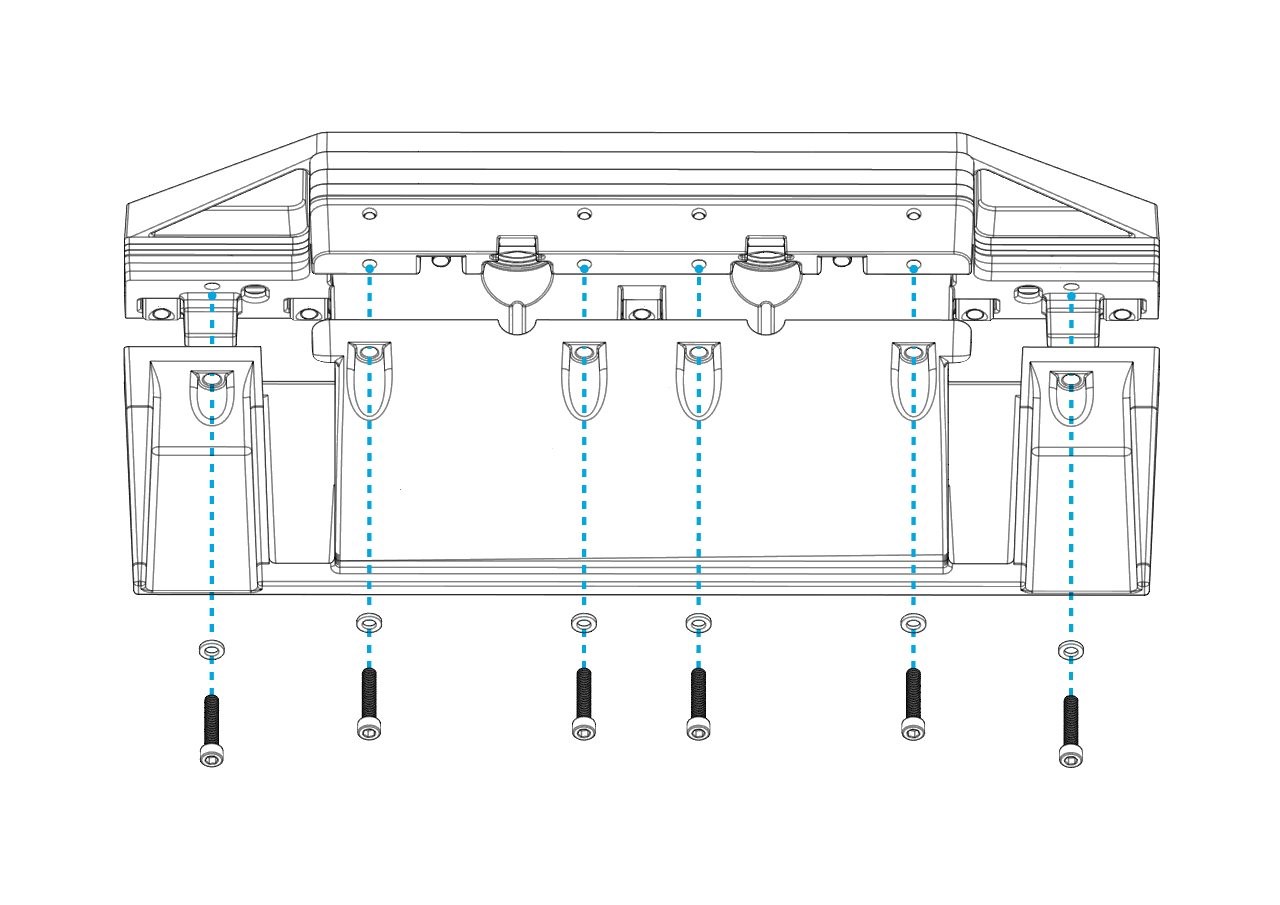
- Place a cylindrical washer on each bolt, with the flat side on the head of the bolt.
- Install the five (5) M8 x 30 mm bolts in the bottom of the Transom Plate, as shown below (The 600 mm Controllers will have seven [7] bolts.)
- The top two (2) M8 bolts must be selected based upon the total Wedge Plates in use. See Table 2 to determine if the 50 mm or 60 mm bolts must be used.
Note: Be sure to use the correct bolt length. Incorrect bolt length may result in insufficient thread engagement or the inability to attach the Seal Plate in later steps.
Note: Insert the bolts from the Transom Plate side NOT the Actuator Plate side. Incorrect bolt direction will likely cause interference when placing the Wedge Pack on the transom.
4. Place cylindrical nuts over the ends of the bolts on the Actuator Plate and torque to 75 in-lbs (8.5 N-m) in an alternating pattern.
8. Prepare Hull
Prepare Hull Introduction
Note: In Section 8 there are different levels of preparation recommended to the installer based upon the age and history of the boat. For original equipment manufacturer (OEM) installations follow all sections except for Section 8.5. For refit installations follow all sections except for Section 8.6.
8.1. Trace Template Outline
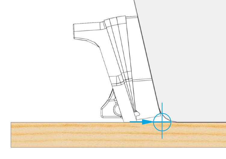
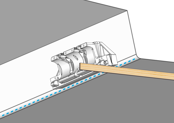
Figure 36 – Wedge Pack Assembly in Line with RRL and Hull Bottom
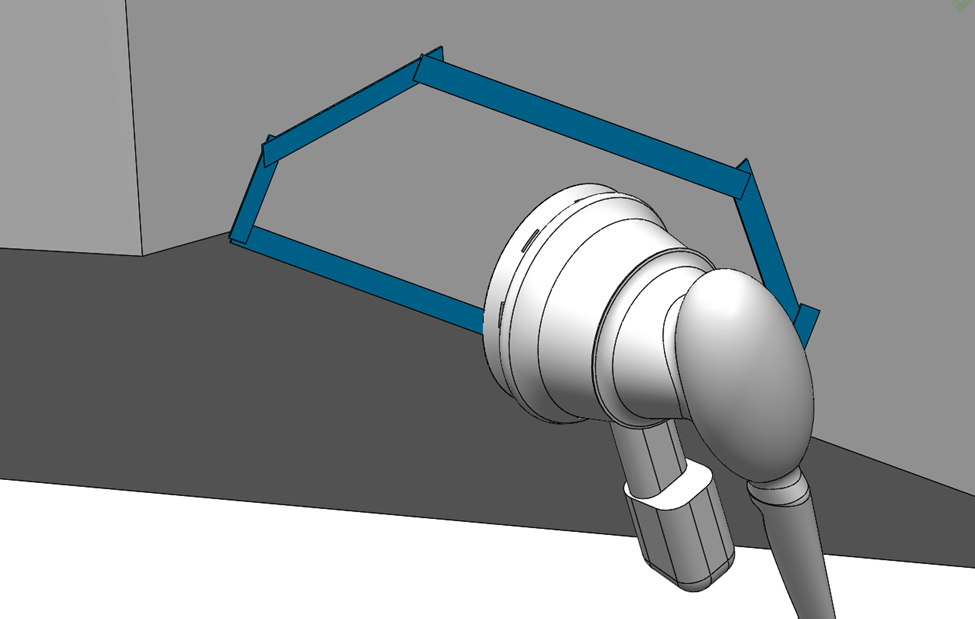
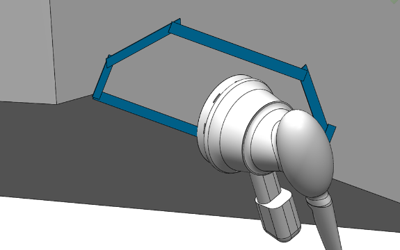
Based on the selection criteria from Section 5 for mounting location, hold the Wedge Pack to the transom in the designated location. Use a straight edge to align the Actuator Plate with the RRL (shown in blue above) and the bottom of the hull. Two people should be available for this section to make holding and tracing easier and more consistent.
Note: Use of the Seakeeper Ride Controller Locator Tool will aid in tracing the area to be ground down to glass and for the correct position of the transom plate positioning screws. This tool will allow for one person to get exact measurements. See the Seakeeper Ride | Controller Locator Tool Manual for further instruction on use.
For optimal Seakeeper Ride performance, the Seal Plate must be between the RRL and 1/8in. up above the RRL. DO NOT mount the Seal Plate below the RRL at all.
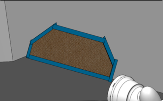
- Using a marker or pencil, trace the outline of the Transom Plate on the transom.
- Trace three (3) mounting hole (keyhole) locations while the Transom Plate is in place.
- Trace out cable entry oval holes.
8.2. Drill Holes
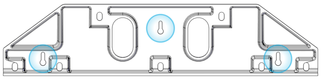
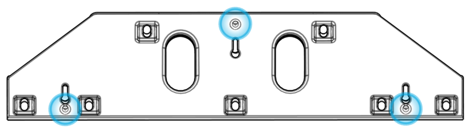
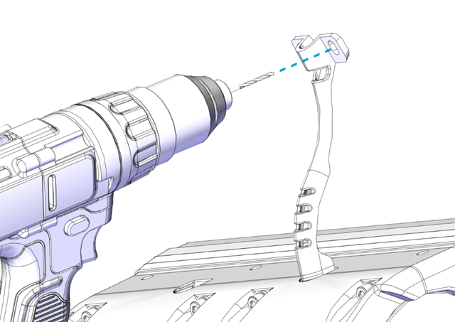
- Drill pilot holes for each of the three (3) positioning screws highlighted in the figure below using a 9/64 in. (3.6 mm) drill bit. The screws will be installed such that they are extending off the transom approximately 3/4 in. (19 mm). Drill the holes at the highest available position of the keyhole slot, as shown below.
- For aluminum hulls it is possible to utilize machine screws to support the transom plate as prepared for in this step. If you wish to use machine screws, drill and tap these holes at this time and locations indicated in this step.
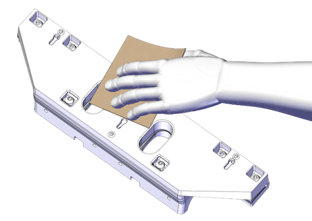
8.3. Wipe Area with Solvent
Using acetone or denatured alcohol and a plain white paper towel, wipe the area down to remove surface contaminants.
8.4. Mask Area with Tape
Mask the area surrounding the Transom Plate with tape to protect the surrounding gelcoat or paint, as shown below. Mask all surfaces below the Ride Reference Line, such as spray strakes.
8.5. Fiberglass Hulls – Abrading Gel Coat
Note: This section is only for new build installations at the boat original equipment manufacturer (OEM) or for boats that meet the following criteria:
- Purchased directly from the OEM.
- Less than 6 months old.
- Known history with virgin gel coat. The boat must never have been painted, repaired, or modified in any way.
If the boat does not meet these requirements, or if there is any uncertainty, follow Section 8.6.
Sand down the gel coat with 60 grit sandpaper to remove the gloss surface. You may use a Dual Action Sander (DA), but you must be extremely careful not to remove excess material. Note: It is important not to change the shape of the transom and to stay within the perimeter of the Transom Plate.
8.6. Fiberglass Hulls – Removing Gel Coat
Note: Follow this section for most refit installations. If the boat does not meet the criteria listed below in Section 8.5, or if there is any uncertainty, continue with this section. Seakeeper requires this level of preparation when using epoxy adhesives based on endurance testing of the adhesives.
If the transom in question has been repaired or modified in any way that would compromise fiberglass bond in the region of the Controller installation, please contact a structural engineer or naval architect to ensure the structure in way of the Controller is suitable for installation. If the structure is deemed acceptable for installation, continue through the following sections.
Grind the area where the Transom Plate is to be mounted, using 60 grit abrasive pad or Dual Action Sander. Remove the outer layers of paint, gel coat, or fairing to reveal the fiberglass beneath.
Note: Be sure to wipe the sanded down area with denatured alcohol to allow for a clean space before adhesive is used.
8.7. Aluminum Hulls
For aluminum hulls, use 80 grit sandpaper, a grinder, wire brush or a Dual Action sander to scuff the entire mounting surface to remove all coatings and oxidation until the Seakeeper Ride Controller area is a rough surface with no impurities for the approved two-part adhesive to adhere to. For aluminum hulls be sure to follow adhesive manufacturers recommendations for surface preparation and application of adhesive.
8.8. Insert Positioning Screws
- Inject sealant in all pilot holes.
- If installing on a fiberglass hull, insert the No. 8 x 1.5 in. positioning screws, leaving the head exposed off the hull by about ¾ in. or 19mm.
- For aluminum hulls, wood screws may be substituted with self-taping screws or machine screws if a drill and tap are utilized.
Note: These positioning screws provide no structural purpose and will not support the weight of the Actuator. These screws are intended to assist with installation only and are not meant to handle any forces created by the Controller.
9. Test Fit
Test Fit Introduction
To ensure proper fit of the equipment, the Seal Plate must be temporarily installed.
Note: While test fitting, verify that the nuts receiving the bolts are lined up correctly. Pay particular attention to the square nuts on the sides or ‘wings’ of the Transom Plate.
9.1. Test Fit the Seal Plate
- Hang the Wedge Pack on the positioning screws. Align the bottom surface of the Wedge Pack Assembly with the deadrise as indicated in Section 5.
- When aligned, tighten the positioning screws to hold the Wedge Pack in place.
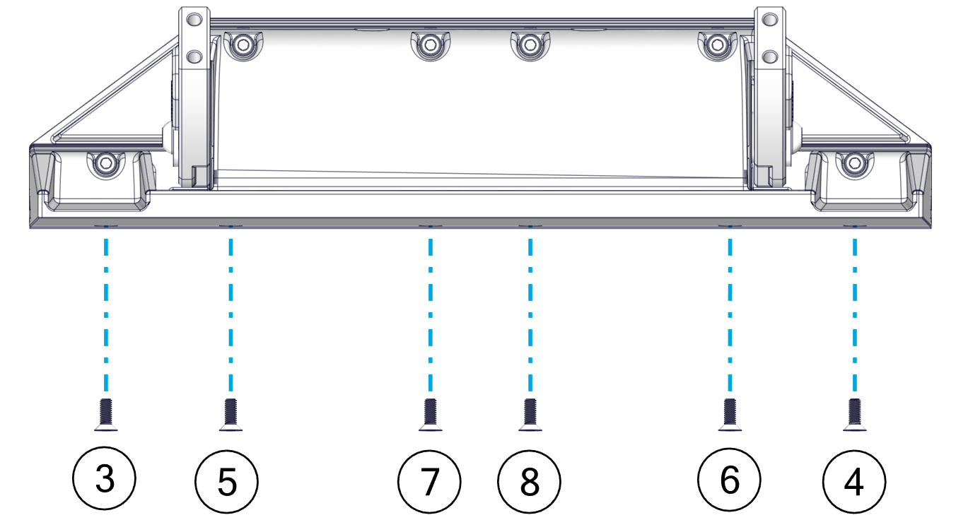
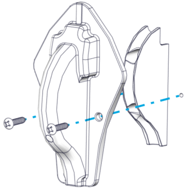
- Add the Seal Plate to the assembly to check its position as indicated in Section 5. Insert the six (6) M6-1.0 x 30 mm bolts and washers to hold the Seal Plate, as shown below after applying Vibra-Tite thread locker to bolts. (600 mm Controllers will have eight [8] bolts and washers.) Note: Apply thread locker, but do not apply the final torque during this step.

- Using a straight edge, verify that the Seal Plate is between flush and up 1/8″ above the hull bottom in the desired location as shown above. Due to different hull shapes and features, the Seal Plate may not be flush with the hull bottom across its full span. However, make sure no part of the Controller is below the RRL. For more information, refer to Section 5.
- If the Seal Plate is not flush in the location needed, repeat Section 7, modifying the number of Wedge Plates until the correct angle has been achieved. Note: When removing and re-inserting bolts, be cautious of debris on the hardware that can cause it to bind, including old thread locker, dirt, etc.
- Once fit is satisfactory, mark the alignment with a writing utensil on inboard and outboard sides of the Transom Plate to make the final mounting easier.
- Remove the Seal Plate from the Wedge Pack using the six (6) M6-1.0 x 30 mm bolts and washers (eight [8] on a 600 mm Controller).
10. Drill for Cable Entry
Drill for Cable Entry Introduction
The Seakeeper Ride system can be installed on a variety of boats with different space and size constraints for the Actuator Cable entry. Based on the selection of cable entry determined in Section 5.7, follow either Section 10.1 for Concealed Cable Entry or Section 10.2 for Exposed Cable Entry.
10.1. Concealed Cable Entry
The cable routing can be concealed if the hull structure allows for it. Follow this procedure for mounting the supplied protective conduit for the Actuator cable.
- Check for available space on the interior of the hull and clean access to the transom prior to starting the Concealed Cable Entry procedure. Verify there is no structure or cable in the way of either inboard or outboard oval hole location of the Wedge Pack Assembly.
- Assemble the Drill Guide by placing the Drill Guide Tube inside of the follower with the rounded part of the tube on the outer diameter of the follower, as shown below. The tube should telescope in and out of the follower freely.

- Leave the Wedge Pack in place as fitted during Section 9.
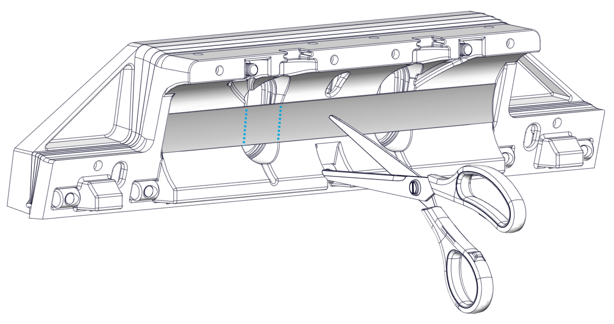
- If the Friction Gasket is covering the portion where the Cable Gland tube will be, cut away at the opening using a razor blade or scissors.
- Place the Drill Guide Assembly in one of the oval cable ports in the Wedge Pack Assembly as shown below.
- The inboard or outboard oval cable port in the Wedge Pack Assembly can be used depending on available inboard space.

- Press the face of the Drill Guide flush with the transom of the boat. Use this to create a 1/4 in. (6.4 mm) pilot hole in the transom.
- Remove the Drill Guide.
- Loosen the positioning screws that are holding the Wedge Pack in place, then remove the Wedge Pack Assembly.
- Drill out the pilot hole to match the diameter of the Cable Gland with a 3/4 in. (19 mm) drill bit.
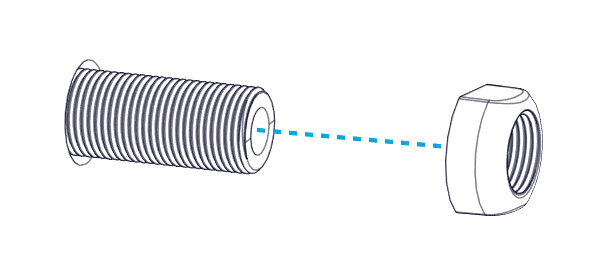
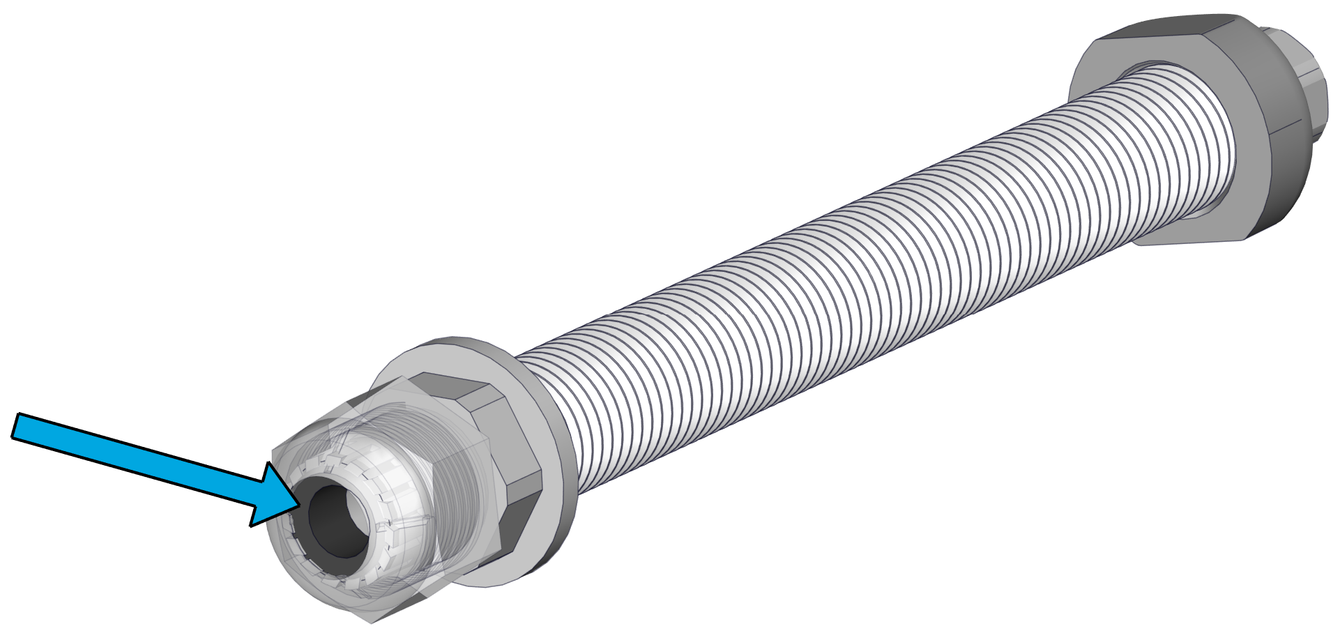
- Apply a liberal amount of sealant on the outer diameter of the Cable Gland tube (See figure below, Left). Install the Cable Gland tube from the inboard side of the transom.
- Apply more sealant where the tube meets the outboard side of the transom (See figure below, Right).
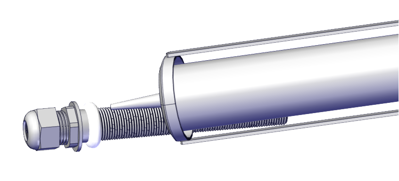
- Install the Nut on the outboard side of the transom. Tighten until the Nut contacts the transom. Do not overtighten.
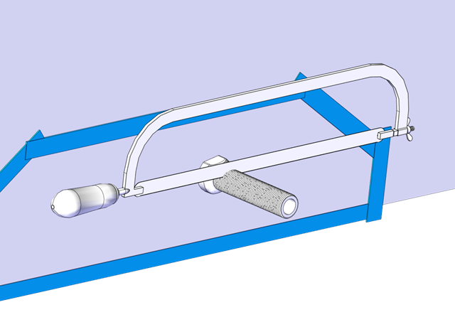
- Cut off the excess threads on the outboard side off using a hacksaw or oscillating tool.
10.2. Exposed Cable Entry
In the instance in which the Actuator cable will be exposed, follow this procedure for mounting the supplied protective conduit for the Actuator cable.
Note: The shape of the Outer Cable Guide is designed to cover most holes left by previous trim tabs when using the same cable hole.
- Check for structural clearances and rigging inside the hull before proceeding with drilling holes for the cable route in the transom.
- Determine the ideal location where the cable will penetrate the hull based on Section 5.7
- Using 3/4 in. (19 mm) drill-bit or hole saw, drill a hole through the transom.
- Apply a liberal amount of sealant on the outer diameter of the gland. Install the Cable Gland Tube from the inside (Figure 52 – Sealant Application to Cable Gland).
- Note: Though not the preferred method, if circumstances dictate, the Cable Gland Tube CAN be inserted from the outside when doing exposed cable entry. However, the Nut will need to be installed from the inside, and the Cable Guide and Cover will not be able to be installed.
- Install the Nut on the outboard side of the transom. Tighten until the Nut contacts the transom. Do not overtighten (Figure 52 – Outboard Cable Gland Nut Installation).
- Cut off the excess threads on the outboard side using a hacksaw or oscillating tool (Figure 54 – Cable Gland Trimming).
- Hold the Inner Cable guide up to the Cable Gland in the desired mounting location. Mark the locations of the two (2) mounting screws and drill 3/32 in. (2.4 mm) pilot holes in these locations.
- Inject sealant in both pilot holes. Use a screwdriver to install the two (2) No. 8 x 1-1/2 in. screws to mount the Inner Cable Guide.

11. Mount Wedge Pack
Mount Wedge Pack Introduction
Care must be taken to ensure clean working conditions. Wearing clean gloves is highly recommended to keep caustic substances off skin and prevent oil and grease from getting on adhesive surfaces.
For concealed cable entry, take note of the Actuator cable routing side. Knowing the routing side will be required when configuring the system.
11.1. Prepare Parts and Hull
- Wipe the area to be bonded with acetone or denatured alcohol and plain white paper towels.
- Replace the tape around the border of the abraded portion of the transom where the Transom Plate will be mounted. Mask around the mounting location as well as the bottom of the boat. The tape will help keep the surrounding gelcoat clean of adhesive. The inside of the Cable Gland should be covered to avoid adhesive from entering the gland, particularly when installing with a Concealed Cable Entry as indicated in Section 10.1.

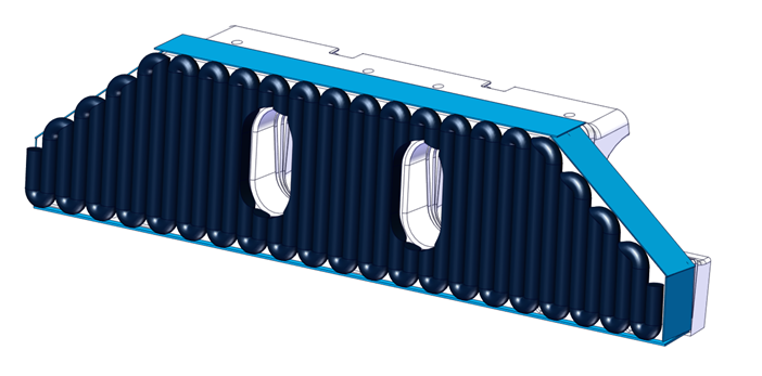
- Tape the top and side edges of the Wedge Pack Assembly. Note: The drain holes on the Wedge Pack Assembly, circled in the figure below must be covered with tape to avoid adhesive clogging them.
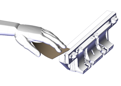
- Wipe the Wedge Pack down with acetone or denatured alcohol using plain white paper towels to remove oil/surface contaminants.
11.2. Sand Adhered Surface
- Using 60 grit sandpaper, scuff the entire back and bottom of the Transom Plate by hand. You may use a Dual Action Sander (DA), but you must be extremely careful not to remove excess material. DO NOT use a grinder or heavy abrasive for this process. The mounting surface of the Transom Plate should have a matte gray finish when properly prepared with sandpaper. Note: Be careful not to sand down the standoff bumps on the plate circled in blue below.
11.3. Clean Adhered Surfaces
- Wipe the Wedge Pack down with acetone or denatured alcohol and plain white paper towels a second time to remove oil and/or surface contaminants after sanding.
- Clean the transom mounting location with acetone or denatured alcohol and plain white paper towels a second time to remove oil and/or surface contaminants after sanding.
11.4. Mount Wedge Pack
Note: For concealed cable entry, the Cable Gland Tube must be inserted before mounting the Wedge Pack.
- Apply approved two-part adhesive to both the Transom Plate and transom. Use at least the amount of adhesive listed in the table below to ensure both surfaces are covered completely by adhesive. There must be enough adhesive between the Transom Plate and the transom for a strong bond with no voids. The Transom Plate has three (3) stand offs to allow for adequate adhesive thickness once mounted. Note: Work from this point on should be deliberate, keeping in mind the working time of the adhesive being applied. Warmer temperatures reduce working time.
Please verify the approved two-part adhesive selected from the list is compatible with your hull material. If in doubt, contact the approved two-part adhesive manufacturer for best practice instructions with your given hull material. Some materials may require a primer for best adhesion. See here 3. Tools Needed – Seakeeper Manuals
Approved two-part adhesives come in multiple mixing ratios – 1:1, 2:1, or 10:1. Use the correct dispense gun and mixing nozzles for the adhesive type. Failure to do so will result in poor adhesion and will void the systems warranty.
Table 3 – Adhesive Quantity
Quantity:
| Controller Size | Minimum Adhesive Quantity (per boat) | Minimum Adhesive Quantity (per Controller) |
| 450 mm | 900 ml | 450 ml |
| 525 mm | 1050 ml | 525 ml |
| 600 mm | 1200 ml | 600 ml |
- Install the Wedge Pack Assembly by sliding the keyholes over the positioning screws. Excess adhesive should appear around the entire perimeter of the Wedge Pack Assembly as the Wedge Pack is pressed into place.
11.5. Confirm Location
- Add the Seal Plate to the assembly to check its position as indicated in Section 9. Insert the six (6) M6-1.0 x 30 mm bolts and washers to hold the Seal Plate, as shown below. (600 mm Controllers will have eight [8] bolts and washers.) Note: Apply threadlocker, but do not apply the final torque during this step.
- Using a straight edge, verify the Wedge Pack is flush with the hull bottom in the desired location as determined in Section 5. Be sure location requirements previously called out are met. Due to different hull shapes and features, the Seal Plate may not be flush with the hull bottom across its full span.
- Once the position is confirmed, remove the Seal Plate, and tighten the positioning screws with a Phillips head screwdriver. The screws must be tight enough to press out excess adhesive and keep the assembly from sagging, but do not overtighten or the transom plate may crack.
Note: In the uncommon case that the measured transom angles for the inboard and outboard sides of a Controller location (found in Section 6.1) are greater than 2 degrees apart, tighten beginning on the side with the larger transom angle pulling it tight to the transom. On the side with the smaller transom angle, gently advance the screws but do not tighten it all the way to the transom. If the screws on the side of the smaller transom angle are overtightened, the Wedge Pack will warp and cause issues.
11.6. Fair in Excess Glue
- Using a squeegee, putty knife, or tongue depressor, fill in the gap between the running surface of the hull and the Actuator Plate with excess adhesive, as shown below. Apply extra adhesive as needed. Note: The smooth transition from the hull bottom to the Seal Plate is critical for achieving the best performance out of the system.
- Using a squeegee, putty knife, or tongue depressor, clean away excess adhesive.
ATTENTION: For concealed cable entry, clean out all of the adhesive from around the Cable Gland. You must make sure the Cable Gland will be accessible after the adhesive cures.
- Make a smooth transition with adhesive on the upper edges of the Transom Plate to the transom. Apply extra adhesive as needed.
- Remove the masking tape from the Wedge Pack Assembly and transom. If needed, clean any excess adhesive using acetone or denatured alcohol and plain white paper towels.
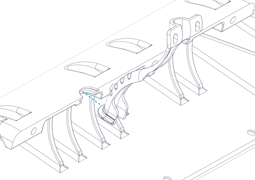
- After fairing, check that the drain hole has remained clear. See Figure 57.
- Allow adhesive to cure before proceeding. Some adhesives have ‘handling times’ where the product feels firm but is not ready for loading. Some adhesives also have required times before submersion. Please follow the adhesive manufacturer’s instructions.
- For aluminum hulls, upon completion of the installation use a paint or similar coatings to protect the edges of aluminum from corrosion seeping between the approved two-part adhesive and aluminum.
12. Actuator and Blade Installation
Actuator and Blade Installation Introduction
The final stages of installation are differentiated by the cable entry into the hull. If you are following a concealed cable entry, follow the procedure detailed in Section 12.1. For exposed cable entry, follow procedure in Section 12.2.
Note: Do not bend the Actuator Cable at a radius smaller than 50 mm (1.97 in.) to avoid damaging the cable. Do not lift the Actuator by the cable when removing from the box or anytime carrying.
12.1. Concealed Cable Entry
ATTENTION: The following procedure must be followed with careful attention to the sequence of bolts, correct thread locker and correct torque applied to the bolts. Not following the procedure correctly can result in poor Ride performance.
ATTENTION: DO NOT pickup the Actuator by the cable or allow it to hang by the cable. Doing so could compromise to the watertight seal of the Actuator and cause system malfunction.
Note: The Cable Gland must have the black rubber grommet in place to properly seal. Ensure the grommet is present and remains in place while inserting the Actuator cables. The outside of the cable must be clean of debris, dust, adhesives, etc. to properly seal. Do not allow acetone to come in contact with the Controller Cable Gland Sealing Nut.
1. Align the Actuator so the cable passes through the hole in the Wedge Pack Assembly and the Cable Gland. Feed the Actuator Cable through the Cable Gland and remove as much slack from the outboard side as possible.
2. Set the Seal Plate over the Actuator, secure it in place with two (2) M6-1.0 x 30mm Socket Head Cap Screws in wing positions. Apply Vibra-Tite 132 thread locker to the screws. Torque screws to 60 in-lbs (6.8 N-m). (Note: The Seakeeper Ride 600 system will have four (4) screws).
Apply Torque two (2) times to ensure fasteners are seated.

3. Secure the Seal Plate bottom with six (6) M6-1.0 x 16 mm Flat Head Socket Cap Screws from the bottom edge of the Seal Plate and apply Vibra-Tite 132 thread locker to the screws. Torque screws to 60 in-lbs (6.8 N-m). (Note: The Seakeeper Ride 600 system will have eight (8) screws).
Apply Torque two (2) times to ensure fasteners are seated.
4. Secure the Seal Plate top with the four (4) M6-1.0 x 30mm Socket Head Cap Screws from the top face of the Seal Plate, and apply Vibra-Tite 132 thread locker to the screws. Torque screws to 60 in-lbs (6.8 N-m).
Apply Torque two (2) times to ensure fasteners are seated.
5. Tighten the Cable Gland on the inboard side of the transom. The Cable Gland should be snug to prevent leaking, but do not overtighten. Gently pull on the cable to ensure there is no movement and prove it is sealing securely.
6. Install the Blade to the Actuator Arms using the four (4) M8-1.25 x 20 mm screws and their washers. Apply Vibra-Tite 132 thread locker to the screws. Torque these four (4) bolts to 80 in-lbs (9.0 N-m) in an ‘X’ pattern.
- Once installed, push the Blade all the way down and verify that the Blade is not contacting the Seal Plate. There should be a small, even gap between the Blade and the Seal Plate.
- Before torquing, the Blade can be slid up and down slightly to bring it closer and farther away from the Seal Plate, respectively. If the Blade is rubbing and creating friction against the Seal Plate, or if the gap appears too large, adjust the Blade accordingly. Contact Seakeeper if there are still concerns with Blade gap tolerance after following these instructions.
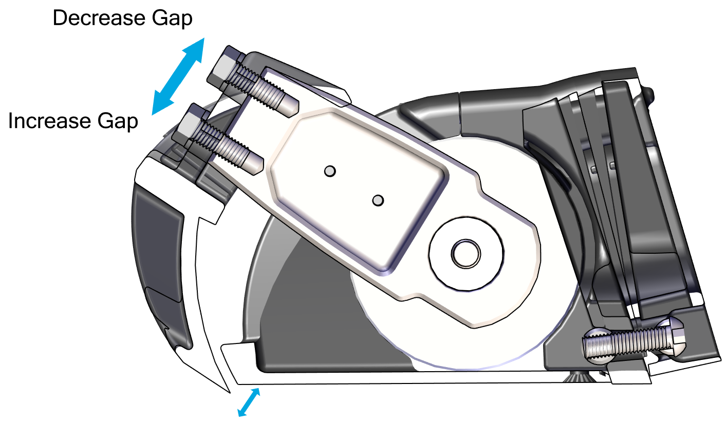
Note: Maintaining this gap between the Blade and Seal Plate is critical to maintaining factory tested failure mode performance. If the gap between the Blade and Seal Plate is too large, system performance will fall off. If the Blade contacts the Seal Plate, the friction will slow down the system’s response time, also reducing performance.
To maintain the factory fitment:
- Do not apply anti-fouling coating to the surfaces between the Blade and Seal Plate in order to avoid changing the fit of those parts.
- Always keep the surfaces between the Blade and Seal Plate clean and free from debris, including naturally occurring debris (such as marine debris) and other debris (such as paint or coating.
- When repairing or replacing any components on the Controller, confirm that the Blade rotates by hand. Resistance will be felt from the Actuator, but there must be no additional grinding or friction inhibiting movement.
- Allow the adhesive to cure fully before sea trialing the boat.
Each adhesive has a full cure time or close to full cure, which must be met before any load is applied. After the installation is complete, before sea trialing the boat, wait at least the full cure time advertised by the adhesive manufacturer in the temperature during the install, or 24 hours, whichever is greater. Colder temperatures increase fixture time and cure time. (In very cold climates, the adhesive may need to cure for multiple days before sea trialing.) Refer to technical data sheets (TDS) and manufacturer recommendations for the particular adhesive being used.
12.2. Exposed Cable Entry
 ATTENTION: The following procedure must be followed with careful attention to the sequence of bolts, correct thread locker and correct torque applied to the bolts. Not following the procedure correctly can result in poor Ride performance.
- Install the Cable Guide Support in the groove in the Seal Plate.
2. Install the Actuator in the Seal Plate. Route the Actuator Cable through the Cable Guide Support.
3. Set the Seal Plate back overthe Actuator, secure it in place with two (2) M6-1.0 x 30mm Socket Head Cap Screws in wing positions. Apply Vibra-Tite 132 thread locker to the screws. Torque screws to 60 in-lbs (6.8 N-m). (Note: The Seakeeper Ride 600 system will have four (4) screws).
Apply Torque two (2) times to ensure fasteners are seated.
4. Secure the Seal Plate bottom with six (6) M6-1.0 x 16 mm Flat Head Socket Cap Screws from the bottom edge of the Seal Plate and apply Vibra-Tite 132 thread locker to the screws. Torque screws to 60 in-lbs (6.8 N-m). (Note: The Seakeeper Ride 600 system will have eight (8) screws). Torque of 60 in-lbs (6.8 N-m) is 20% greater than previously specified.
Apply Torque two (2) times to ensure fasteners are seated.
5. Secure the Seal Plate top with the four (4) M6-1.0 x 30mm Socket Head Cap Screws from the top face of the Seal Plate and, apply Vibra-Tite 132 thread locker to the screws. Torque screws to 60 in-lbs (6.8 N-m).
Apply Torque two (2) times to ensure fasteners are seated.
6. Mount the Cable Guide Support in line with the natural path of the Actuator Cable to the transom. Pre-drill two (2) mounting screw pilot holes using a 3/32 in. (2.4 mm) bit. Inject sealant into the holes. Insert two (2) No. 8 x 0.75 in. screws and tighten with a Phillips head screwdriver.
- Route the Actuator cable over the Inner Cable Guide. Feed as much cable as possible through the Cable Gland Tube.
- Tighten the Cable Gland around the Actuator Cable on the inboard side of the transom (See Figure 67 – Cable Gland Installation Inboard of Transom). The Cable Gland should be snug to prevent leaking, but do not overtighten. Gently pull on the cable to ensure there is no movement and prove it is sealing securely. Note: The Cable Gland must have the rubber grommet in place to properly seal. The outside of the cable must be clean of debris, dust, adhesives, etc. to properly seal. Do not allow acetone to come in contact with the Controller Cable Gland Sealing Nut.
- Place the Outer Cable Guide over the Inner Cable Guide. Mark the location of the two (2) mounting screw holes. Drill 1/8 in. (3.2 mm) pilot holes in these two (2) locations.
- Note: The shape of the Outer Cable Guide is designed to cover most holes left by previous trim tabs when using the same cable hole.
- Inject sealant into the pilot holes for the mounting screws for the Outer Cable Guide. Using a Phillips head screwdriver, install the two (2) No. 10 x 1 in. mounting screws into the hull and hand-tighten.
- Install the Blade to the Actuator Arms using the four (4) M8-1.25×20 mm screws and their washers. Apply Vibra-Tite 132 thread locker to the screws. Torque these four (4) bolts to 80 in-lbs (9.0 N-m) in an ‘X’ pattern (Figure 68 – Blade Installation).
- Once installed, push the Blade all the way down and verify that the Blade is not contacting the Seal Plate. There should be a small, even gap between the Blade and the Seal Plate.
- Before torquing, the Blade can be slid up and down slightly to bring it closer and farther away from the Seal Plate, respectively. If the Blade is rubbing and creating friction against the Seal Plate, or if the gap appears too large, adjust the Blade accordingly. Contact Seakeeper if there are still concerns with Blade gap tolerance after following these instructions. (Figure 69 – Blade Gap Adjustment)
Note: Maintaining this gap between the Blade and Seal Plate is critical to maintaining factory tested failure mode performance. If the gap between the Blade and Seal Plate is too large, system performance will fall off. If the Blade contacts the Seal Plate, the friction will slow down the system’s response time, also reducing performance.
To maintain the factory fitment:
- Do not apply anti-fouling coating to the surfaces between the Blade and Seal Plate in order to avoid changing the fit of those parts.
- Always keep the surfaces between the Blade and Seal Plate clean and free from debris, including naturally occurring debris (such as marine debris) and other debris (such as paint or coating.
- When repairing or replacing any components on the Controller, confirm that the Blade rotates by hand. Resistance will be felt from the Actuator, but there must be no additional grinding or friction inhibiting movement.
- Allow the adhesive to cure fully before sea trialing the boat.
Each adhesive has a full cure time or close to full cure, which must be met before any load is applied. After the installation is complete, before sea trialing the boat, wait at least the full cure time advertised by the adhesive manufacturer in the temperature during the install, or 24 hours, whichever is greater. Colder temperatures increase fixture time and cure time. (In very cold climates, the adhesive may need to cure for multiple days before sea trialing.) Refer to technical data sheets (TDS) and manufacturer recommendations for the particular adhesive being used.