Mechanical Installation Manual (450, 525, 600)
8. Prepare Hull
Prepare Hull Introduction
Note: In Section 8 there are different levels of preparation recommended to the installer based upon the age and history of the boat. For original equipment manufacturer (OEM) installations follow all sections except for Section 8.5. For refit installations follow all sections except for Section 8.6.
8.1. Trace Template Outline
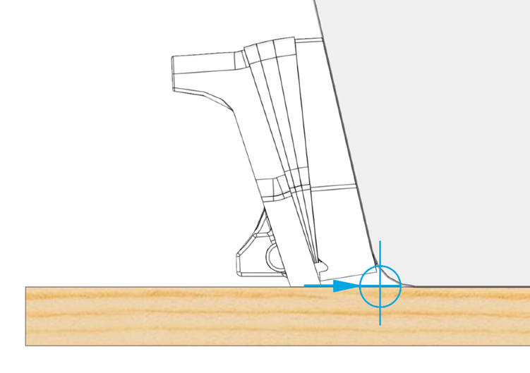
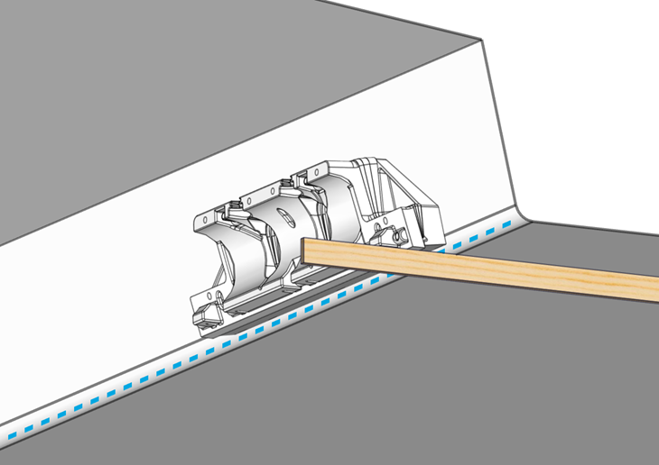
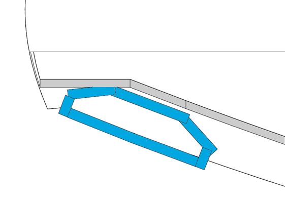
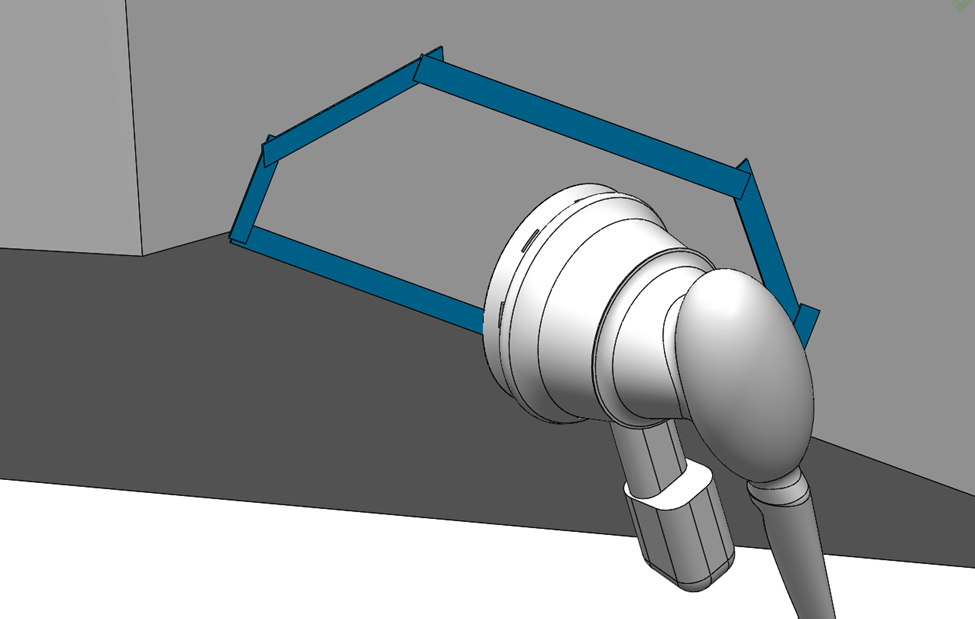
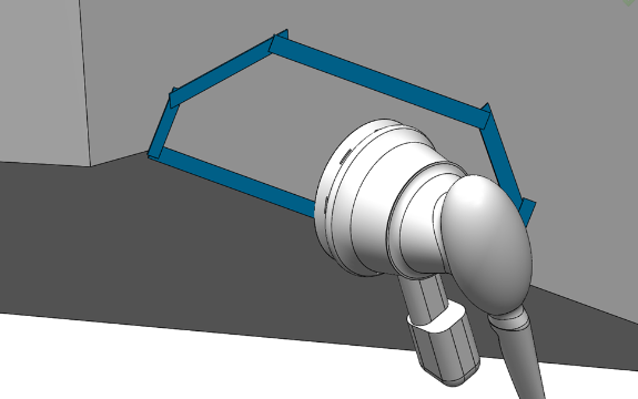
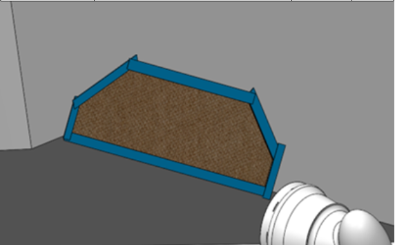
Figure 36 – Wedge Pack Assembly in Line with RRL and Hull Bottom
Based on the selection criteria from Section 5 for mounting location, hold the Wedge Pack to the transom in the designated location. Use a straight edge to align the Actuator Plate with the RRL (shown in blue above) and the bottom of the hull. Two people should be available for this section to make holding and tracing easier and more consistent.
Note: Use of the Seakeeper Ride Controller Locator Tool will aid in tracing the area to be ground down to glass and for the correct position of the transom plate positioning screws. This tool will allow for one person to get exact measurements. See the Seakeeper Ride | Controller Locator Tool Manual for further instruction on use.
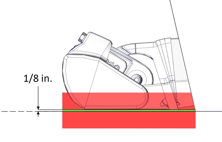
For optimal Seakeeper Ride performance, the Seal Plate must be between the RRL and 1/8in. up above the RRL. DO NOT mount the Seal Plate below the RRL at all.
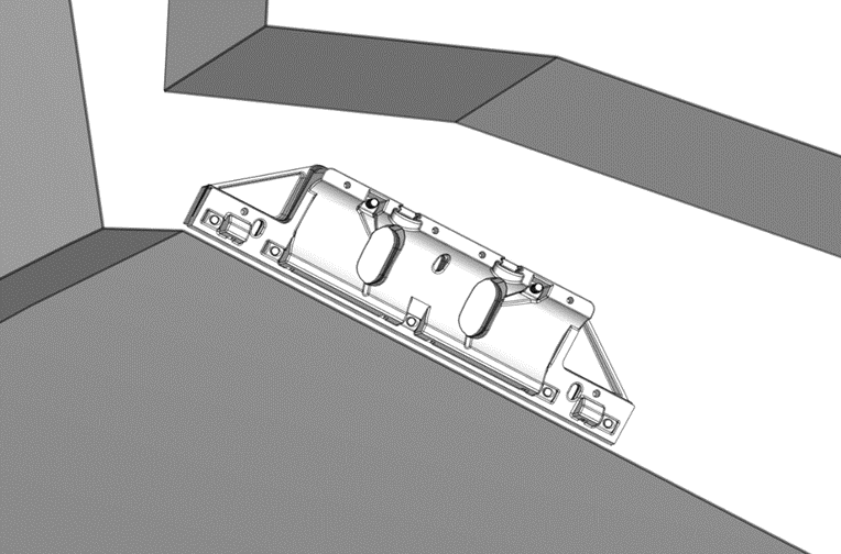
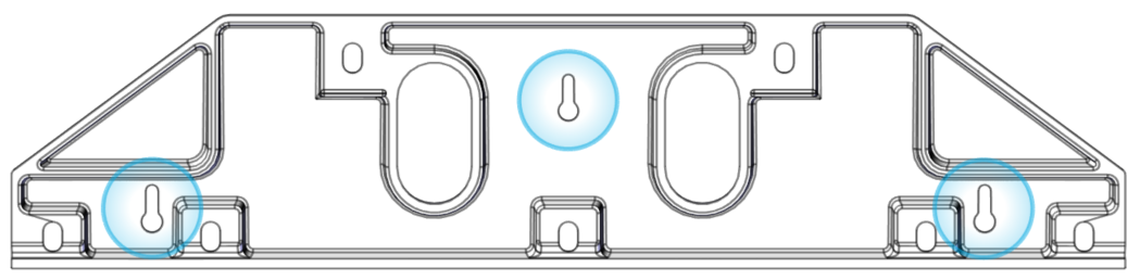
- Using a marker or pencil, trace the outline of the Transom Plate on the transom.
- Trace three (3) mounting hole (keyhole) locations while the Transom Plate is in place.
- Trace out cable entry oval holes.
8.2. Drill Holes
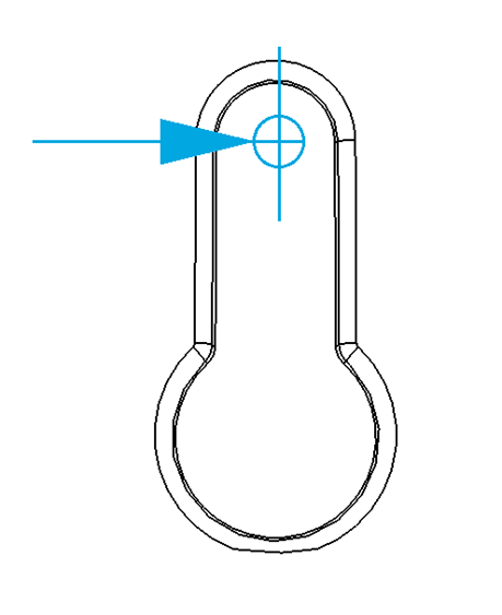
- Drill pilot holes for each of the three (3) positioning screws highlighted in the figure below using a 9/64 in. (3.6 mm) drill bit. The screws will be installed such that they are extending off the transom approximately 3/4 in. (19 mm). Drill the holes at the highest available position of the keyhole slot, as shown below.
- For aluminum hulls it is possible to utilize machine screws to support the transom plate as prepared for in this step. If you wish to use machine screws, drill and tap these holes at this time and locations indicated in this step.
8.3. Wipe Area with Solvent
Using acetone or denatured alcohol and a plain white paper towel, wipe the area down to remove surface contaminants.
8.4. Mask Area with Tape
Mask the area surrounding the Transom Plate with tape to protect the surrounding gelcoat or paint, as shown below. Mask all surfaces below the Ride Reference Line, such as spray strakes.
8.5. Fiberglass Hulls – Abrading Gel Coat
Note: This section is only for new build installations at the boat original equipment manufacturer (OEM) or for boats that meet the following criteria:
- Purchased directly from the OEM.
- Less than 6 months old.
- Known history with virgin gel coat. The boat must never have been painted, repaired, or modified in any way.
If the boat does not meet these requirements, or if there is any uncertainty, follow Section 8.6.
Sand down the gel coat with 60 grit sandpaper to remove the gloss surface. You may use a Dual Action Sander (DA), but you must be extremely careful not to remove excess material. Note: It is important not to change the shape of the transom and to stay within the perimeter of the Transom Plate.
8.6. Fiberglass Hulls – Removing Gel Coat
Note: Follow this section for most refit installations. If the boat does not meet the criteria listed below in Section 8.5, or if there is any uncertainty, continue with this section. Seakeeper requires this level of preparation when using epoxy adhesives based on endurance testing of the adhesives.
If the transom in question has been repaired or modified in any way that would compromise fiberglass bond in the region of the Controller installation, please contact a structural engineer or naval architect to ensure the structure in way of the Controller is suitable for installation. If the structure is deemed acceptable for installation, continue through the following sections.
Grind the area where the Transom Plate is to be mounted, using 60 grit abrasive pad or Dual Action Sander. Remove the outer layers of paint, gel coat, or fairing to reveal the fiberglass beneath.
Note: Be sure to wipe the sanded down area with denatured alcohol to allow for a clean space before adhesive is used.
8.7. Aluminum Hulls
For aluminum hulls, use 80 grit sandpaper, a grinder, wire brush or a Dual Action sander to scuff the entire mounting surface to remove all coatings and oxidation until the Seakeeper Ride Controller area is a rough surface with no impurities for the approved two-part adhesive to adhere to. For aluminum hulls be sure to follow adhesive manufacturers recommendations for surface preparation and application of adhesive.
8.8. Insert Positioning Screws
- Inject sealant in all pilot holes.
- If installing on a fiberglass hull, insert the No. 8 x 1.5 in. positioning screws, leaving the head exposed off the hull by about ¾ in. or 19mm.
- For aluminum hulls, wood screws may be substituted with self-taping screws or machine screws if a drill and tap are utilized.
Note: These positioning screws provide no structural purpose and will not support the weight of the Actuator. These screws are intended to assist with installation only and are not meant to handle any forces created by the Controller.