Mechanical Installation Manual (450, 525, 600)
5.3. Beam-Wise Location
There are several hull features that should be considered when determining the location of the Controllers in a beam-wise orientation. As a general rule, the Controllers must be mounted as far outboard as possible, up to the chines (if the hull has chines).

ATTENTION: Mounting the Controllers towards the centerline of the boat reduces the leverage the system has on the boat and severely reduces roll performance.

Chines
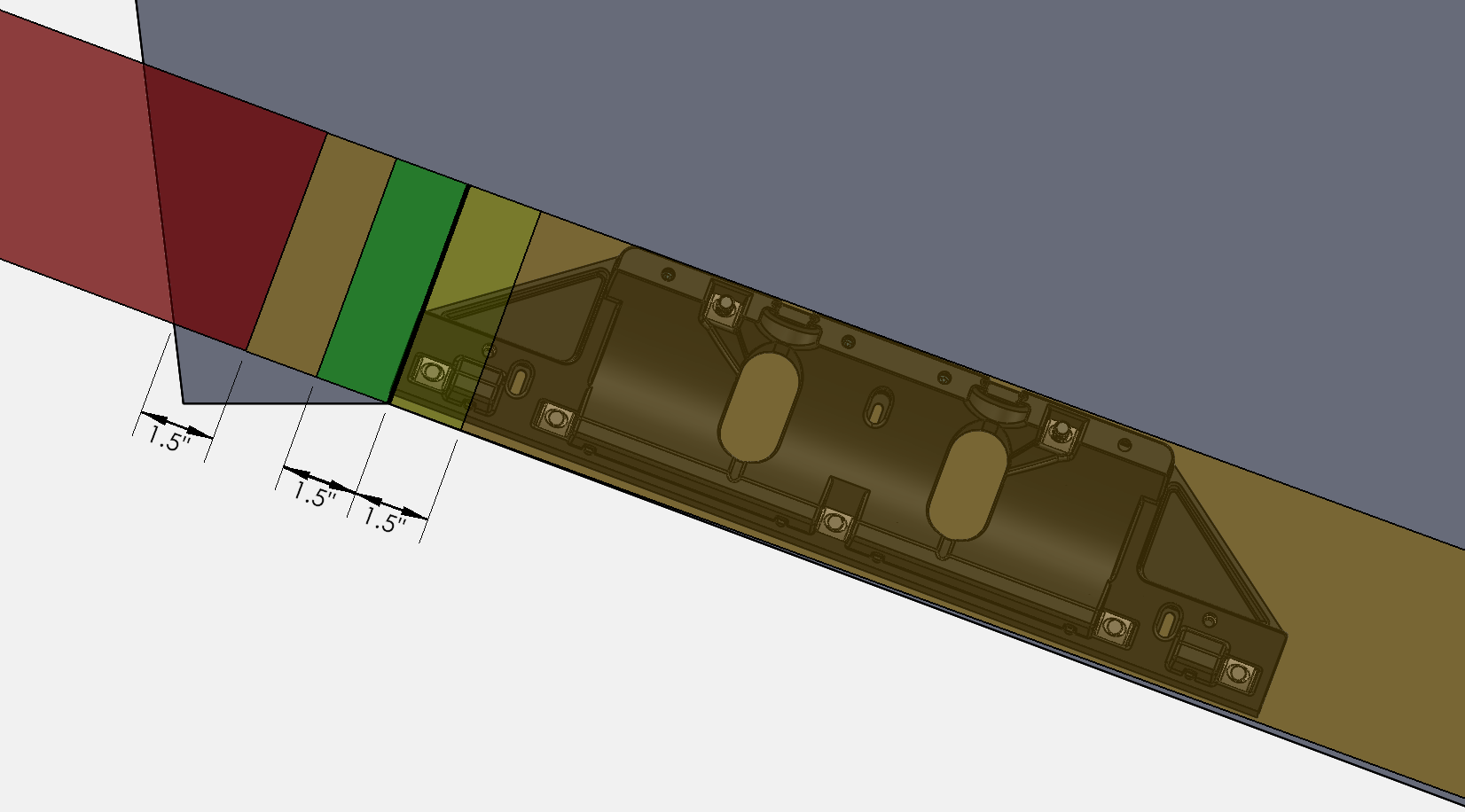
Based on the considerations of engine spacing and transom appendages, some installations will require the Controllers to extend outboard of the inboard edge of the chine. An overlap of the outboard chine of 1.5 in. (38 mm) is acceptable. For overlaps greater than 1.5 in. (38 mm), performance may degrade rapidly. The figure below illustrates placement of the outboard edge of the Controller with the following color code:
Green (Outboard of chine up to 1.5 in. (38 mm)) – Ideal
Yellow (Inboard of chine up to 1.5 in. (38 mm)) – Good
Orange (More than 1.5 in. (38 mm) from chine) – Acceptable*
Red (Overhanging Hull Side) – Unacceptable
*Controllers must NOT be mounted far enough inboard to reduce leverage, as outlined above.
Hull Side Spacing
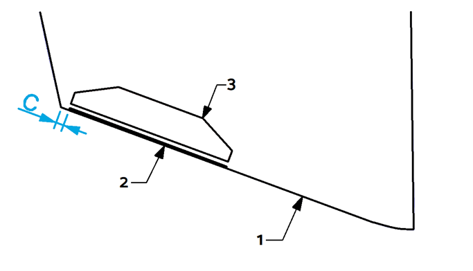
It is possible to have an installation where the Controller is mounted too far outboard causing water flowing around the hull side to interfere with the Controller and substantially reduce performance.
To avoid this issue, the Controller should be mounted at least 1.5 in. (38 mm) inboard of the hull side, as shown below.
Engine Spacing
NOTE: Seakeeper has performed successful testing with Seakeeper Ride overlapping propellers significantly further than indicated below; however, because of the infinite variables (engine height, engine trim, engine longitudinal offset from Seakeeper Ride Controllers, propeller selection, propeller rotation, sea conditions, loading conditions, vessel characteristics, and more) which impact the interaction between Seakeeper Ride and propulsors, Seakeeper cannot provide more specialized guidance or blanket recommendation to install with more propeller overlap than indicated below. If the Builder, Owners, or Operators choose to install the Seakeeper Ride Controllers with more propeller overlap than indicated in the figure below, it may result in rpm/coolant fluctuation and/or engine faults. Please see the Operation Manual for additional detail on Seakeeper Ride’s potential impacts to propulsors.
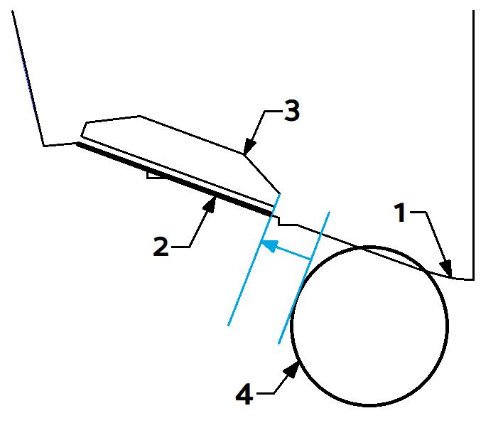
Because the Controllers have the potential to change water flow into the boat’s propellers, the Controllers should be mounted as far from the propellers as possible. It is recommended that the inner edge of the Controller be mounted outboard of the diameter of the propeller tip (see the figure below). The line defining this instruction is the tangent line to the diameter of the propeller tip on the outboard side, perpendicular to the deadrise. Label 4 indicates the diameter of the propeller tip.
Note: Any obstructions preventing the installation of the Controllers or beyond the dimensions specified must be removed before continuing with the installation of Seakeeper Ride.
Pontoon Boats
The Seakeeper Ride Controllers should be mounted centered on the two outer pontoons regardless of whether it is a pontoon or tritoon boat. Mount the Controllers horizontal or parallel to the ground when viewed from the rear. Mount the Controllers parallel to the original bottom running surface of the pontoons when viewed from the side (see Figure 19).
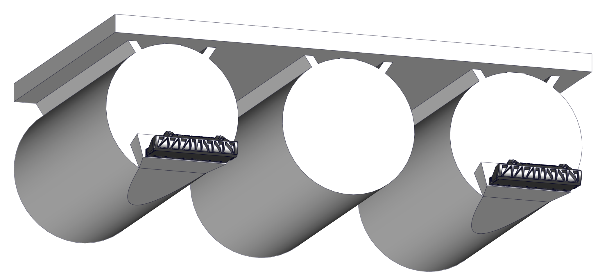
Because pontoon boats generally do not have a flat transom surface and the running surface is essentially a very low radius convex deadrise (Convex Deadrise in Section 5.2.), modifications to the pontoons will almost certainly be necessary to create a flat mounting surface and relatively straight bottom with developed flow. Any modifications must be structural to withstand the extremely high loads Seakeeper Ride generates (Section 2.2. Forces Applied to the Hull). Modifications must be compatible with the original consturction of the pontoons.
Potential options for modifying pontoons to accept Seakeeper Ride include:
- Additive – Create a standoff or bracket with one side that matches the shape of the pontoon and gradually transitions to the shape of the Controller.
- Subtractive – Remove and replace material on the back and bottom of the pontoon at angles that create a gradual transition to the Controller’s width and straightness and create a flat mounting surface on the transom.
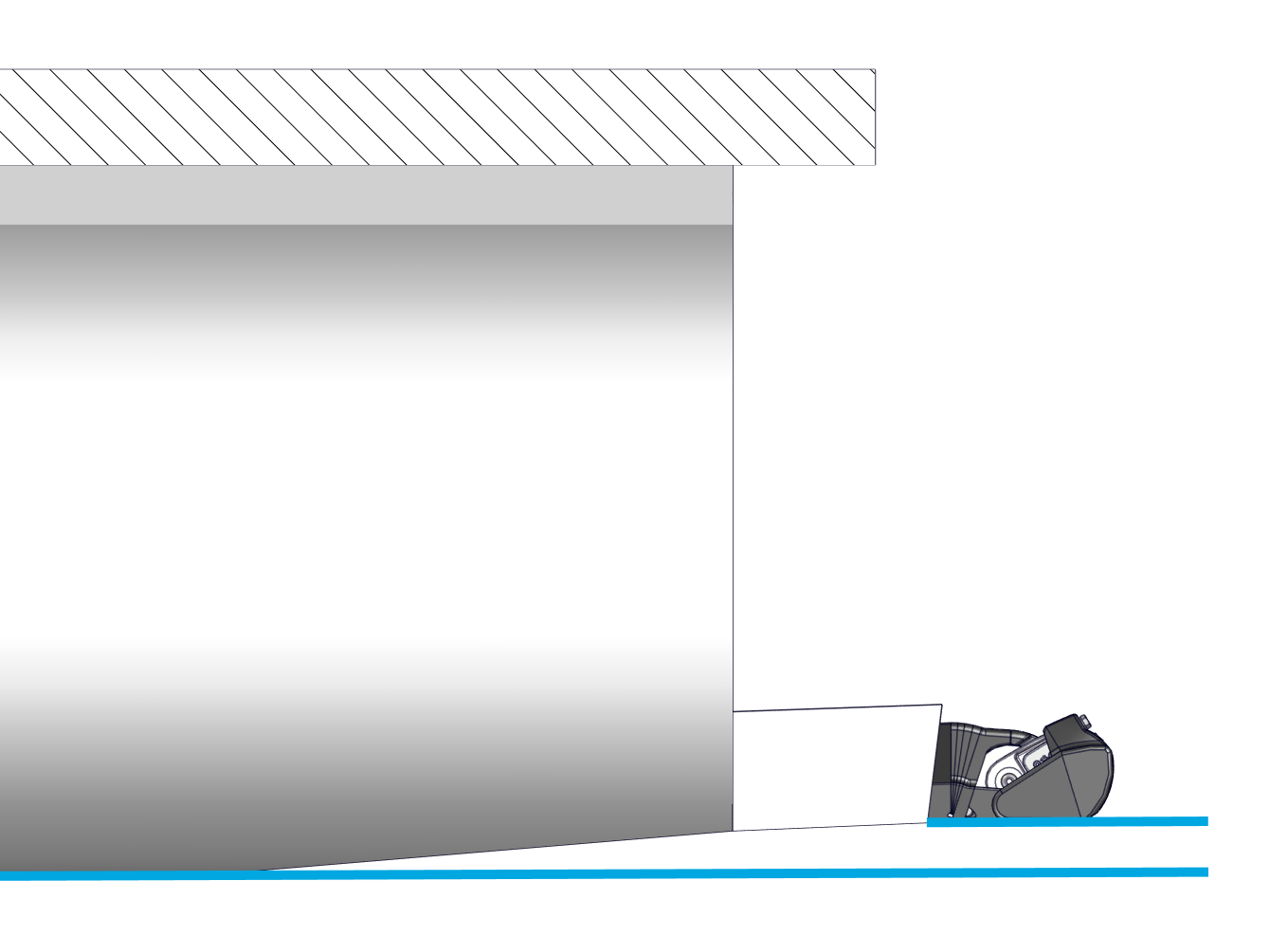
- Combination – Options 1 and 2 may be combined by cutting a flat transom and hull bottom with partial shape and flow transition and completing it with a bracket that is the correct size and distance to supply fully developed flow to the Controller. Combination modification example is shown in the figure above.
Important Notes:
- Running characteristic considerations – When making pontoon modifications, consider the permanent effect it will have on the running characteristics of the boat. Adding material will generally add buoyancy and bow down attitude. Removing material will generally remove buoyancy and add bow up attitude.
- Gradual Transition – Previous testing performed by Seakeeper suggests at least 12.0 in. (30.5 cm) for-aft for every 1.0 in. (2.5 cm) of height to ensure fully developed flow to the Controllers. In other words, at least a 12/1 slope is required when viewed from the side of the boat. Failure to transition gradually will result in substantially reduced performance.
- Transom Angle – The transom must be at an angle compatible with the Controller Wedge Pack adjustment limits (See Table 2 in Section 6.1.). The transom angle CANNOT be 90 degrees.