Mechanical Installation Manual (450, 525, 600)
6.1. Measurement Steps
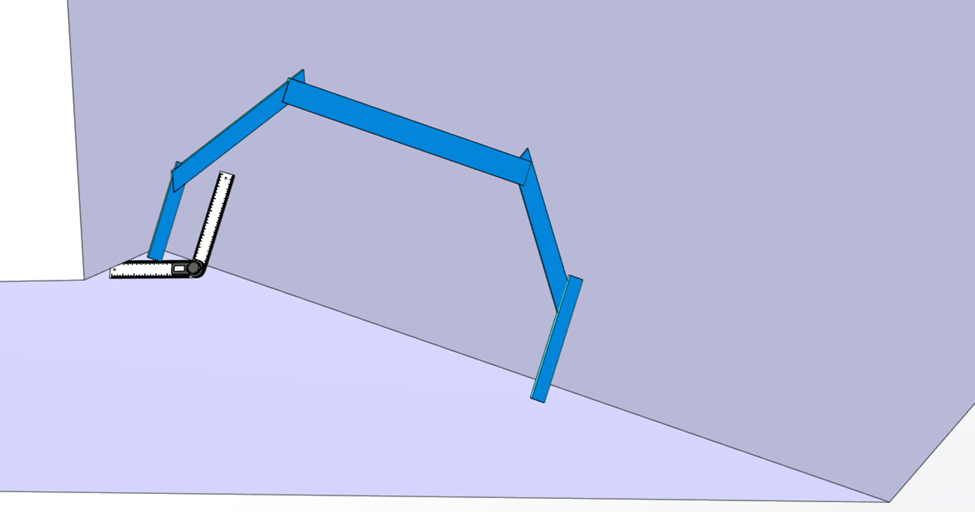
- Using the selected Controller locations from Section 5, measure the angle with a digital protractor from the running surface to the transom, perpendicular to the deadrise. See the figure below for an example of the measurement on the port Controller, outboard location.
- Measure the inboard and outboard ends of the port Controller area and use the larger angle in the following Sections. Round up to the nearest degree.
- Measure inboard and outboard ends of the starboard Controller area and use the larger angle in the following Sections. Round up to the nearest degree. As with every step, repeat measurement process for both port and starboard sides. Note: It is possible to find different angles between port and starboard side of the hull.
- Determine the number of wedges required for each Controller’s Wedge Pack using the transom angle measured in previous sections and Table 2 – Transom Angle and Wedge Plates.

The transom and Wedge angles indicated in the Table 2 are the maximum range of the product. If the boat’s transom angle is outside the range of Table 2, do not add or remove more wedges to accommodate the different angle. The hardware is rated only for the amount of Wedge Plates outlined in the table below to maintain full structural integrity.
Instead, build out the transom – using materials consistent with the transom structure – to change the angle of the transom in the general footprint of the Transom Plate as shown in blue in Figure 27. When adding material, match the transom’s structural strength. Please consult your Naval Architect or Marine Engineer to verify the structural integrity of the added materials.
Table 2 – Wedge Plates Based on Transom Angle
| Wedge Plates | |||||
| Transom Angle | Measured Angle | 3 Degree | 4 Degree | 5 Degree | Top Bolt Length |
| 68 | 112° | 1 | 50 mm | ||
| 69 | 111° | 1 | 50 mm | ||
| 70 | 110° | 1 | 50 mm | ||
| 71 | 109° | 2 | 60 mm | ||
| 72 | 108° | 1 | 1 | 60 mm | |
| 73 | 107° | 1 | 1 | 60 mm | |
| 74 | 106° | 1 | 1 | 60 mm | |
| 75 | 105° | 2 | 60 mm | ||
| 76 | 104° | 1 | 2 | 60 mm | |
| 77 | 103° | 1 | 1 | 1 | 60 mm |
| 78 | 102° | 1 | 2 | 60 mm | |
| 79 | 101° | 1 | 2 | 60 mm | |
| 80 | 100° | 2 | 1 | 1 | 60 mm |
| 81 | 99° | 2 | 2 | 60 mm | |
| 82 | 98° | 1 | 1 | 2 | 60 mm |
| 83 | 97° | 2 | 2 | 60 mm |