Mechanical Installation Manual (450, 525, 600)
9. Test Fit
Test Fit Introduction
To ensure proper fit of the equipment, the Seal Plate must be temporarily installed.
Note: While test fitting, verify that the nuts receiving the bolts are lined up correctly. Pay particular attention to the square nuts on the sides or ‘wings’ of the Transom Plate.
9.1. Test Fit the Seal Plate
- Hang the Wedge Pack on the positioning screws. Align the bottom surface of the Wedge Pack Assembly with the deadrise as indicated in Section 5.
- When aligned, tighten the positioning screws to hold the Wedge Pack in place.
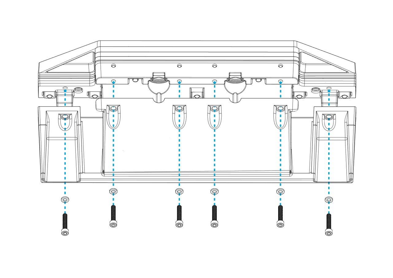
- Add the Seal Plate to the assembly to check its position as indicated in Section 5. Insert the six (6) M6-1.0 x 30 mm bolts and washers to hold the Seal Plate, as shown below after applying Vibra-Tite thread locker to bolts. (600 mm Controllers will have eight [8] bolts and washers.) Note: Apply thread locker, but do not apply the final torque during this step.
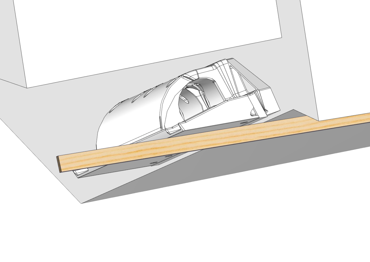
- Using a straight edge, verify that the Seal Plate is between flush and up 1/8″ above the hull bottom in the desired location as shown above. Due to different hull shapes and features, the Seal Plate may not be flush with the hull bottom across its full span. However, make sure no part of the Controller is below the RRL. For more information, refer to Section 5.
- If the Seal Plate is not flush in the location needed, repeat Section 7, modifying the number of Wedge Plates until the correct angle has been achieved. Note: When removing and re-inserting bolts, be cautious of debris on the hardware that can cause it to bind, including old thread locker, dirt, etc.
- Once fit is satisfactory, mark the alignment with a writing utensil on inboard and outboard sides of the Transom Plate to make the final mounting easier.
- Remove the Seal Plate from the Wedge Pack using the six (6) M6-1.0 x 30 mm bolts and washers (eight [8] on a 600 mm Controller).