Mechanical Installation Manual (450, 525, 600)
10. Drill for Cable Entry
Drill for Cable Entry Introduction
The Seakeeper Ride system can be installed on a variety of boats with different space and size constraints for the Actuator Cable entry. Based on the selection of cable entry determined in Section 5.7, follow either Section 10.1 for Concealed Cable Entry or Section 10.2 for Exposed Cable Entry.
10.1. Concealed Cable Entry
The cable routing can be concealed if the hull structure allows for it. Follow this procedure for mounting the supplied protective conduit for the Actuator cable.
- Check for available space on the interior of the hull and clean access to the transom prior to starting the Concealed Cable Entry procedure. Verify there is no structure or cable in the way of either inboard or outboard oval hole location of the Wedge Pack Assembly.
- Assemble the Drill Guide by placing the Drill Guide Tube inside of the follower with the rounded part of the tube on the outer diameter of the follower, as shown below. The tube should telescope in and out of the follower freely.

- Leave the Wedge Pack in place as fitted during Section 9.
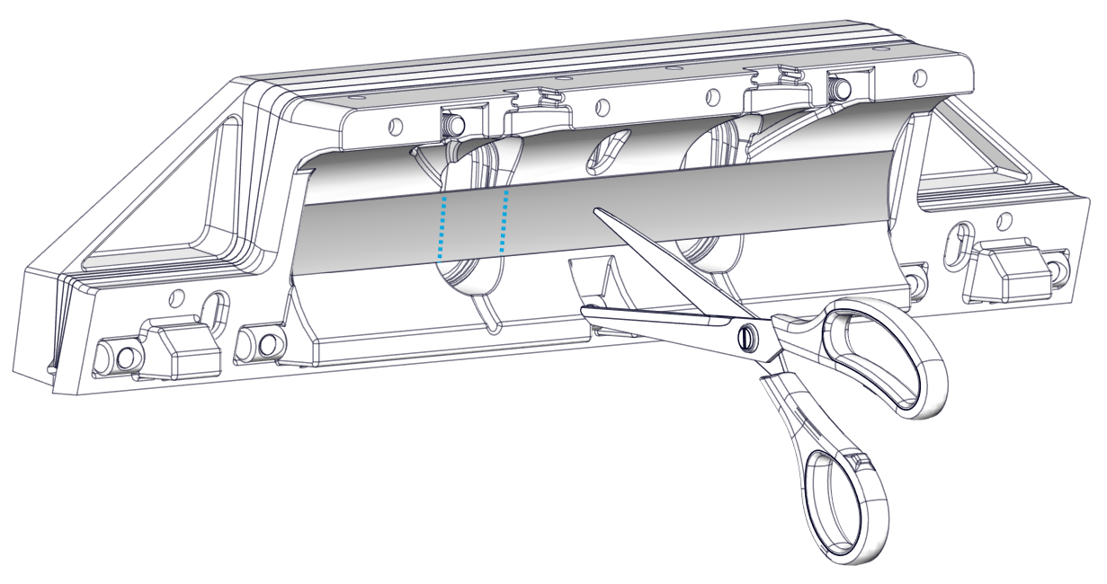
- If the Friction Gasket is covering the portion where the Cable Gland tube will be, cut away at the opening using a razor blade or scissors.
- Place the Drill Guide Assembly in one of the oval cable ports in the Wedge Pack Assembly as shown below.
- The inboard or outboard oval cable port in the Wedge Pack Assembly can be used depending on available inboard space.

- Press the face of the Drill Guide flush with the transom of the boat. Use this to create a 1/4 in. (6.4 mm) pilot hole in the transom.
- Remove the Drill Guide.
- Loosen the positioning screws that are holding the Wedge Pack in place, then remove the Wedge Pack Assembly.
- Drill out the pilot hole to match the diameter of the Cable Gland with a 3/4 in. (19 mm) drill bit.
- Apply a liberal amount of sealant on the outer diameter of the Cable Gland tube (See figure below, Left). Install the Cable Gland tube from the inboard side of the transom.
- Apply more sealant where the tube meets the outboard side of the transom (See figure below, Right).
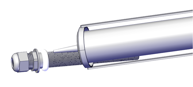
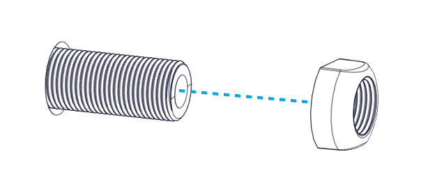
- Install the Nut on the outboard side of the transom. Tighten until the Nut contacts the transom. Do not overtighten.
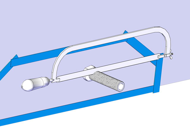
- Cut off the excess threads on the outboard side off using a hacksaw or oscillating tool.
10.2. Exposed Cable Entry
In the instance in which the Actuator cable will be exposed, follow this procedure for mounting the supplied protective conduit for the Actuator cable.
Note: The shape of the Outer Cable Guide is designed to cover most holes left by previous trim tabs when using the same cable hole.
- Check for structural clearances and rigging inside the hull before proceeding with drilling holes for the cable route in the transom.
- Determine the ideal location where the cable will penetrate the hull based on Section 5.7
- Using 3/4 in. (19 mm) drill-bit or hole saw, drill a hole through the transom.
- Apply a liberal amount of sealant on the outer diameter of the gland. Install the Cable Gland Tube from the inside (Figure 52 – Sealant Application to Cable Gland).
- Note: Though not the preferred method, if circumstances dictate, the Cable Gland Tube CAN be inserted from the outside when doing exposed cable entry. However, the Nut will need to be installed from the inside, and the Cable Guide and Cover will not be able to be installed.
- Install the Nut on the outboard side of the transom. Tighten until the Nut contacts the transom. Do not overtighten (Figure 52 – Outboard Cable Gland Nut Installation).
- Cut off the excess threads on the outboard side using a hacksaw or oscillating tool (Figure 54 – Cable Gland Trimming).
- Hold the Inner Cable guide up to the Cable Gland in the desired mounting location. Mark the locations of the two (2) mounting screws and drill 3/32 in. (2.4 mm) pilot holes in these locations.
- Inject sealant in both pilot holes. Use a screwdriver to install the two (2) No. 8 x 1-1/2 in. screws to mount the Inner Cable Guide.