Mechanical Installation Manual (450, 525, 600)
12. Actuator and Blade Installation
Actuator and Blade Installation Introduction
The final stages of installation are differentiated by the cable entry into the hull. If you are following a concealed cable entry, follow the procedure detailed in Section 12.1. For exposed cable entry, follow procedure in Section 12.2.
Note: Do not bend the Actuator Cable at a radius smaller than 50 mm (1.97 in.) to avoid damaging the cable. Do not lift the Actuator by the cable when removing from the box or anytime carrying.
12.1. Concealed Cable Entry

ATTENTION: The following procedure must be followed with careful attention to the sequence of bolts, correct thread locker and correct torque applied to the bolts. Not following the procedure correctly can result in poor Ride performance.
ATTENTION: DO NOT pickup the Actuator by the cable or allow it to hang by the cable. Doing so could compromise to the watertight seal of the Actuator and cause system malfunction.
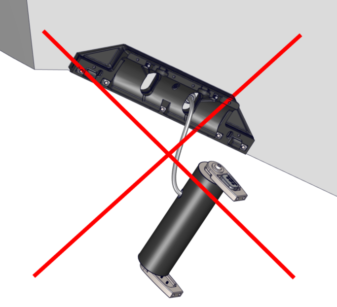
Note: The Cable Gland must have the black rubber grommet in place to properly seal. Ensure the grommet is present and remains in place while inserting the Actuator cables. The outside of the cable must be clean of debris, dust, adhesives, etc. to properly seal. Do not allow acetone to come in contact with the Controller Cable Gland Sealing Nut.
1. Align the Actuator so the cable passes through the hole in the Wedge Pack Assembly and the Cable Gland. Feed the Actuator Cable through the Cable Gland and remove as much slack from the outboard side as possible.
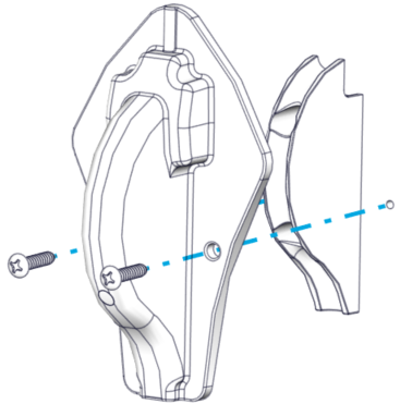
2. Set the Seal Plate over the Actuator, secure it in place with two (2) M6-1.0 x 30mm Socket Head Cap Screws in wing positions. Apply Vibra-Tite 132 thread locker to the screws. Torque screws to 60 in-lbs (6.8 N-m). (Note: The Seakeeper Ride 600 system will have four (4) screws).
Apply Torque two (2) times to ensure fasteners are seated.

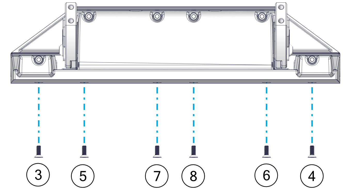
3. Secure the Seal Plate bottom with six (6) M6-1.0 x 16 mm Flat Head Socket Cap Screws from the bottom edge of the Seal Plate and apply Vibra-Tite 132 thread locker to the screws. Torque screws to 60 in-lbs (6.8 N-m). (Note: The Seakeeper Ride 600 system will have eight (8) screws).
Apply Torque two (2) times to ensure fasteners are seated.
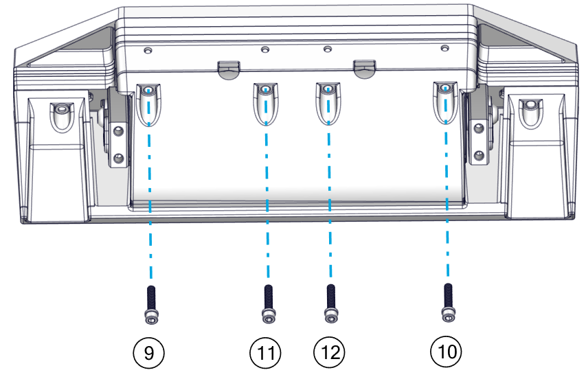
4. Secure the Seal Plate top with the four (4) M6-1.0 x 30mm Socket Head Cap Screws from the top face of the Seal Plate, and apply Vibra-Tite 132 thread locker to the screws. Torque screws to 60 in-lbs (6.8 N-m).
Apply Torque two (2) times to ensure fasteners are seated.
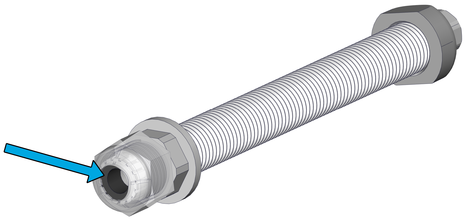
5. Tighten the Cable Gland on the inboard side of the transom. The Cable Gland should be snug to prevent leaking, but do not overtighten. Gently pull on the cable to ensure there is no movement and prove it is sealing securely.
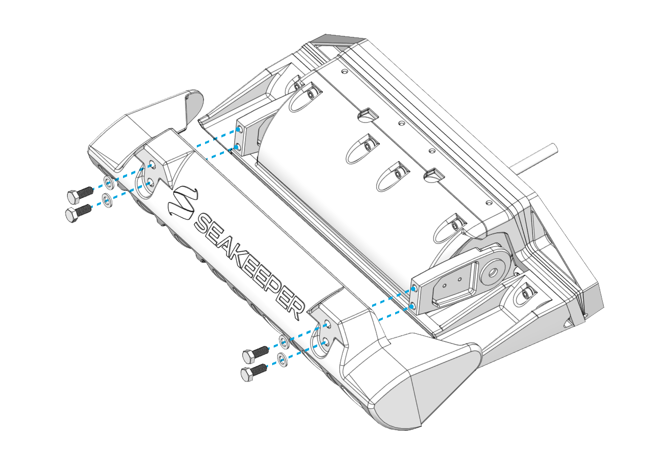
6. Install the Blade to the Actuator Arms using the four (4) M8-1.25 x 20 mm screws and their washers. Apply Vibra-Tite 132 thread locker to the screws. Torque these four (4) bolts to 80 in-lbs (9.0 N-m) in an ‘X’ pattern.
- Once installed, push the Blade all the way down and verify that the Blade is not contacting the Seal Plate. There should be a small, even gap between the Blade and the Seal Plate.
- Before torquing, the Blade can be slid up and down slightly to bring it closer and farther away from the Seal Plate, respectively. If the Blade is rubbing and creating friction against the Seal Plate, or if the gap appears too large, adjust the Blade accordingly. Contact Seakeeper if there are still concerns with Blade gap tolerance after following these instructions.
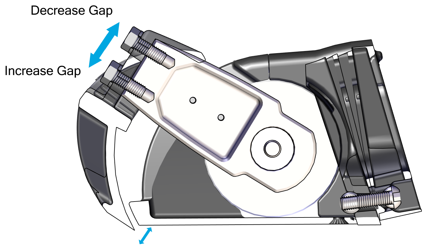
Note: Maintaining this gap between the Blade and Seal Plate is critical to maintaining factory tested failure mode performance. If the gap between the Blade and Seal Plate is too large, system performance will fall off. If the Blade contacts the Seal Plate, the friction will slow down the system’s response time, also reducing performance.
To maintain the factory fitment:
- Do not apply anti-fouling coating to the surfaces between the Blade and Seal Plate in order to avoid changing the fit of those parts.
- Always keep the surfaces between the Blade and Seal Plate clean and free from debris, including naturally occurring debris (such as marine debris) and other debris (such as paint or coating.
- When repairing or replacing any components on the Controller, confirm that the Blade rotates by hand. Resistance will be felt from the Actuator, but there must be no additional grinding or friction inhibiting movement.
- Allow the adhesive to cure fully before sea trialing the boat.

Each adhesive has a full cure time or close to full cure, which must be met before any load is applied. After the installation is complete, before sea trialing the boat, wait at least the full cure time advertised by the adhesive manufacturer in the temperature during the install, or 24 hours, whichever is greater. Colder temperatures increase fixture time and cure time. (In very cold climates, the adhesive may need to cure for multiple days before sea trialing.) Refer to technical data sheets (TDS) and manufacturer recommendations for the particular adhesive being used.
12.2. Exposed Cable Entry
 ATTENTION: The following procedure must be followed with careful attention to the sequence of bolts, correct thread locker and correct torque applied to the bolts. Not following the procedure correctly can result in poor Ride performance.
- Install the Cable Guide Support in the groove in the Seal Plate.
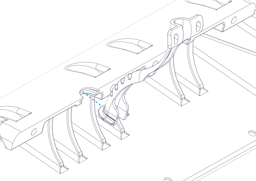
2. Install the Actuator in the Seal Plate. Route the Actuator Cable through the Cable Guide Support.
3. Set the Seal Plate back overthe Actuator, secure it in place with two (2) M6-1.0 x 30mm Socket Head Cap Screws in wing positions. Apply Vibra-Tite 132 thread locker to the screws. Torque screws to 60 in-lbs (6.8 N-m). (Note: The Seakeeper Ride 600 system will have four (4) screws).
Apply Torque two (2) times to ensure fasteners are seated.
4. Secure the Seal Plate bottom with six (6) M6-1.0 x 16 mm Flat Head Socket Cap Screws from the bottom edge of the Seal Plate and apply Vibra-Tite 132 thread locker to the screws. Torque screws to 60 in-lbs (6.8 N-m). (Note: The Seakeeper Ride 600 system will have eight (8) screws). Torque of 60 in-lbs (6.8 N-m) is 20% greater than previously specified.
Apply Torque two (2) times to ensure fasteners are seated.
5. Secure the Seal Plate top with the four (4) M6-1.0 x 30mm Socket Head Cap Screws from the top face of the Seal Plate and, apply Vibra-Tite 132 thread locker to the screws. Torque screws to 60 in-lbs (6.8 N-m).
Apply Torque two (2) times to ensure fasteners are seated.
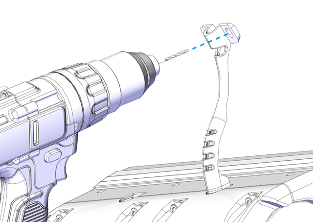
6. Mount the Cable Guide Support in line with the natural path of the Actuator Cable to the transom. Pre-drill two (2) mounting screw pilot holes using a 3/32 in. (2.4 mm) bit. Inject sealant into the holes. Insert two (2) No. 8 x 0.75 in. screws and tighten with a Phillips head screwdriver.
- Route the Actuator cable over the Inner Cable Guide. Feed as much cable as possible through the Cable Gland Tube.
- Tighten the Cable Gland around the Actuator Cable on the inboard side of the transom (See Figure 67 – Cable Gland Installation Inboard of Transom). The Cable Gland should be snug to prevent leaking, but do not overtighten. Gently pull on the cable to ensure there is no movement and prove it is sealing securely. Note: The Cable Gland must have the rubber grommet in place to properly seal. The outside of the cable must be clean of debris, dust, adhesives, etc. to properly seal. Do not allow acetone to come in contact with the Controller Cable Gland Sealing Nut.
- Place the Outer Cable Guide over the Inner Cable Guide. Mark the location of the two (2) mounting screw holes. Drill 1/8 in. (3.2 mm) pilot holes in these two (2) locations.
- Note: The shape of the Outer Cable Guide is designed to cover most holes left by previous trim tabs when using the same cable hole.
- Inject sealant into the pilot holes for the mounting screws for the Outer Cable Guide. Using a Phillips head screwdriver, install the two (2) No. 10 x 1 in. mounting screws into the hull and hand-tighten.
- Install the Blade to the Actuator Arms using the four (4) M8-1.25×20 mm screws and their washers. Apply Vibra-Tite 132 thread locker to the screws. Torque these four (4) bolts to 80 in-lbs (9.0 N-m) in an ‘X’ pattern (Figure 68 – Blade Installation).
- Once installed, push the Blade all the way down and verify that the Blade is not contacting the Seal Plate. There should be a small, even gap between the Blade and the Seal Plate.
- Before torquing, the Blade can be slid up and down slightly to bring it closer and farther away from the Seal Plate, respectively. If the Blade is rubbing and creating friction against the Seal Plate, or if the gap appears too large, adjust the Blade accordingly. Contact Seakeeper if there are still concerns with Blade gap tolerance after following these instructions. (Figure 69 – Blade Gap Adjustment)
Note: Maintaining this gap between the Blade and Seal Plate is critical to maintaining factory tested failure mode performance. If the gap between the Blade and Seal Plate is too large, system performance will fall off. If the Blade contacts the Seal Plate, the friction will slow down the system’s response time, also reducing performance.
To maintain the factory fitment:
- Do not apply anti-fouling coating to the surfaces between the Blade and Seal Plate in order to avoid changing the fit of those parts.
- Always keep the surfaces between the Blade and Seal Plate clean and free from debris, including naturally occurring debris (such as marine debris) and other debris (such as paint or coating.
- When repairing or replacing any components on the Controller, confirm that the Blade rotates by hand. Resistance will be felt from the Actuator, but there must be no additional grinding or friction inhibiting movement.
- Allow the adhesive to cure fully before sea trialing the boat.
Each adhesive has a full cure time or close to full cure, which must be met before any load is applied. After the installation is complete, before sea trialing the boat, wait at least the full cure time advertised by the adhesive manufacturer in the temperature during the install, or 24 hours, whichever is greater. Colder temperatures increase fixture time and cure time. (In very cold climates, the adhesive may need to cure for multiple days before sea trialing.) Refer to technical data sheets (TDS) and manufacturer recommendations for the particular adhesive being used.