Mechanical Installation Manual (450, 525, 600)
5.7. Cable Entry
In the final details of the installation, the cable that powers and drives the Controllers must pass through the transom of the hull. The location for cable penetration will be based on available access to the transom on the interior.
Concealed Cable Entry
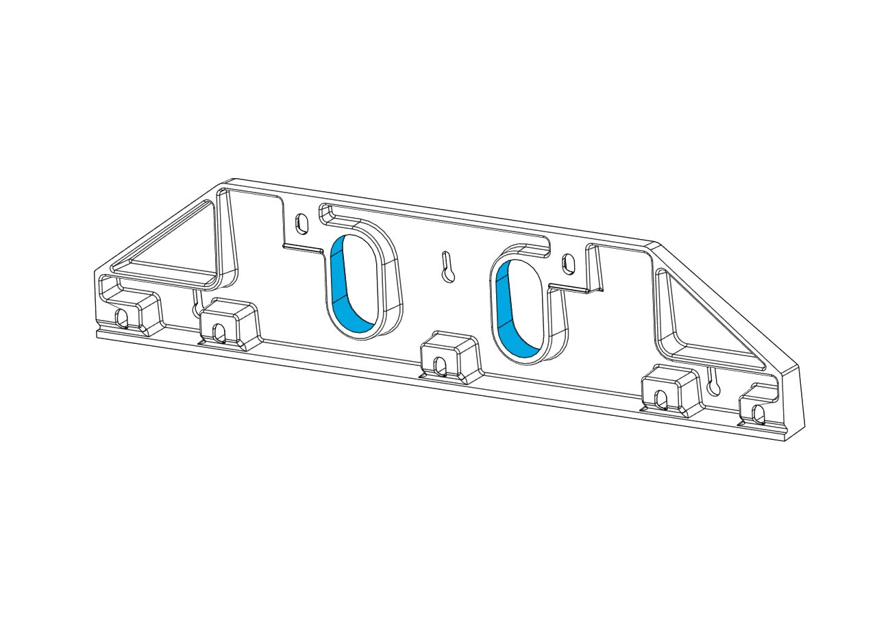
For concealed cable entry, route through either of the oval holes of the Transom Plate (highlighted in blue in the figure below). To utilize either location, you must be able to reach the hole from the inside to tighten the supplied cable gland and prevent water entering the hull.

As an example for internal routing, the figure below depicts a stringer shown with dotted lines that is preventing use of the inboard cable penetration. In this example, the outboard cable pass-through is available as indicated by the blue arrow. This can only be used if there is access on the interior side of the penetration.

Exposed Cable Entry
Locations outside the Transom Plate can be used as well. If the cable penetration location is below the waterline, the supplied cable gland must be used to ensure a watertight hull after the penetration.
This cable penetration method can be used in locations above the waterline as well.
Cable Lengths
In all cases, the supplied cable for the Controllers is limited to 10 ft (3 m). Carefully consider the cable routing and location of the Distribution Module to ensure both cables can connect to the Distribution Module.