Mechanical Installation Manual (450, 525, 600)
4. Inventory Parts
Please review all parts included before proceeding. The following figure and table describe all parts included in the assembly. Review parts and ensure all parts are present before starting the installation procedure.
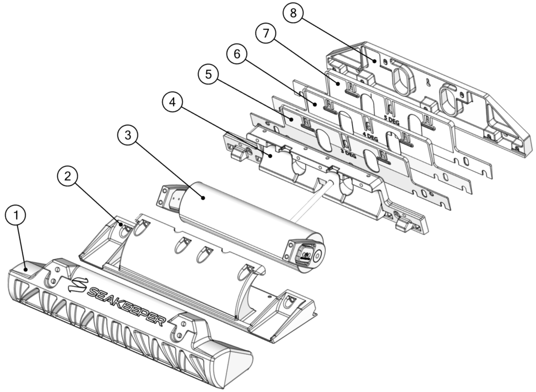
- Blade
- Seal Plate
- Actuator
- Actuator Plate
- 3 Degree Wedge Plate
- 4 Degree Wedge Plate
- 5 Degree Wedge Plate
- Transom Plate
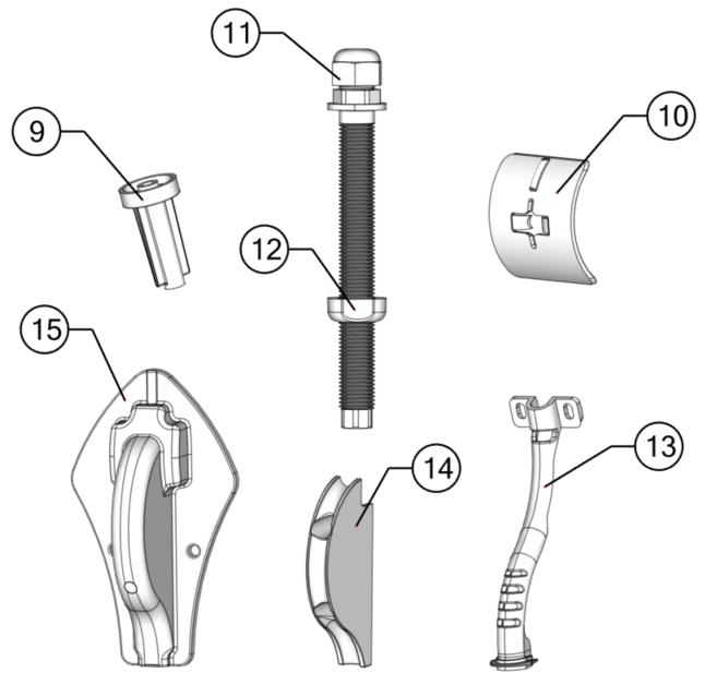
- Drill Guide Tube
- Drill Guide Follower
- Cable Gland Tube
- Cable Gland Nut
- Cable Support Guide
- Inner Cable Guide
- Outer Cable Guide

ATTENTION: DO NOT pickup the Actuator by the cable or allow it to hang by the cable. Doing so could compromise to the watertight seal of the Actuator and cause system malfunction.
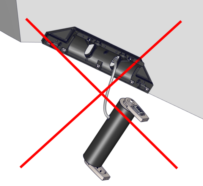
Table 1 – Mechanical Installation Hardware
| Wedge Pack Hardware | Positioning Screws | |||
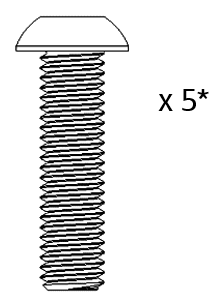 M8-1.25 x 30 mm Button Head Bolt | 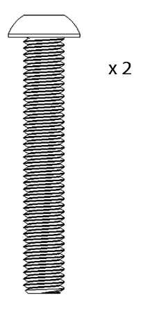 M8-1.25 x 50 mm Button Head Bolt | 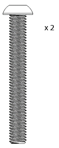 M8-1.25 x 60 mm Button Head Bolt | 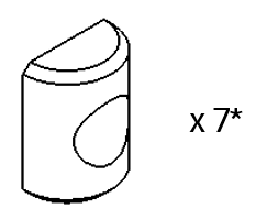 M8 Half Cylinder Washer 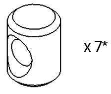 M8 Cylindrical Nut | 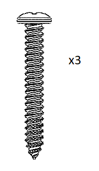 Phillips No. 8 x 1.25 in. Screw |
| Seal Plate Hardware | Blade Hardware | |||
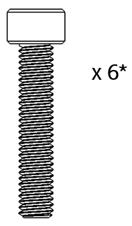 M6-1.0 x 30 mm Socket Head Cap Screw |  M6 Washer | 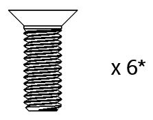 M6-1.0 x 16 mm Flat Head Socket Cap Screw | 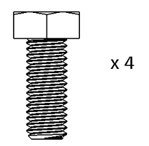 M8-1.25 x 20 mm Hex Head Screw |  M8 Washer |
| Cable Routing Hardware | ||||
 Phillips No. 8 x 0.75 in. Screw |  Phillips No. 8 x 1.5 in. Screw | 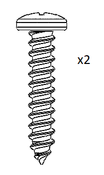 Phillips No. 10 x 1.0 in. Screw |
*Item count given for 450 mm and 525 mm systems. 600 mm systems will have two (2) additional pieces for this hardware type.