Seakeeper 5 / 6 Installation Manual (90402-5) 6/5-233-5847 to Current
2.4 Bolt-In Installation
2.4.1 Preparation of Vessel Structure
Seakeeper provided mounting hardware is intended to apply to typical installation arrangements. However, each installation, especially custom aftermarket foundations, should be thoroughly reviewed to ensure the provided hardware meets the required thread engagement for the Seakeeper unit being installed. The mounting bolt thread engagement requirements are outlined in the Installation Manuals and Installation Details Drawings for each Seakeeper model. This also applies to Seakeeper model adapter kits and OEM built frames where the bolt hole depth should be checked to ensure the bolts will not bottom, preventing the bolts from achieving the intended preload.
The Seakeeper supporting structure should be parallel to the vessel waterline, with up to 2 degrees allowance for trim.
In addition, the four areas on top of the beams on which the feet of the Seakeeper foundation and isolation gaskets will rest need to be co-planar within .06 in. (1.5 mm) to minimize potential distortion of Seakeeper support frame when installed. The isolation gaskets are only used when the Seakeeper 6 is mounted to a dissimilar metal structure.
When the Seakeeper provided hardware is not appropriate, the bolt specification (diameter and thread pitch) and grade should be matched in the required length and used with the Seakeeper provided washers. Mounting bolts should always be torqued to the Seakeeper specification. All Seakeeper provided bolts are metric course thread. Hardware specifications are also listed in the Installation Manuals and Installation Details Drawings.
Refer to Seakeeper Drawing No. 90398 – Seakeeper 5/6 Bolt-In Installation Details. Important dimensional and load information is given in this drawing that will impact the design details of the structure that will receive the Seakeeper. It is assumed that a proper structural analysis has been performed for the hull structure to which the Seakeeper will be fastened to ensure proper strength margins for the loads the Seakeeper will create during operation.
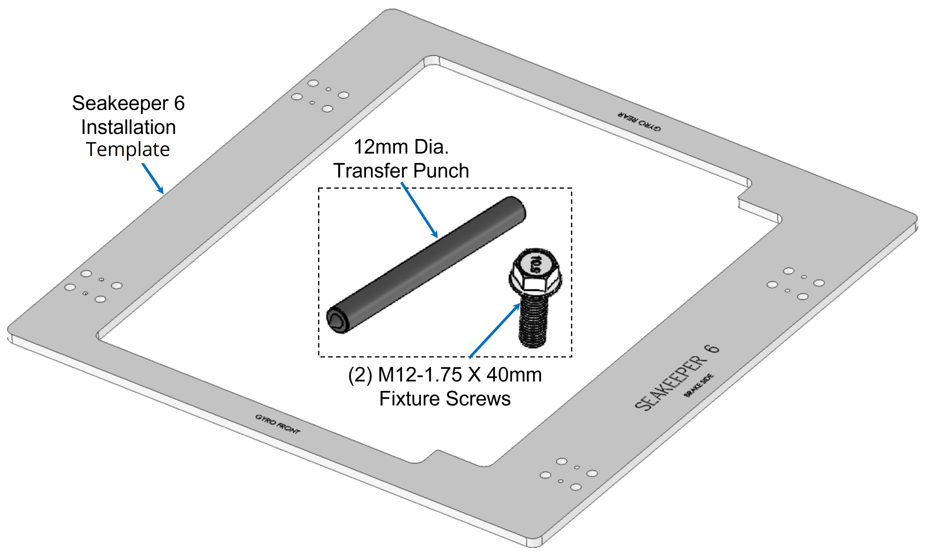
Seakeeper provides an installation template kit, P/N 90392, which contains four plates that mimic the mating surfaces of the four feet located on the Seakeeper’s foundation. These plates have 4 holes located at the same centers as the mounting holes on the Seakeeper. The fixture locates the hole patterns at the proper spacing both in the forward-aft direction and the port-starboard direction. See Figure 5 below. Once assembled, the fixture can be used to check clearances and alignment of the hull structure.
Note: Do NOT use the installation fixture to establish Seakeeper envelope dimensions. Refer to Drawing No. 90398 – Seakeeper 6 Bolt-In Installation Details, for envelope dimensions. A 3-D model of the Seakeeper is available on the Seakeeper website (www.seakeeper.com) to aid in designing the Seakeeper foundation and the space around the Seakeeper.
NOTE: MAKE SURE NO OBSTRUCTIONS FROM THE HULL STRUCTURE CAN BE SEEN WITHIN THE INSIDE OF THE INSTALLATION TEMPLATE KIT (INSIDE THE MARKED RED LINES). REFERENCE SEAKEEPER DRAWING NO. 90398 – SEAKEEPER 6 BOLT-IN INSTALLATION DETAILS.
CAUTION: Tight clearances from cable guide bands and brake side gimbal shaft to hull structure. See below for brake side gimbal shaft clearance. See above figure for dimensions and reference Seakeeper Drawing No. 90398 – Seakeeper 6 Bolt-In Installation Details, for complete Seakeeper envelope.
2.4.2 Transfer of Holes to Boat Structure
- Lower assembled fixture onto hull structure.
- The four areas where the feet of the Seakeeper will rest should be coplanar to within .06 in. (1.5 mm). See figure below.
- Align fixture in desired location and transfer holes from fixture plate to the foundation structure. Note that holes in fixture plate are ø0.487 in. (12 mm). A transfer punch is supplied with installation template kit, P/N 90392.
Figure 8 – Bolt-In Hole Transfer Fixture
2.4.2.1 Blind Hole Installation
- Remove Template Fixture and drill sixteen(16) 0.49 in. (12.5 mm) holes perpendicular to the vessel structure to a minimum depth of 0.94 in. (24 mm). Take special care to drill perpendicular to mounting surface. A drill guide is recommended. Remove any impeding obstructions.
- Tap drilled holes for helical thread inserts per documentation accompanying helical threaded inserts.
- Install sixteen (16) M12-1.75 X 18 mm threaded inserts into holes in hull structure at drilled and tapped locations using threaded insert manufacturer provided installation tool.
- Remove threaded insert prong / tang after threaded inserts are installed.
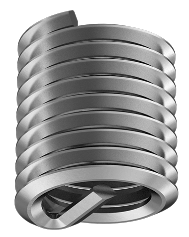
M12-1.75 X 18 mm
2.4.2.2 Through-Bolt Installation
- Remove Template Fixture and drill sixteen (16) 0.512 in. (13 mm) ø holes perpendicular to the vessel structure. Take special care to drill perpendicular to mounting surface. A drill guide is recommended.
2.4.3 Installation of Seakeeper
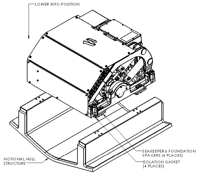
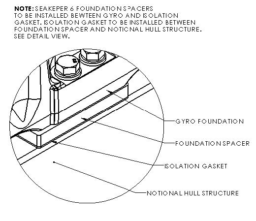
- Locate and position four foundation spacers (P/N 11241) onto hull structure.
- For dissimilar metal foundations, locate and position four isolation gaskets (P/N 11145) onto foundation beams and apply a small bead of marine sealant (SILI-THANE 803 or equivalent) between both mating surfaces of each isolation gasket where it contacts the beam and the Seakeeper.
- Lower Seakeeper into position onto foundation beams and align over drilled holes.
- Install Mounting Bolts:
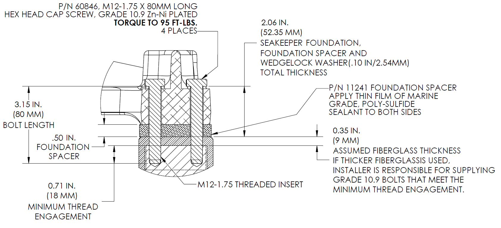
- For Blind-Hole installations (P/N 90400 – Seakeeper 6 / 5 Bolt-In Kit), install the Seakeeper supplied M12-1.75 fasteners to maintain a minimum thread engagement of 0.71 in. (18 mm). Apply a moderate coat of nickel-based anti-seize (e.g., SAF-T-EZE nickel grade anti-seize, SBT-4N or equivalent) to the threads of each bolt and include a small bead of marine grade sealant (e.g., SILI-THANE 803 or equivalent) under each bolt head and washer before installation. See Figure 11.
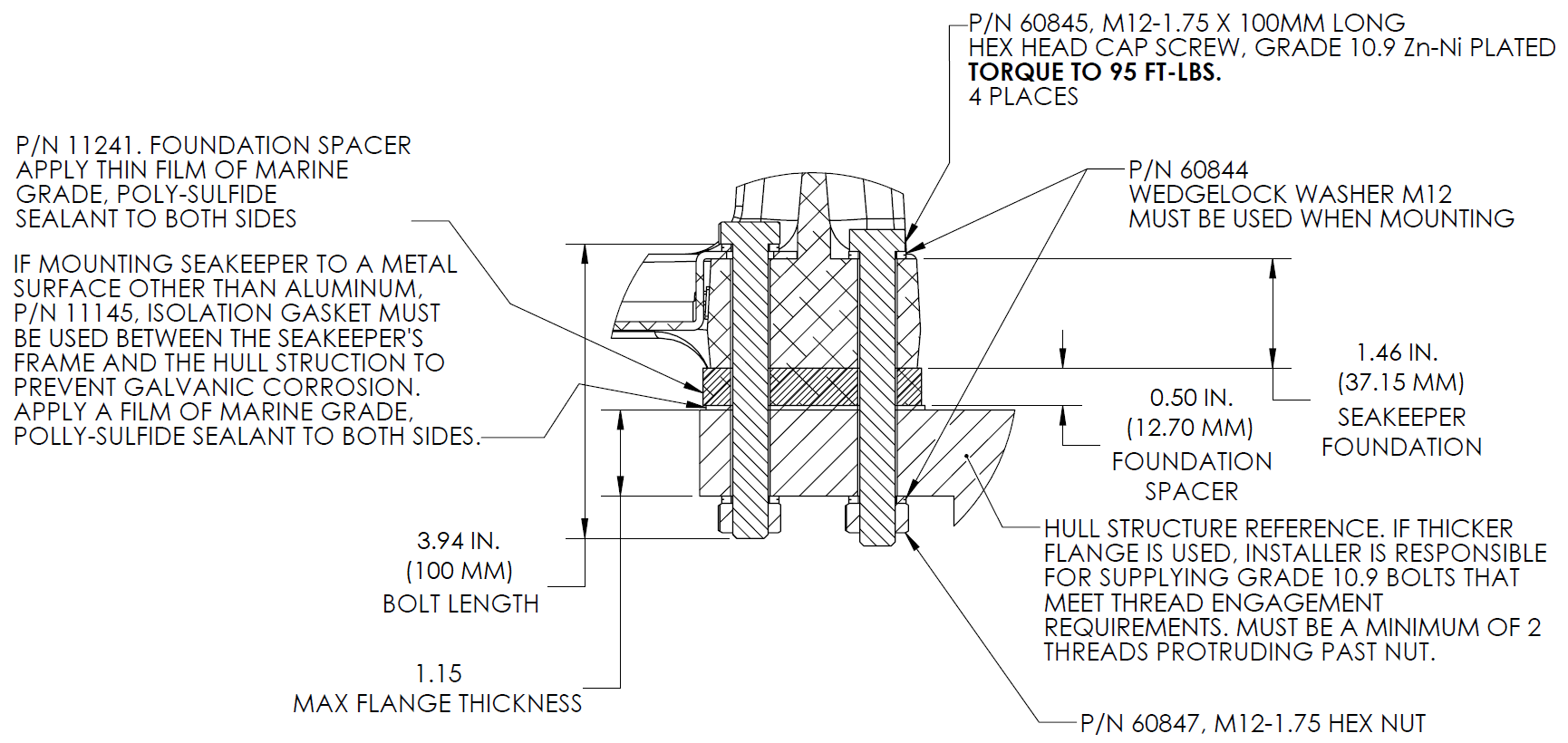
- For Through-Bolt installations (P/N 90660 – Seakeeper 6 / 5 Through-Bolt Kit), install the Seakeeper supplied M12-1.75 fasteners to maintain a minimum of 2 threads protruding past nut. Apply a moderate coat of nickel-based anti-seize (e.g., SAF-T-EZE nickel grade anti-seize, SBT-4N or equivalent) to the threads of each bolt and include a small bead of marine grade sealant (e.g., SILI-THANE 803 or equivalent) under each bolt head and washer before installation. See Figure 12.
- Torque all fasteners to 95 ft-lbs (129 N-m).
- New bolts, matching the Seakeeper specification, must be used for each installation and reinstallation that meet the requirements listed above.
- Proceed to electrical and cooling portion of the installation.