Seakeeper 2 Installation Manual (90488-4); S/N 2-232-1564 to Current
2.3.1 Preparation of Boat Structure
The Seakeeper Drawing No. 90590, Seakeeper 2 Generic Installation Guide shows various structural arrangements to support the installation of the Seakeeper. The Generic Installation Guide offers above and below deck installation arrangements with fiber-reinforced plastic (FRP) and aluminum structures, which should provide solutions for most vessels. The Seakeeper 2 is affixed to the hull structure via four bolts in the
Seakeeper 2 frame. Depending on the structure to which the Seakeeper is fastened, blind threaded holes or through-bolting can be utilized.
Refer to Seakeeper Drawing No. 90487, Seakeeper 2 Bolt in Installation Details. Important dimensional and load information is given in this drawing that will impact the design details of the structure that will receive the Seakeeper. It is assumed that a proper structural analysis has been performed for the hull structure to which the Seakeeper will be fastened to ensure proper strength margins for the loads the Seakeeper will create during operation.
The hull structure supporting the Seakeeper should be installed so the Seakeeper is parallel to the waterline in the transverse direction and within 1 degree longitudinally.
In addition, the four areas on top of the structure on which the Seakeeper 2 frame and isolation gaskets will rest, need to be co-planar within .06 in. (1.5 mm) to minimize potential distortion of Seakeeper support frame when installed. The isolation gaskets are only used when the Seakeeper 2 is mounted to a dissimilar metal structure.
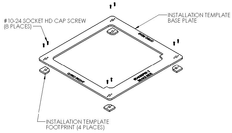
Seakeeper offers an optional installation template kit, P/N 90473, which contains four plates that mimic the mating surfaces of the four feet located on the Seakeeper ’s foundation. These plates have 4 holes located at the same centers as the mounting holes on the Seakeeper 3.The fixture locates the hole patterns at the proper spacing both in the forward-aft direction and the port-starboard direction. See Figure 4 below. Once assembled, the fixture can be used to check clearances and alignment of the hull structure.
Note: Do NOT use the installation fixture to establish the Seakeeper envelope dimensions. Refer to Drawing No. 90487 – Seakeeper 2 Bolt-In Installation Details, for envelope dimensions. A 3-D model of the Seakeeper is available on the Seakeeper Dealer Access website (www.seakeeper.com) to aid in designing the Seakeeper foundation and the space around the Seakeeper
NOTE: MAKE SURE NO OBSTRUCTIONS FROM THE HULL STRUCTURE CAN BE SEEN WITHINTHE INSIDE OF THE INSTALLATION TEMPLATE KIT (INSIDE THE MARKED RED LINES) AS SEEN IN FIGURE 5. REFERENCE SEAKEEPER DRAWING NO. 90487 – SEAKEEPER 2 BOLT-ININSTALLATION DETAILS
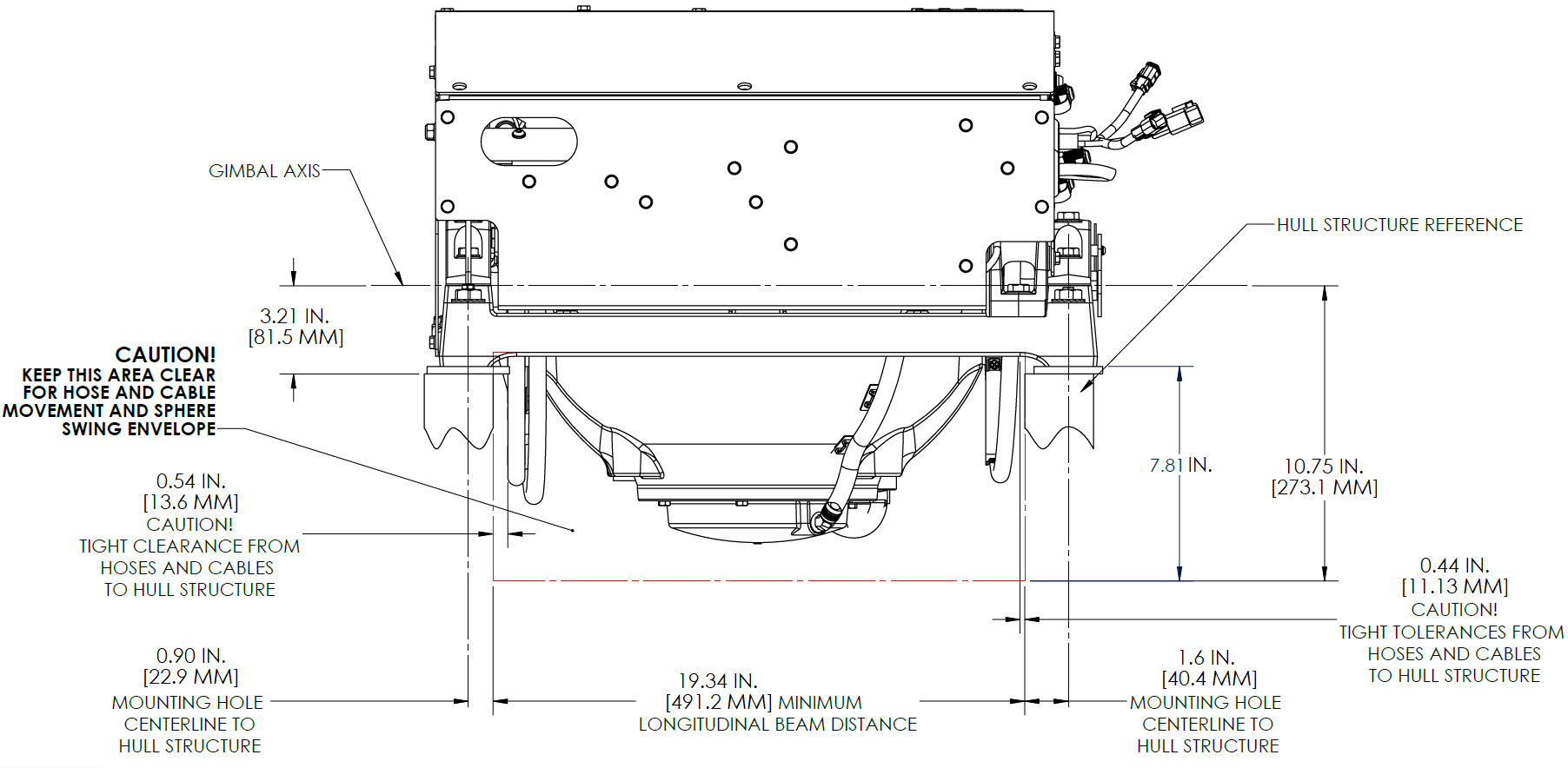
CAUTION: Tight clearances from cable guide bands to hull structure. See above Figure 5 for dimensions and reference Seakeeper Drawing No. 90487 – Seakeeper 2 Bolt-In Installation Details, for complete Seakeeper 2 envelope.