Seakeeper 2 Installation Manual (90488-4); S/N 2-232-1564 to Current
3.2.1 High Current 12 V Power Input
High Current 12 VDC Power Source Requirements
| Source | Battery Bank, 12 VDC, Marine, Deep Cycle (AGM battered recommended) |
| Voltage Range | 10 – 15 VDC |
| Continuous Current | 75 A |
| Overcurrent Protection | 100 A (Customer Supplied) |
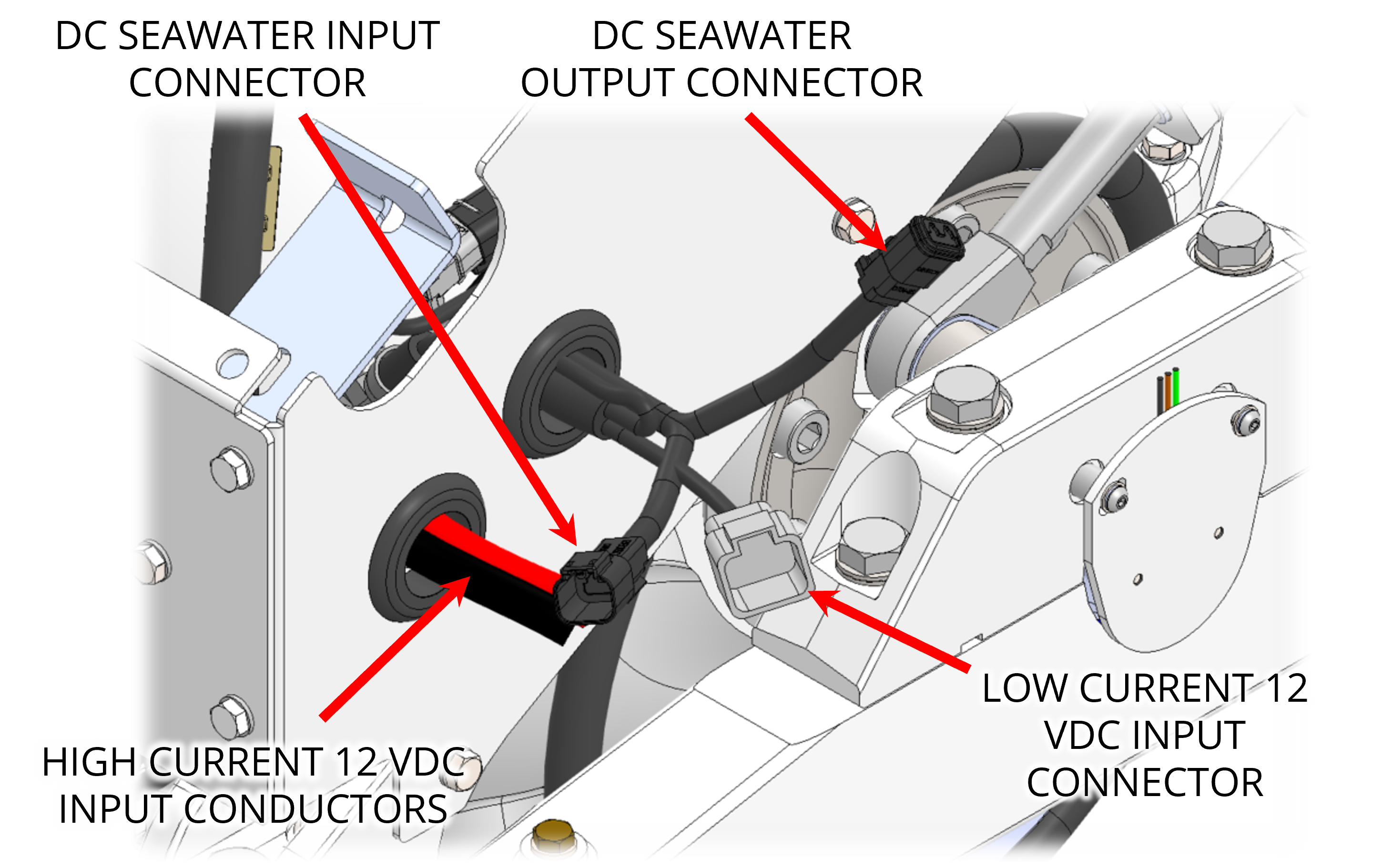
High Current 12 VDC Power Connection Instructions
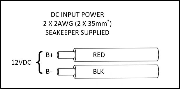
- High Current 2 AWG conductors connect the Seakeeper to the DC source are supplied as length 13ft (4 m). Approximately 3 ft (1 m) is routed inside the Seakeeper frame.
- If installing cables NOT provided by Seakeeper, ensure the folowing:
- Cable lengths do not exceed 29.5 ft (9 m)
- Cable gauge is 2 AWG or larger
- Cables bound together but not coiled
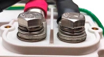
- When connecting aftermarket cables to the Seakeeper motor drive, observe the following:
- Ensure terminal stacks include flat washers, split-lock washers, and hex head screws that came with the Seakeeper.
- Torque battery terminal screws to 97 in-lbs (11 Nm).
- Verify lock washers seated flat and lugs cannot rotate (See Figure 12A).
- If installing cables NOT provided by Seakeeper, ensure the folowing:
- Conductor length may be increased, but changing from 2 AWG to larger wire size does not allow longer length than 30 ft (9 m) each. The length limit is required to limit the inductance from the high current conductors.
- Use the shortest length and most direct route to the battery bank as possible.
- Bind positive (B+, red) & negative (B-, black) conductors together throughout entire length and do not coil.
- Connect positive conductor (B+, red) through dedicated over-current protection device (customer supplied) and a dedicated isolation switch (customer supplied) then directly to battery positive terminal.
- Connect negative conductor (B-, black) directly to battery negative terminal.
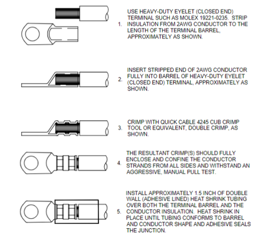
- If the 2 AWG high current 12 V power input conductors are shortened or lengthened, use heavy-duty eyelet (closed end) terminal such as Molex 19221-0235 and follow instructions on Seakeeper Drawing No. 90470 – Seakeeper 2 Cable Block Diagram, sheet 2.
- The bare wire strands should extend fully into the barrel of the heavy-duty eyelet and be crimped in two places if possible then sealed with double-wall heat shrink tubing. Crimp heavy-duty terminals with Quick Cable 4245 Crimp Tool, Molex 19284-0034 Crimp Tool, or equivalent using manufacturer’s instructions.