Seakeeper 2 Installation Manual (90488-4); S/N 2-232-1564 to Current
2.0 Mechanical Installation
2.1 Mechanical Installation Introduction
The Seakeeper 2 is capable of producing loads up to 1,459 lbs (6.49 kN) at each of the four mounts and careful consideration should be given to foundation design to insure it is capable of transferring these loads into the hull. These loads do NOT include vessel motion accelerations, such as vertical slam loads which can be high for higher speed vessels. Seakeeper suggests a safety factor of 3.0 (yielding a safety margin of 2.0).
There are two methods of installing the Seakeeper 2:
1. Longitudinal Bolt-In Installation
2. Transverse Bolt-In Installation
It is assumed that the installer is familiar with mounting using mechanical fasteners to marine structures and has performed structural analysis to assure the structure to which the Seakeeper mounts can properly transfer the loads the Seakeeper creates into the hull structure. If the installer has any doubt about the ability of the structure to transfer the loads to the hull then the installer should contact a licensed naval architect or marine engineer to do a structural analysis.
The installer should review the following list of reference drawings to ensure the installation procedure is fully understood.
Reference Documents & Drawings:
- 90469 – Seakeeper 2 Hardware Scope of Supply
- 90487 – Seakeeper 2 Bolt-In Installation Details
- 90492 – Seakeeper 2 Bolt-In Clearances
- 90473 – Seakeeper 2 Installation Template Kit
- 90474 – Seakeeper 2 Blind-Hole Kit (Standard)
- 90590 – Seakeeper 2 Generic Installation Guide
- 90636 – Seakeeper 2 Thru-Bolt Kit (Optional)
2.2 Selection of Installation Location
Selection of mounting location of the Seakeeper should consider the following desirable features:
The Seakeeper should be installed aft of amidships to minimize high acceleration loadings due to hull/wave impacts during operation at high speed or in large waves. If the only possible Seakeeper location is forward of amidships then the installer should have Seakeeper review the installation location prior to finalizing the design.
- Top down access or sufficient clearance for removal / re-installation of the Seakeeper for overhaul in future years.
- The Seakeeper should be installed in a dry space to minimize effects of corrosion.
- Clearance for all recommended scheduled maintenance and any repairs that may be necessary (see Figure 2).
VIEWS SHOWING RECOMMENDED CLEARANCES AROUND THE SEAKEEPER FOR USE OF HANDTOOLS, EASE OF MAINTENANCE, INSTALLATION, AND PROPER OPERATION.
Figure 2 – Seakeeper 2 Installed Clearance Considerations
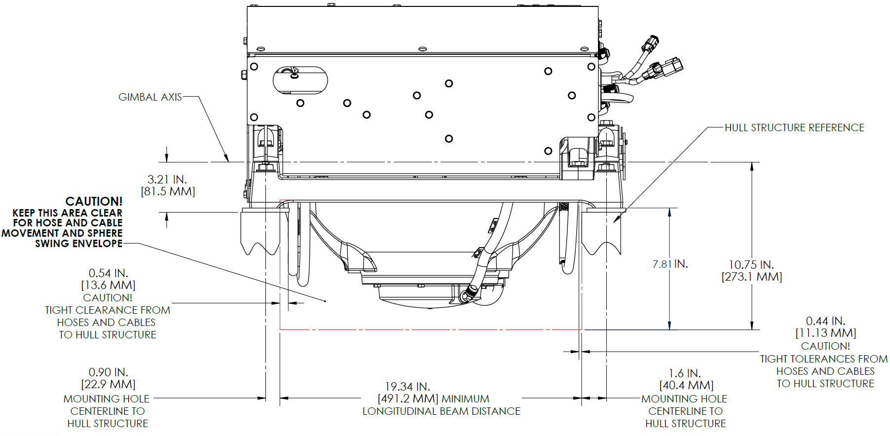
Refer to Figure 3 for recommended clearances to transverse or longitudinal beams. Clearances aft of the Seakeeper are shown to provide access for regular scheduled maintenance.
Noise/Soundproofing
Seakeeper noise has been measured under steady state conditions (no wave load) in Seakeeper‘s Engineering Lab and in our Factory Demo Boat. The steady state noise at 1 meter is typically less than 68 dBC. As the frequencies emitting the highest sound pressures are low (like other marine machinery), it is recommended that the Seakeeper be installed in a machinery space that is already treated with soundproofing.
2.3 Bolt-In Installation
2.3.1 Preparation of Boat Structure
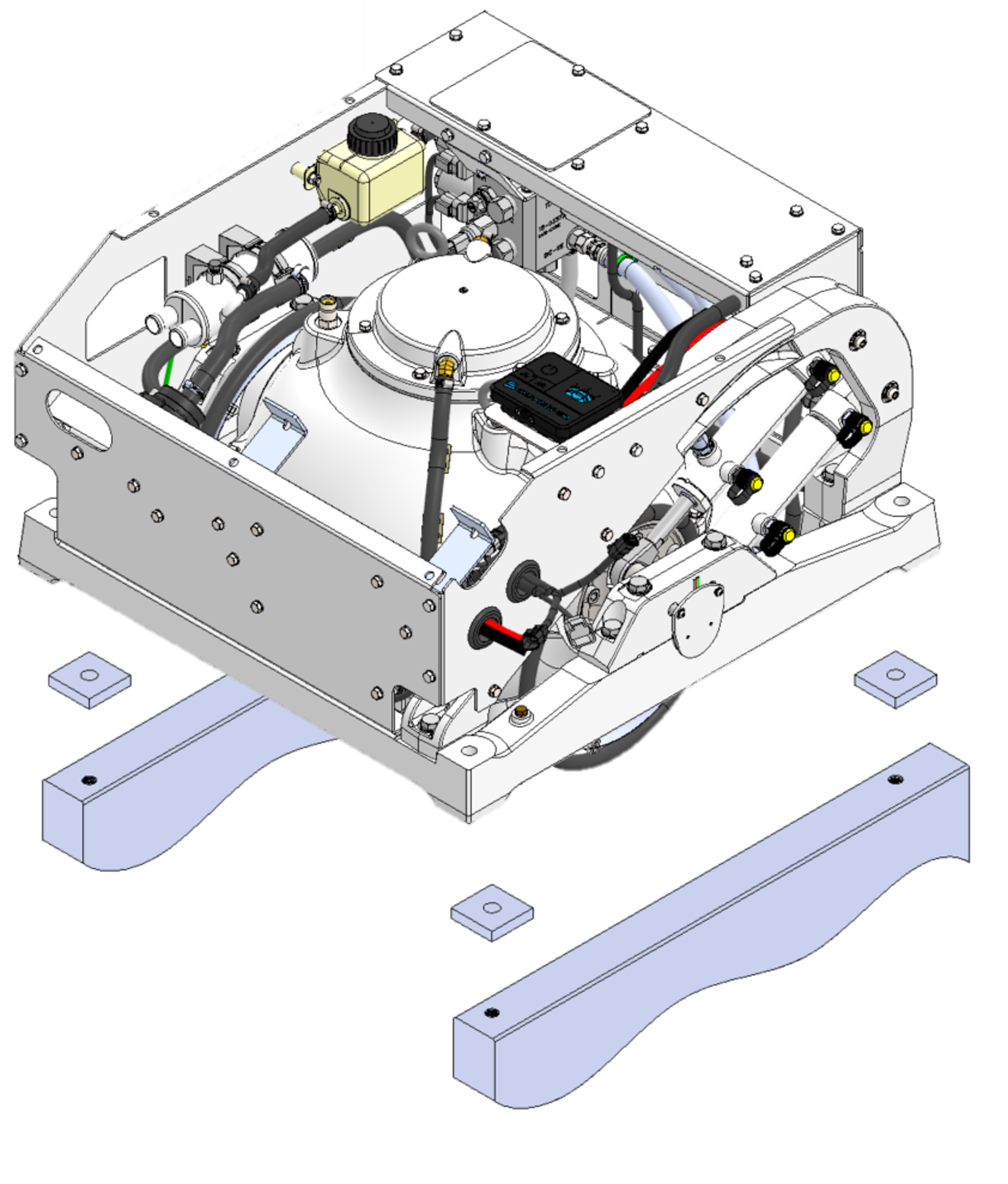
The Seakeeper Drawing No. 90590, Seakeeper 2 Generic Installation Guide shows various structural arrangements to support the installation of the Seakeeper. The Generic Installation Guide offers above and below deck installation arrangements with fiber-reinforced plastic (FRP) and aluminum structures, which should provide solutions for most vessels. The Seakeeper 2 is affixed to the hull structure via four bolts in the
Seakeeper 2 frame. Depending on the structure to which the Seakeeper is fastened, blind threaded holes or through-bolting can be utilized.
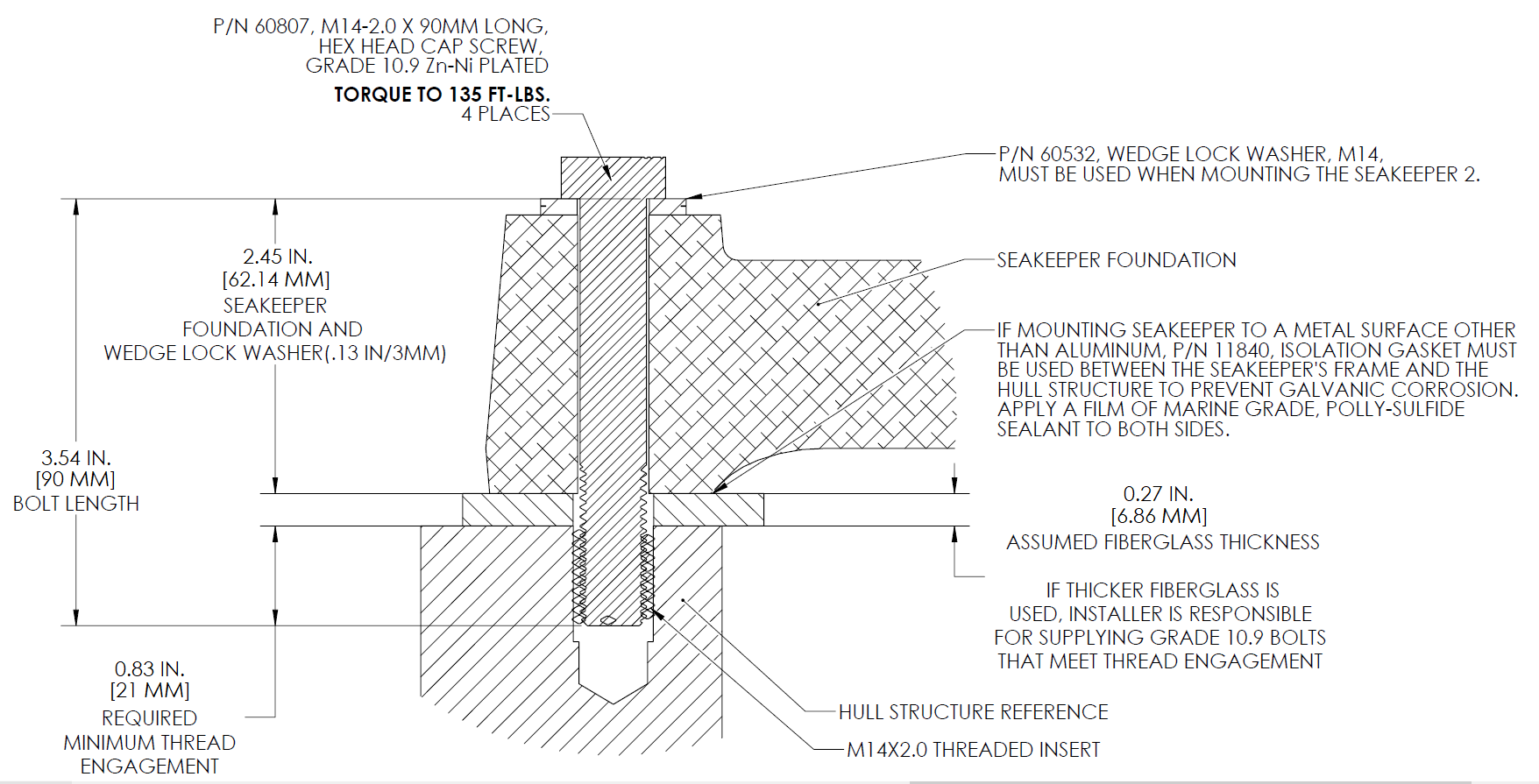
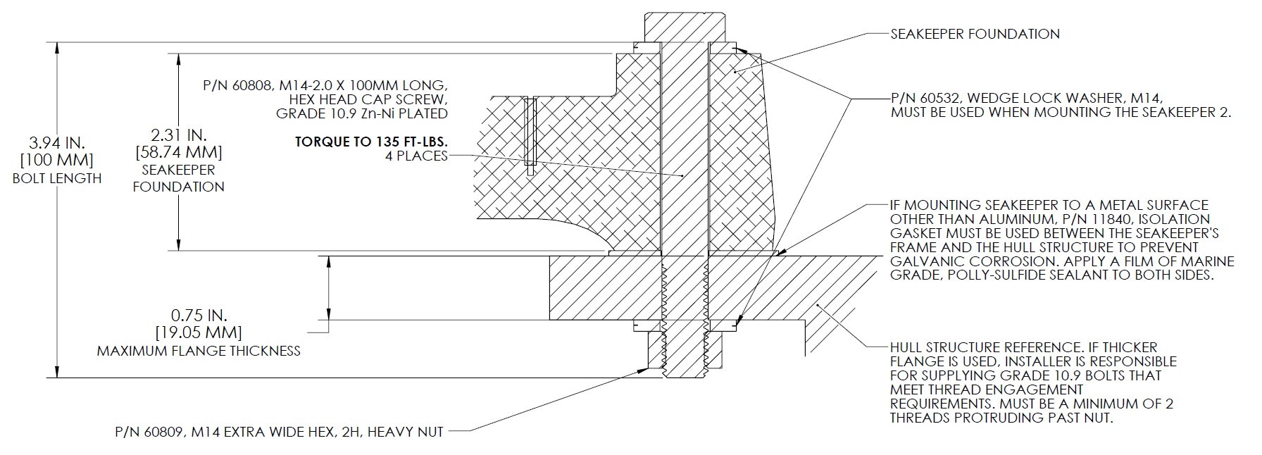
Refer to Seakeeper Drawing No. 90487, Seakeeper 2 Bolt in Installation Details. Important dimensional and load information is given in this drawing that will impact the design details of the structure that will receive the Seakeeper. It is assumed that a proper structural analysis has been performed for the hull structure to which the Seakeeper will be fastened to ensure proper strength margins for the loads the Seakeeper will create during operation.
The hull structure supporting the Seakeeper should be installed so the Seakeeper is parallel to the waterline in the transverse direction and within 1 degree longitudinally.
In addition, the four areas on top of the structure on which the Seakeeper 2 frame and isolation gaskets will rest, need to be co-planar within .06 in. (1.5 mm) to minimize potential distortion of Seakeeper support frame when installed. The isolation gaskets are only used when the Seakeeper 2 is mounted to a dissimilar metal structure.
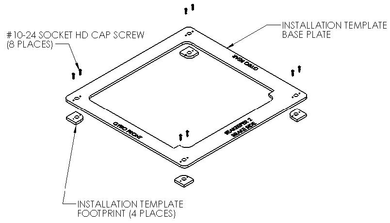
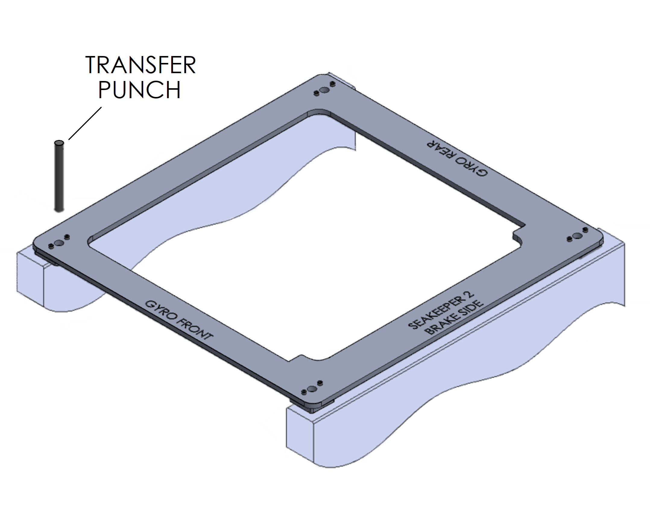
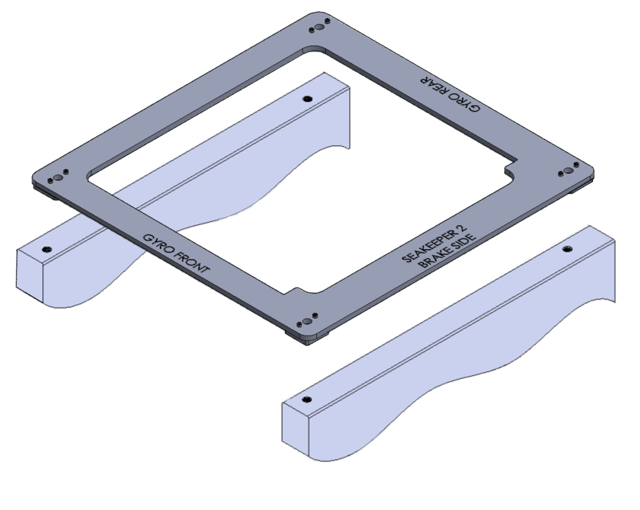
Seakeeper offers an optional installation template kit, P/N 90473, which contains four plates that mimic the mating surfaces of the four feet located on the Seakeeper ’s foundation. These plates have 4 holes located at the same centers as the mounting holes on the Seakeeper 3.The fixture locates the hole patterns at the proper spacing both in the forward-aft direction and the port-starboard direction. See Figure 4 below. Once assembled, the fixture can be used to check clearances and alignment of the hull structure.
Note: Do NOT use the installation fixture to establish the Seakeeper envelope dimensions. Refer to Drawing No. 90487 – Seakeeper 2 Bolt-In Installation Details, for envelope dimensions. A 3-D model of the Seakeeper is available on the Seakeeper Dealer Access website (www.seakeeper.com) to aid in designing the Seakeeper foundation and the space around the Seakeeper
NOTE: MAKE SURE NO OBSTRUCTIONS FROM THE HULL STRUCTURE CAN BE SEEN WITHINTHE INSIDE OF THE INSTALLATION TEMPLATE KIT (INSIDE THE MARKED RED LINES) AS SEEN IN FIGURE 5. REFERENCE SEAKEEPER DRAWING NO. 90487 – SEAKEEPER 2 BOLT-ININSTALLATION DETAILS
CAUTION: Tight clearances from cable guide bands to hull structure. See above Figure 5 for dimensions and reference Seakeeper Drawing No. 90487 – Seakeeper 2 Bolt-In Installation Details, for complete Seakeeper 2 envelope.
2.3.2 Transfer of Holes to Boat Structure
- Lower assembled fixture onto hull structure.
- The four areas where the feet of the Seakeeper will rest should be coplanar to within .06 in. (1.5 mm). See Figure 6.
- Align fixture in desired location and transfer holes from fixture plate to the hull structure using provided transfer punch. Note that holes in fixture plate are ø0.60 in. (15.138 mm).
- Remove fixture and drill and tap M14X2.0 Helicoil threaded insert holes in hull structure at marked locations to mate with holes in the Seakeeper foundation. Take special care to drill perpendicular to mounting surface. A drill guide is recommended. Remove any impeding obstructions.
2.3.3 Installation of Seakeeper
- Lower Seakeeper into position onto the hull foundation beams and align over drilled holes. Apply a small bead of marine sealant (e.g., SILI-THANE 803 or equivalent)between mating surfaces of Seakeeper frame and hull structure to prevent moisture wicking into bolt holes.
- For dissimilar metal foundations locate and position 4 isolation gaskets onto foundation beams and apply a small bead of marine sealant (e.g., SILI-THANE 803or equivalent) between both mating surfaces of each isolation gasket where it contacts the beam and the Seakeeper (See Figure 7).
- Install mounting bolts:
- For Blind Hole Installations, install the Seakeeper supplied Grade 10.9, M14-2.0 x90 mm fasteners or alternative Grade 10.9, M14-2.0 bolts to maintain a minimum thread engagement of 0.83 in (21 mm). If Seakeeper supplied bolts do not achieve the minimum thread engagement because of the lamination thickness or structure, longer bolts of the same specification (M14-2.0, Grade10.9) should be sourced. If tapping directly into a metal frame shorter bolts maybe required. Apply a moderate coat of marine anti-seize (e.g., SAF-T-EZE nickel grade anti-seize, SBT-4N or equivalent) to the threads of each bolt and include a small bead of marine grade sealant (e.g., SILI-THANE 803 or equivalent) under each bolt head and washer before installation. See Figure 8 below.
- For Through-Bolt installation install the Seakeeper optional Thru-Bolt Kit (P/N 90636) Grade 10.9, M14-2.0 x 100 mm fasteners with a minimum of 2 threads passing through the nut If Seakeeper supplied bolts do not pass entirely through the Extra Wide / Heavy Hex Nut because of the frame thickness, longer bolts of the same specification (M14-2.0, Grade 10.9) should be sourced. Apply a moderate coat of marine anti-seize (e.g., SAF-T-EZE nickel grade anti-seize, SBT-4Nor equivalent) to the threads of each bolt and include a small bead of marine grade sealant (e.g., SILI-THANE 803 or equivalent) under each bolt head and washer before installation. See Figure 9 below.