Electrical Installation Manual
8.3. Distribution Module Wiring
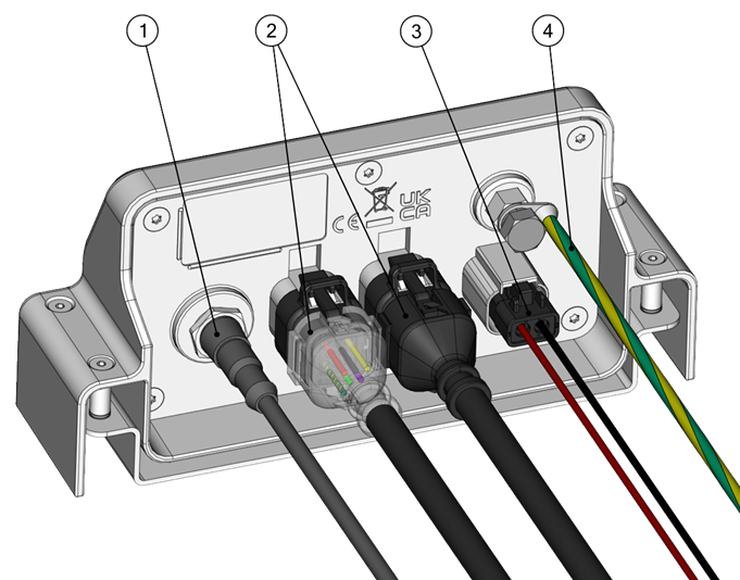
- Seakeeper CAN Bus
- Controller Cables
- Power Cable
- Ground Wire
Seakeeper Ride Proprietary CAN Bus Cable
Connect one end of the supplied NMEA 2000 Cable to the Distribution Module. Connect the other end of the NMEA 2000 Cable to the CAN Bus Tee (B in Figure 11). The supplied 0.6 m (2 ft) Cable is recommended. Ensure a Male Terminator (A in Figure 11) is installed at the this end of the CAN Bus Tee.
Controller Cables
The Controllers arrive with a custom cable appropriate for installation in the most challenging areas of a boat. The cables are resistant to water, oil, and electromagnetic interference.
Note: This cable is not to be modified. Do not allow acetone to come in contact with the Controller Cable Gland Sealing Nut (Figure 56 in the Mechanical Installation Manual)

ATTENTION: When inserting cable end pins into the Ampseal Plug, please use caution. Damage to these pins will result in Actuator replacement.
The cable ends must be inserted into the Ampseal plug. Slide shrink wrap over the wire prior to inserting cable ends. Ensure the wedge lock on the Ampseal Plug Housing is open. Follow Drawing No. 90609 – Seakeeper Ride Cable Block Diagram and Figure 14 for specific color to pin number identification. Review these written instructions, and this video from Ampseal for best practices. If ports 7 and 8 are accidentally pierced, be sure to insert Ampseal Cavity Sealing Plugs to prevent water from entering. Close the wedge lock by squeezing it firmly onto the Ampseal Plug Housing.
Once the pins are secured in the Ampseal plug, apply the heat shrink over the point where the cables meet the Ampseal plug. The plug is then ready to be attached to the Distribution Module. Do not connect the Controller Cables to the Distribution Module at this point. The cables will be connected during the commissioning procedure for proper programming and identification.
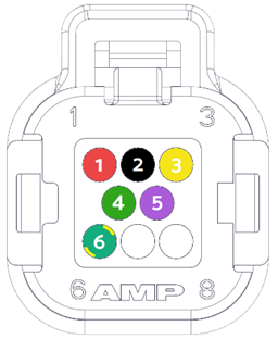
1. RED, +V (16 AWG)
2. BLACK, 0V (16 AWG)
3. YELLOW, CAN_HI (20 AWG)
4. GREEN, CAN-LO (20 AWG)
5. PURPLE, WAKE (20 AWG)
6. GREEN/YELLOW, GND (16 AWG)
(7 and 8 are left blank or have plugs if pierced.)

ATTENTION! The specific color to pin number identification is critical. Incorrect placement may result in destruction of the Actuator.
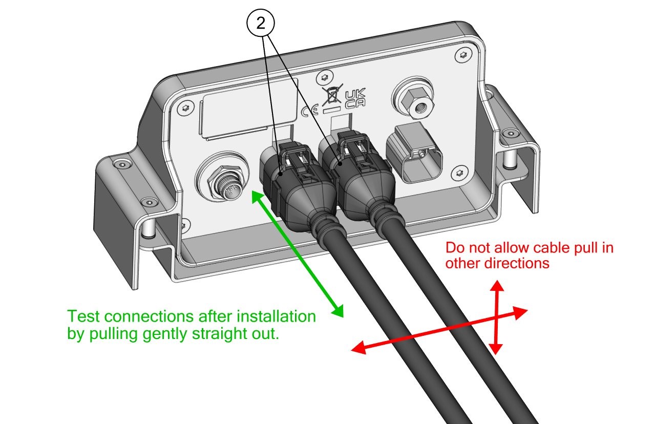
When connecting the Controller Cables during commissioning, test to make sure they are attached correctly. Controller Cables should click in and fit firmly once inserted. When Controller Cables are secured, gently pull straight out to ensure they do not come out. To ensure the cables remain properly attached, do not allow the cables to be pulled in any other direction at any time.
Ground Wire
The ground wire cable attaches the Distribution Module to the vessel’s common ground. Attach the loose eyelet of this cable to the common ground of the boat. The ground wire should be wired to bus bar going straight to the battery. Do not ground through another electrical system on the boat.
This cable must be 8 AWG or larger.

WARNING! Do not squeeze or crimp the cables too tightly or they could fail.
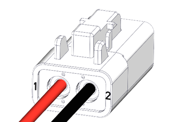
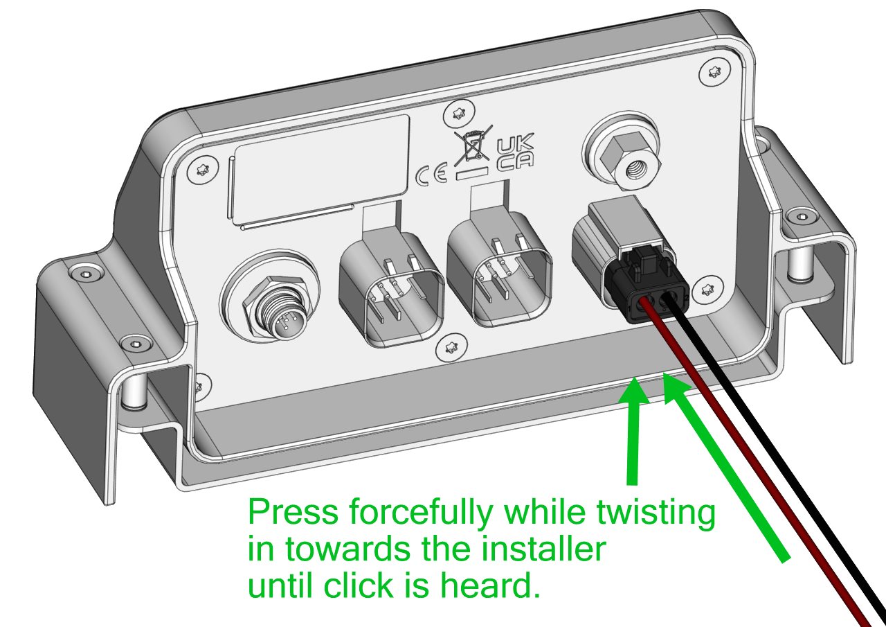
Power Cable
The power cable provides power to the Distribution Module so the Controllers can move as needed. The power cable is made up of two (2) 12 AWG wires, one red and one black.
The black wire is to be attached to the negative terminal of the vessel’s 12 V power, and the red wire is to be attached to a 25 A circuit breaker or fuse. The power to the circuit breaker or fuse is to be supplied by the vessel’s battery isolation switch and the positive side of 12 V power.
WARNING! Do not reverse the polarity of the Power Cable. INCORRECT WIRING, SUCH AS THIS, MAY RESULT IN DESTRUCTION OF EQUIPMENT, DAMAGE TO THE BOAT OR OTHER PROPERTY, SERIOUS INJURY OR DEATH.
When connecting the power cable into the Distribution Module, press in forcefully while twisting in towards the installer until a small, audible clicking sound is heard. When the power cable is secured, gently pull straight out to ensure it does not come out.
If the Power Cable is not used, choose a power cable that has at least 12 AWG wires to ensure sufficient power supply to the Actuators. Do not use a power cable longer than 10 m (32.8 ft), as the equipment is voltage-sensitive and current-sensitive. The power cable termination must be in a 2-pin Deutsch plug Part Number DTP06-2S with the red wire in terminal 1 and the black wire in terminal 2 as shown below. Review this video from Deutsch for best practices.