Electrical Installation Manual
6. Component Details and Installation Location
Component Details and Installation Location Introduction
Selecting a proper location for the Software Module is critical to the successful and safe function of the system. Selection of mounting location on the boat should adhere to the guidelines in this section.
6.1. Software Module
The Software Module must be mounted on a structurally sound vertical surface. Vibration or shaking of this mounting surface is unacceptable and may cause the system to malfunction.
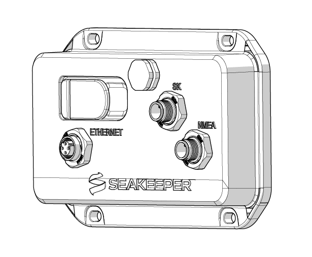
A minimum of 5 in. (12.7 cm) of clearance is required on the cable connection side the Software Module to allow for proper installation of cables.
The Software Module needs to be level to both port/starboard and bow/stern. The Software Module can accept up to 15 degrees of offset in both planes. Due to the Software Module being responsible for measuring the roll, pitch, and yaw of the vessel, leveling is imperative for maximum performance of the Seakeeper Ride system.
When checking the level of the unit during installation, it is best to have the boat level port/starboard and the forward/aft trim equal to the boat’s waterline when at rest. This can be accomplished on a trailer, on jack stands, lifts, or floating in calm water.
 IMPORTANT: Since the Software Module contains the motion sensor, IT MUST be mounted with the Seakeeper logo upright and facing either forward or aft (the logo CAN NOT be facing either side of the boat). Mount the Software Module as close to the operator as possible.
The Software Module should be readily accessible for software updates.
Warning: The stabilization system in the Software Module relies on fine movements and vibrations in the boat to provide unprecedented stability control. Speakers are of great concern due to the vibrations induced on the mounting surfaces.
6.2. Distribution Module
The Distribution Module provides power and communication to the Seakeeper Ride Controllers mounted to the transom. The Distribution Module should be installed on a structurally sound vertical surface, mounted with the Seakeeper logo upright.
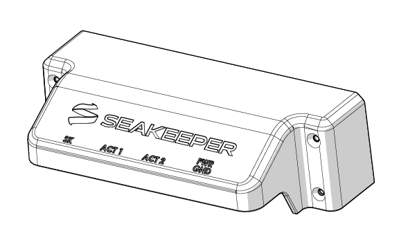
A minimum of 5 in. (12.7 cm) of clearance is required beneath the Distribution Module to allow for proper installation of cables.
The Distribution Module must be mounted close to both Controllers, as the Actuator Cables are 10 feet (3.0 meters) long. To accommodate the cable length, the Distribution Module should be mounted in the stern of the boat as high as practical to minimize exposure to bilge water.
Note: Actuator Cables cannot be extended due to power loss restrictions.
6.3. Keypad (Optional)
The optional Keypad sold separately is designed to be installed at the helm for the vessel operator to make manuals trim and list adjustments.
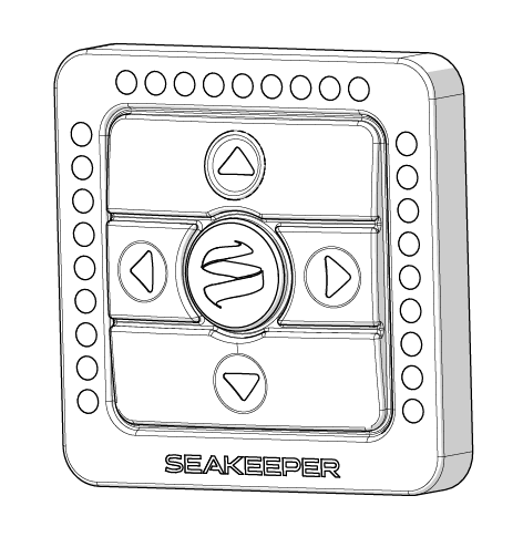
Select a location on the dashboard for the Keypad. Overall Dimensions of the keypad are 2.65 in X 2.65 in (67.3 mm X 67.3 mm).
The Keypad provides functionality when the system is in Auto and Manual modes. When the system is in Manual mode, it behaves as a static list/trim control system. Please refer to the Operation Manual and/or the Quick Start Guide for more information on using the Keypad.
6.4. Seakeeper Ride Proprietary CAN Bus
Seakeeper Ride uses a unique signal to communicate between the components in the system. Though NMEA 2000 cables and connectors are used, the Seakeeper Ride Proprietary CAN Bus must be separate from the boat’s Navigation NMEA 2000 backbone. Be sure to distinguish the two CAN Bus networks when performing the electrical installation.
Ensure the Seakeeper Ride Proprietary CAN Bus is readily accessible for maintenance and service, near the Software Module.
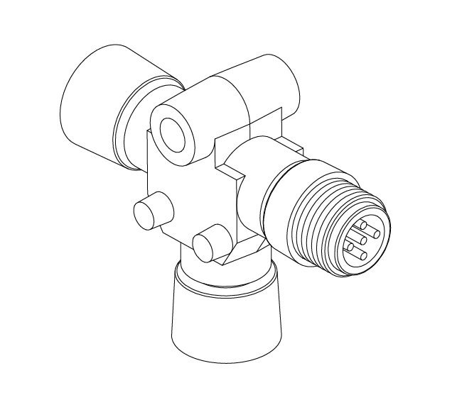
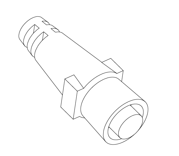
Figure 6 – NMEA Tee and Terminator
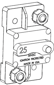
6.5. 25 Amp Circuit Breaker or Fuse
For protection of the Seakeeper Ride system and general safety, the positive end of the Distribution Module’s Power Cable must be wired to a 25 Amp Circuit Breaker or fuse, which is not included. The Circuit Breaker or fuse should be readily accessible. We recommend mounting this close to the Software Module for quick inspection and power cycling when necessary.

FAILURE TO UTILIZE A 25 AMP CIRCUIT BREAKER OR FUSE COULD CREATE A FIRE RISK.