Electrical Installation Manual
7. Mounting
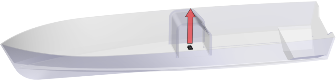
7.1. Software Module Mounting
- Trace Mounting Holes. Based on the selection criteria (Section 6.1) for mounting location, hold the Software Module in the designated location. Using a writing utensil, mark the location of the four (4) mounting holes located in each corner.
- Drill Holes. Prior to drilling the pilot holes, confirm that the mounting surface is greater than 1 in. (25.4 mm) thick. Once the depth has been confirmed, drill pilot holes for each of the four (4) positioning screws using a 1/8 in. drill bit approximately 3/4 in. (15.9 mm) deep.
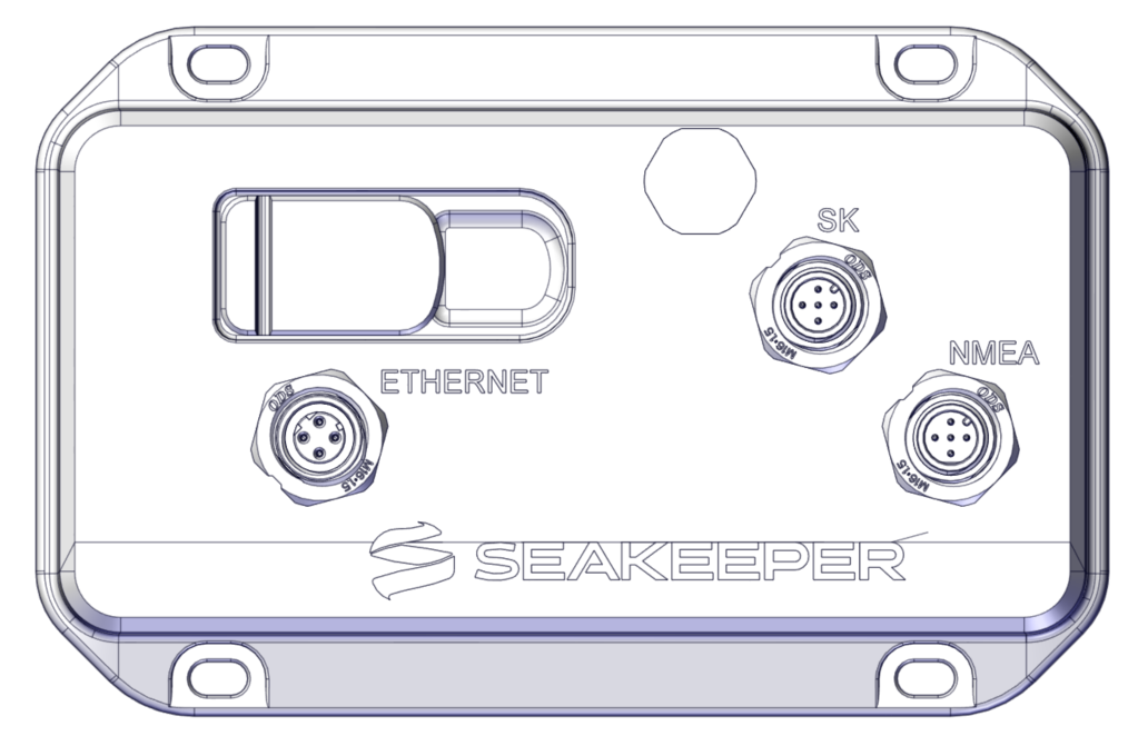
- Insert Screws. Hold the Software Module in place and using a screwdriver, install the four (4) Phillips No. 10 x 1 in. screws. Ensure the Seakeeper logo is upright, and mounting is secured.
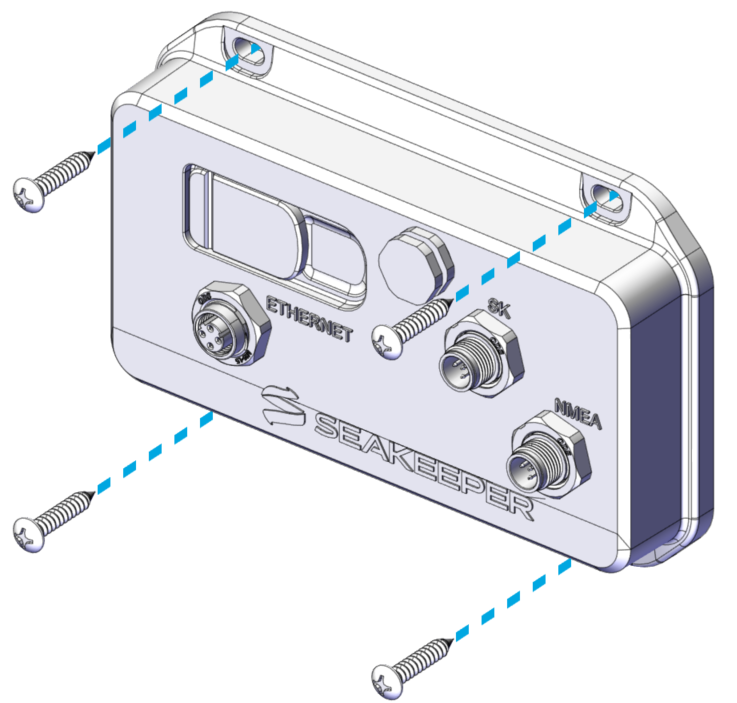
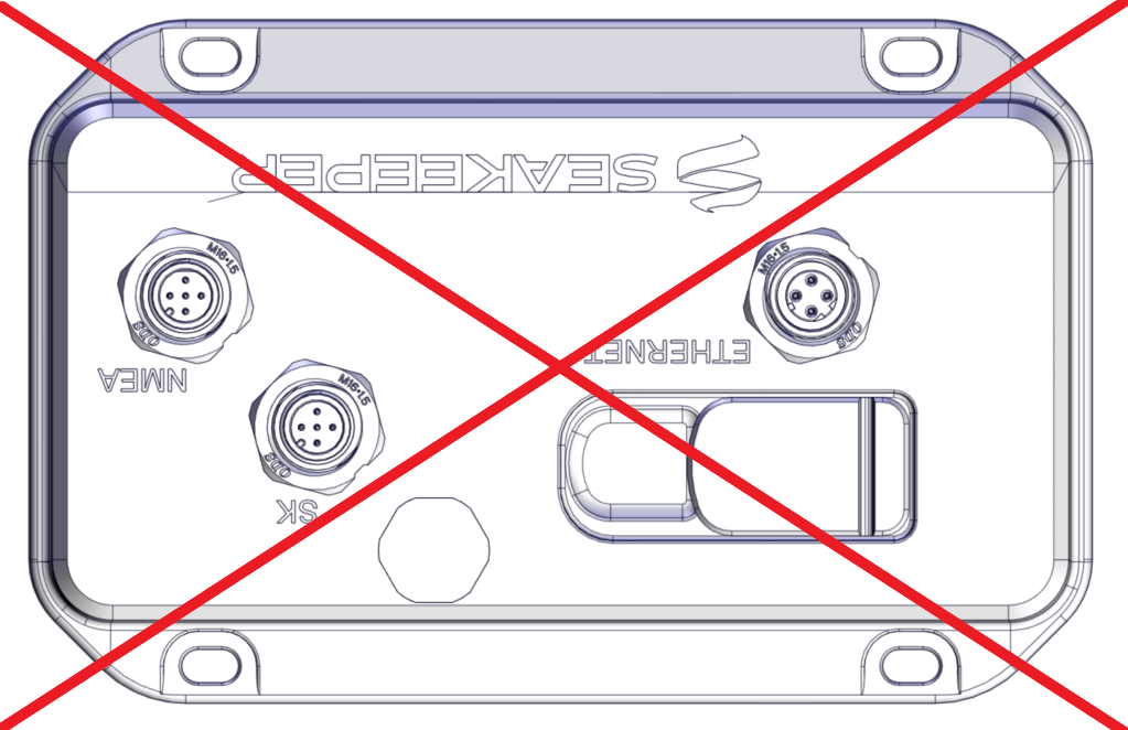
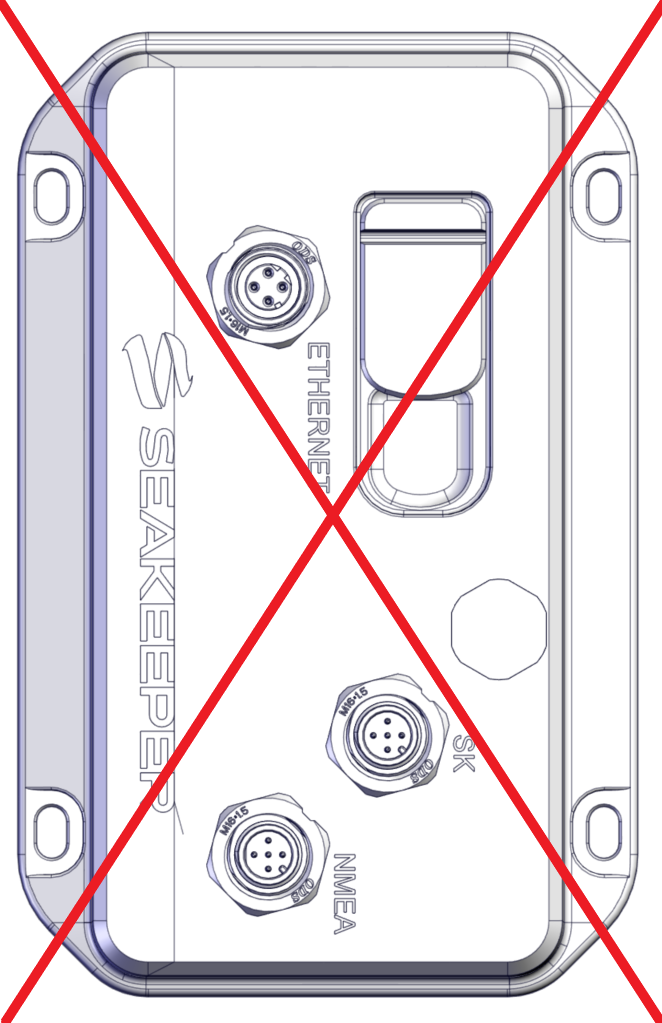
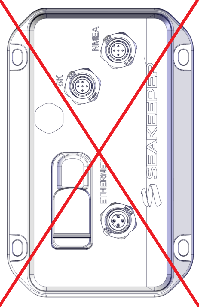
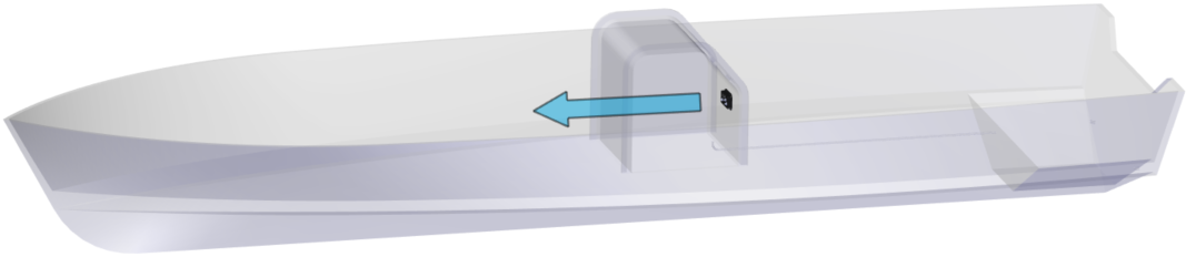
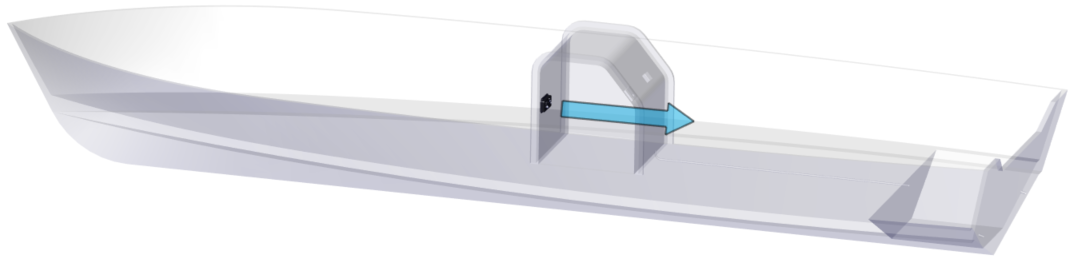
 IMPORTANT: The Software Module MUST be mounted with the Seakeeper logo upright and facing either forward or aft (the logo CAN NOT be facing either side of the boat). The Software Module CAN NOT be mounted on the floor. Mount the Software Module as close to the operator as possible.

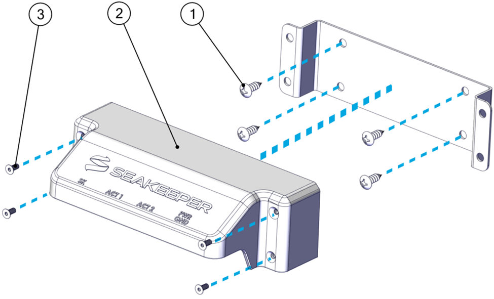
7.2. Distribution Module Mounting
- Trace Mounting Holes. Based on the selection criteria for mounting location (Section 6.2), hold the Distribution Module Mounting Bracket in place. Mark the location of the four (4) inner mounting holes using a writing utensil.
- Drill Holes. Prior to drilling the pilot holes, confirm that the mounting surface is greater than 3/4 in. (19 mm) thick. Once the depth has been confirmed, drill pilot holes for each of the four (4) positioning screws using a 1/8 in. drill bit approximately 5/8 in. (19 mm) deep.
- Insert Screws. Hold the Distribution Module bracket in place. Using a screwdriver, install the four (4) Phillips No. 12 x 0.75 in. mounting screws.
- Mount Distribution Module. Once the bracket is in place, slip the Distribution Module on top of the Mounting Bracket. Use the four (4) M4 x 10 mm flat head socket cap screws to install the Distribution Module onto the bracket with a 2.5 mm hex key and tighten.
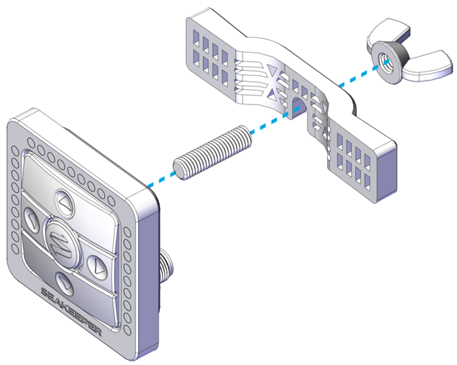
7.3. Keypad Mounting (Optional)
Note: The Keypad is not necessary for the operation of Seakeeper Ride. All Keypad controls can be found on the MFD application. Prior to cutting and drilling, ensure no objects are behind the surface that you do not intend to cut during the procedure.
- Trace Mounting Holes. Find and print the full-scale template of the Keypad to assist with tracing HERE, verifying the printed size is correct (the square is 2.25 in. X 2.25 in. [57.2 mm X 57.2 mm]). Tape the template in the desired mounting location. This will be used to create the square cutout for the Keypad to be inserted into.
- Drill Holes. Drill 1/4 in. holes through the mounting surface in each corner of the square. Hole locations are shown on the template by the circles in the corners.
- Cut Lines. Using a jigsaw or oscillating tool, cut along the remaining perimeter of the solid square.
- Mount Keypad. Thread the provided stud onto the Keypad. Screw the M8 Wing Nut onto the stud, leaving room to accommodate the Mounting Bracket between the Keypad and Wing Nut. Align the Keypad so the Logo is at the bottom, facing the vessel operator. Slide the Keypad Mounting Bracket onto the stud between the Wing Nut and the Keypad. Tighten the Wing Nut to hold the bracket in place.