Electrical Installation Manual
Seakeeper Ride | Electrical Installation Manual
1. Introduction
Updated 03/21/2024
This document is intended to give details and guidance to a boat builder or equipment installer on the proper procedure for the electrical installation of a Seakeeper Ride system.
Because of the quantity of parts and careful installation requirements, set aside a clean, well-ventilated workspace, take inventory of necessary tools and parts, and review the entirety of this manual before setting to work.
Note: Scan the QR code below to access Seakeeper Ride BILT 3D instructions.

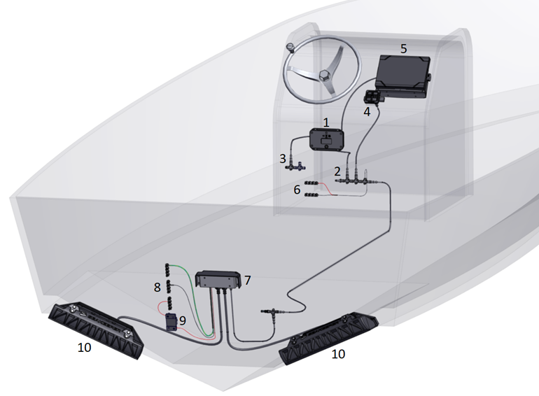
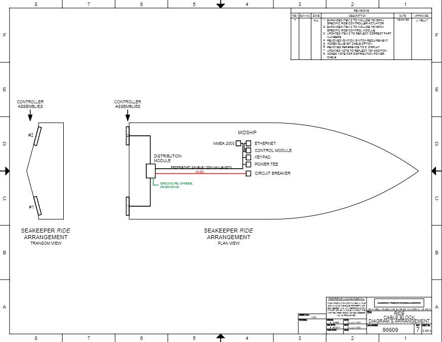
*Blue highlighted = Seakeeper Ride
*Gray highlighted = Boat’s own supply
1. Software Module
2. Seakeeper Ride Proprietary CAN Bus
3. NMEA 2000 Backbone
4. Keypad (Optional)
5. Multifunction Display (MFD)
6. Positive and Negative Power Terminals
7. Distribution Module
8. Positive, Negative, and Ground Terminals
9. 25 Amp Circuit Breaker Controllers or Fuse
10. Controllers
2. Safety Notices
2.1. Stability
This system is not intended, nor should it be expected, to provide underway dynamic stability beyond the limits of the hull itself. It is up to the captain of the vessel to ensure that the hull is kept and operated in a safe manner, within the limits defined by the manufacturer.
2.2. Electrical Hazards
Please ensure all electrical systems on the boat are turned off before beginning this procedure. This includes battery switches, engines, generators, shore power connections, and navigation electronics. Improper connections may cause unintended power, groundings, or shock to installation personnel or Seakeeper Ride components.
Marine electronics pose a hazard to those handling them. Please use caution and respect the potential for injury due to electrical hazards inherent in systems with batteries, engines, and alternators.
2.3. Installation Personnel
It is imperative that the installer is ABYC certified and/or familiar with electrical installations in marine applications. Utilizing marine grade equipment, connections and materials will help ensure proper operation.
If the installer has any doubt about the integration of Seakeeper Ride with the boat’s navigation and propulsion equipment, they should contact the manufacturer for guidance.
The installer must review the following list of reference drawings before beginning the installation procedure.
FAILURE TO FOLLOW THESE INSTRUCTIONS MAY LEAD TO PERSONAL INJURY OR FAILURE OF THE SEAKEEPER RIDE SYSTEM TO OPERATE AS INTENDED.
2.4. Installation Materials
Seakeeper supplies quality cables and terminals to ensure long-lasting and consistent operation of the electrical system. Substituting cables, terminals, and other components from the Seakeeper-supplied equipment may affect the system’s operation and could void the warranty.
Adhesive-lined heat shrink is highly recommended for long life and durability on components that need to be terminated by the installer.
Please use the highest quality NMEA 2000 CAN bus cables, Tees, and power drops when necessary. CAN bus cables are critical to the operation of the system and poor-quality cables and connectors can inhibit or stop operation of the Seakeeper Ride system.
Securing materials should be used to hold cables in place according to ABYC standards.
2.5. Installation Tools
Proper electrical tools should be used for all aspects of electrical installation to avoid destruction of cables and terminals. Avoid the use of open flames to apply heat to heat shrink materials to avoid damaging cables.
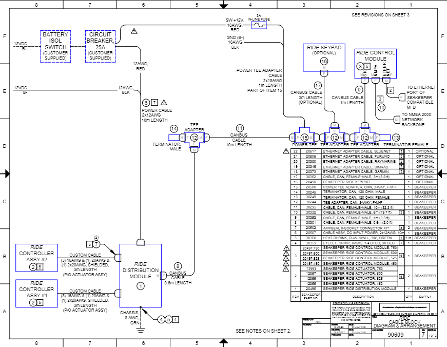
3. Drawings
4. Tools and Equipment Needed
4.1. Equipment
- 25 Amp Circuit Breaker or Fuse
- 8-Gauge Grounding Wire
- 12-Gauge Power Wire Copper Tinned (Optional)
- Adhesive-Lined Heat Shrink (for power cables)
4.2. Tools
- Drill
- Level
- 1/8 in. Drill Bit
- 1/4 in. Drill Bit
- Phillips Head Screwdriver
- Oscillating Tool or Jig Saw
- Heat Gun
- Crimpers
- Wire Strippers
- Terminals for Cable-to-Battery Connection
- Work Light or Flashlight
- Fish Tape or Electricians Snake
4.3. Boat Features Requirements
- 12 Volt Power Controlled by Battery Isolation Switch/Keyswitch
- GPS with NMEA 2000 Network Backbone
- Seakeeper Compatible MFD
- Ensure the MFD has the latest version of the Seakeeper software before using the Seakeeper Ride system
5. Inventory Parts
Please ensure all parts are present in the package before proceeding. If any parts are missing, contact the seller.
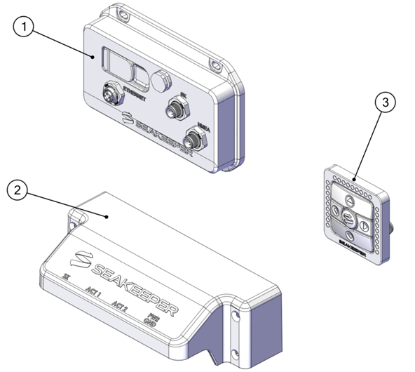
1. Software Module
2. Distribution Module
3. Keypad (Optional, Purchased Separately)
Table 1 – Electrical Mounting and Wiring Components
| Software Module Mounting Hardware | Distribution Module Mounting Hardware | ||
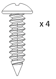 Phillips No. 10 x 1 in. Screw | 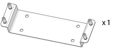 Distribution Module Mounting Bracket | 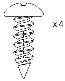 Phillips No. 12 x 0.75 in. Screw | 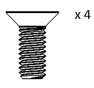 M4 x 10 mm Flat Head Socket Cap Screw |
| Distribution Module Wiring Components | |||
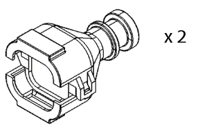 Ampseal Housing Backshell | 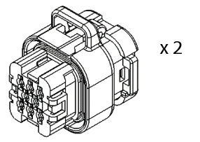 Ampseal Housing | 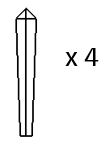 Ampseal Cavity Sealing Plug | 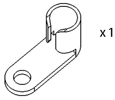 90 Degree Crimp Connect |
| Distribution Module Wiring Components Cont. | |||
 Controller Cable Heat Shrink 0.75 x 1.5 in. |  Grounding Wire Heat Shrink 0.375 x 1 in. | 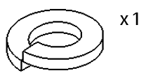 M6 Grounding Split Lock Washer | 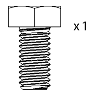 M6-1.0 x 12 mm Hex Head Grounding Screw |
| Seakeeper Ride Proprietary CAN Bus Components | |||
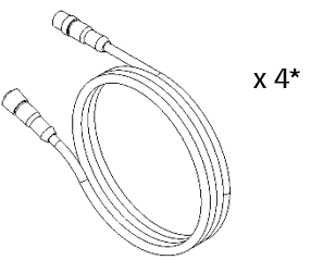 Double Ended NMEA 2000 Cable *Lengths 0.6, 1, 6, 10 m (2.0, 3.3, 19.7, 32.8 ft) | 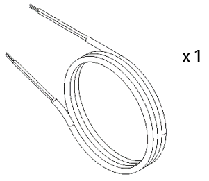 Distribution Module Power Cable | 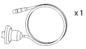 Ethernet Adapter Cable (Purchased Separately) | 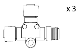 CAN Bus Tee |
| Seakeeper Ride Proprietary CAN Bus Components Cont. | |||
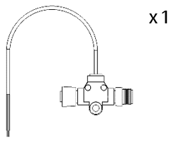 Powered CAN Bus Tee | 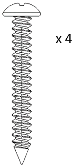 Phillips No. 6 x 1.25 in. Screw | 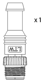 Male CAN Bus Terminator | 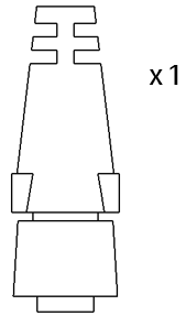 Female CAN Bus Terminator |
| Keypad Components (Optional) | |||
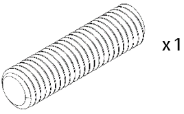 M8 Threaded Stud | 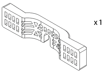 Keypad Mounting Bracket | 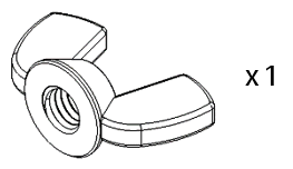 M8 Wingnut | 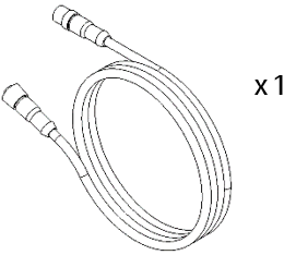 Double Ended NMEA 2000 Cable 3 m (9.8 ft) |
6. Component Details and Installation Location
Component Details and Installation Location Introduction
Selecting a proper location for the Software Module is critical to the successful and safe function of the system. Selection of mounting location on the boat should adhere to the guidelines in this section.
6.1. Software Module
The Software Module must be mounted on a structurally sound vertical surface. Vibration or shaking of this mounting surface is unacceptable and may cause the system to malfunction.
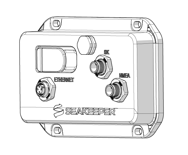
A minimum of 5 in. (12.7 cm) of clearance is required on the cable connection side the Software Module to allow for proper installation of cables.
The Software Module needs to be level to both port/starboard and bow/stern. The Software Module can accept up to 15 degrees of offset in both planes. Due to the Software Module being responsible for measuring the roll, pitch, and yaw of the vessel, leveling is imperative for maximum performance of the Seakeeper Ride system.
When checking the level of the unit during installation, it is best to have the boat level port/starboard and the forward/aft trim equal to the boat’s waterline when at rest. This can be accomplished on a trailer, on jack stands, lifts, or floating in calm water.
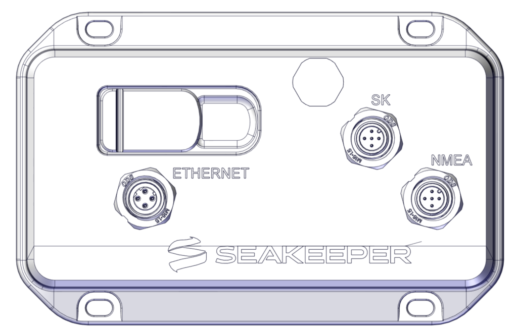
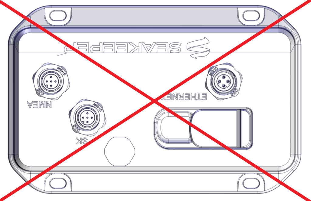
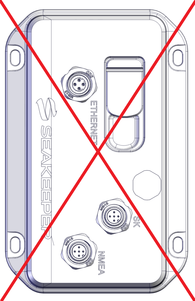
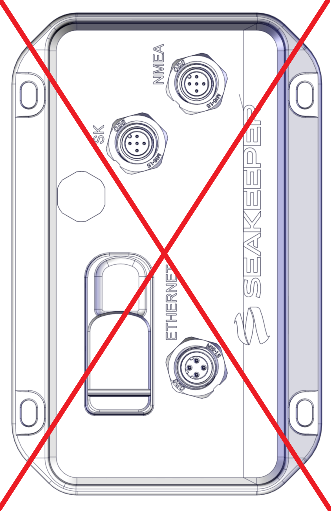
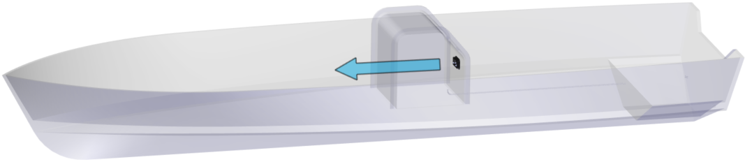
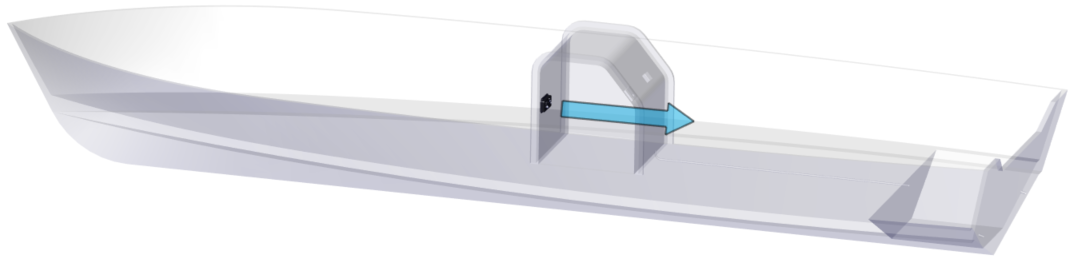
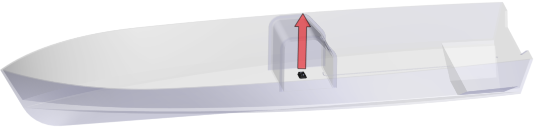
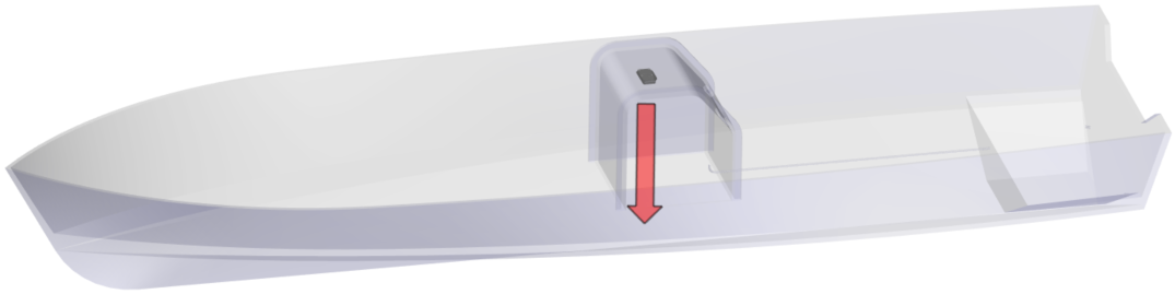
 IMPORTANT: Since the Software Module contains the motion sensor, IT MUST be mounted with the Seakeeper logo upright and facing either forward or aft (the logo CAN NOT be facing either side of the boat). Mount the Software Module as close to the operator as possible.
The Software Module should be readily accessible for software updates.
Warning: The stabilization system in the Software Module relies on fine movements and vibrations in the boat to provide unprecedented stability control. Speakers are of great concern due to the vibrations induced on the mounting surfaces.
6.2. Distribution Module
The Distribution Module provides power and communication to the Seakeeper Ride Controllers mounted to the transom. The Distribution Module should be installed on a structurally sound vertical surface, mounted with the Seakeeper logo upright.
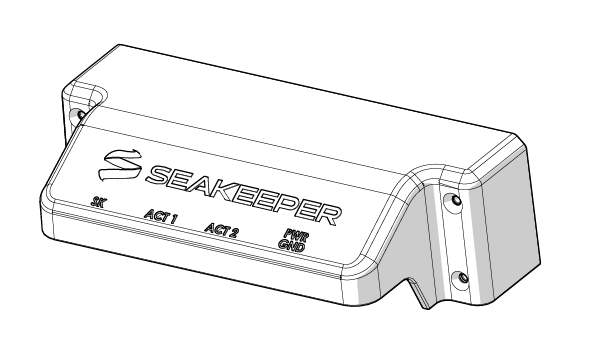
A minimum of 5 in. (12.7 cm) of clearance is required beneath the Distribution Module to allow for proper installation of cables.
The Distribution Module must be mounted close to both Controllers, as the Actuator Cables are 10 feet (3.0 meters) long. To accommodate the cable length, the Distribution Module should be mounted in the stern of the boat as high as practical to minimize exposure to bilge water.
Note: Actuator Cables cannot be extended due to power loss restrictions.
6.3. Keypad (Optional)
The optional Keypad sold separately is designed to be installed at the helm for the vessel operator to make manuals trim and list adjustments.
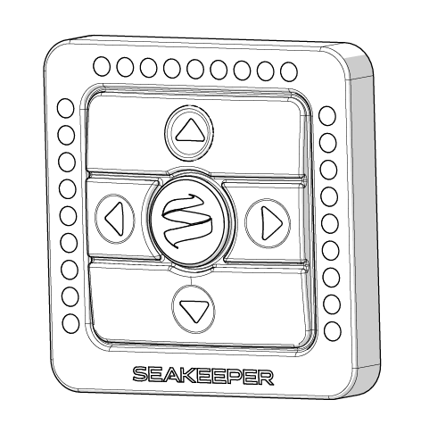
Select a location on the dashboard for the Keypad. Overall Dimensions of the keypad are 2.65 in X 2.65 in (67.3 mm X 67.3 mm).
The Keypad provides functionality when the system is in Auto and Manual modes. When the system is in Manual mode, it behaves as a static list/trim control system. Please refer to the Operation Manual and/or the Quick Start Guide for more information on using the Keypad.
6.4. Seakeeper Ride Proprietary CAN Bus
Seakeeper Ride uses a unique signal to communicate between the components in the system. Though NMEA 2000 cables and connectors are used, the Seakeeper Ride Proprietary CAN Bus must be separate from the boat’s Navigation NMEA 2000 backbone. Be sure to distinguish the two CAN Bus networks when performing the electrical installation.
Ensure the Seakeeper Ride Proprietary CAN Bus is readily accessible for maintenance and service, near the Software Module.
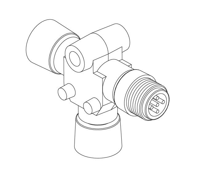
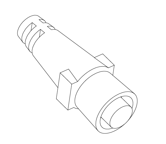
Figure 6 – NMEA Tee and Terminator
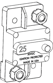
6.5. 25 Amp Circuit Breaker or Fuse
For protection of the Seakeeper Ride system and general safety, the positive end of the Distribution Module’s Power Cable must be wired to a 25 Amp Circuit Breaker or fuse, which is not included. The Circuit Breaker or fuse should be readily accessible. We recommend mounting this close to the Software Module for quick inspection and power cycling when necessary.

FAILURE TO UTILIZE A 25 AMP CIRCUIT BREAKER OR FUSE COULD CREATE A FIRE RISK.
7. Mounting
7.1. Software Module Mounting
- Trace Mounting Holes. Based on the selection criteria (Section 6.1) for mounting location, hold the Software Module in the designated location. Using a writing utensil, mark the location of the four (4) mounting holes located in each corner.
- Drill Holes. Prior to drilling the pilot holes, confirm that the mounting surface is greater than 1 in. (25.4 mm) thick. Once the depth has been confirmed, drill pilot holes for each of the four (4) positioning screws using a 1/8 in. drill bit approximately 3/4 in. (15.9 mm) deep.
- Insert Screws. Hold the Software Module in place and using a screwdriver, install the four (4) Phillips No. 10 x 1 in. screws. Ensure the Seakeeper logo is upright, and mounting is secured.
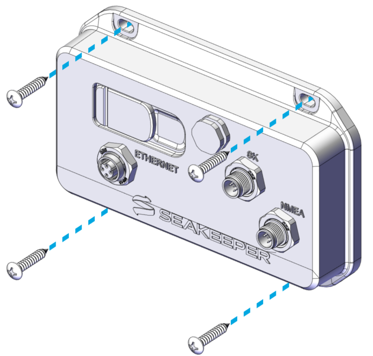
 IMPORTANT: The Software Module MUST be mounted with the Seakeeper logo upright and facing either forward or aft (the logo CAN NOT be facing either side of the boat). The Software Module CAN NOT be mounted on the floor. Mount the Software Module as close to the operator as possible.
7.2. Distribution Module Mounting
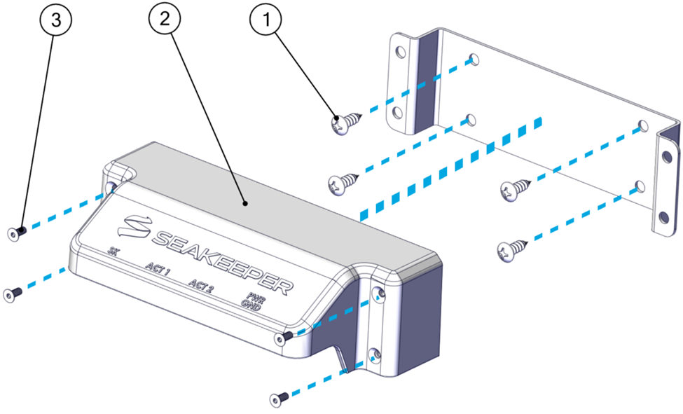
- Trace Mounting Holes. Based on the selection criteria for mounting location (Section 6.2), hold the Distribution Module Mounting Bracket in place. Mark the location of the four (4) inner mounting holes using a writing utensil.
- Drill Holes. Prior to drilling the pilot holes, confirm that the mounting surface is greater than 3/4 in. (19 mm) thick. Once the depth has been confirmed, drill pilot holes for each of the four (4) positioning screws using a 1/8 in. drill bit approximately 5/8 in. (19 mm) deep.
- Insert Screws. Hold the Distribution Module bracket in place. Using a screwdriver, install the four (4) Phillips No. 12 x 0.75 in. mounting screws.
- Mount Distribution Module. Once the bracket is in place, slip the Distribution Module on top of the Mounting Bracket. Use the four (4) M4 x 10 mm flat head socket cap screws to install the Distribution Module onto the bracket with a 2.5 mm hex key and tighten.
7.3. Keypad Mounting (Optional)
Note: The Keypad is not necessary for the operation of Seakeeper Ride. All Keypad controls can be found on the MFD application. Prior to cutting and drilling, ensure no objects are behind the surface that you do not intend to cut during the procedure.
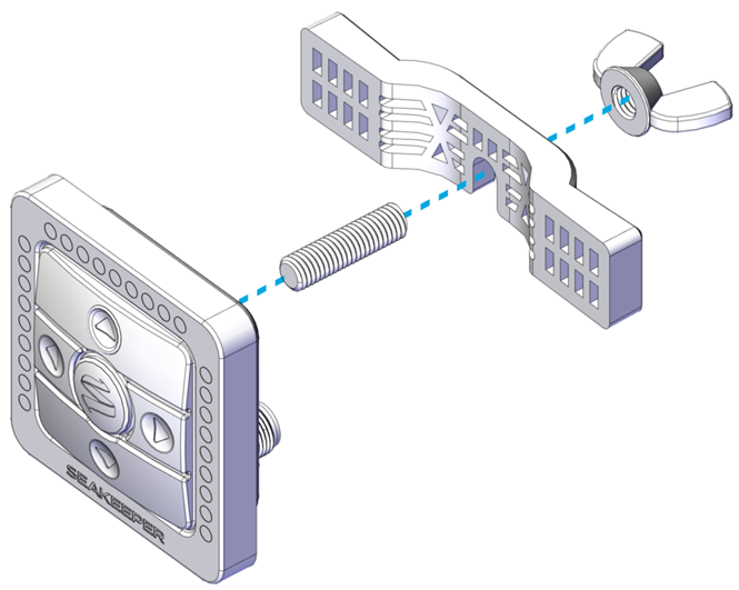
- Trace Mounting Holes. Find and print the full-scale template of the Keypad to assist with tracing HERE, verifying the printed size is correct (the square is 2.25 in. X 2.25 in. [57.2 mm X 57.2 mm]). Tape the template in the desired mounting location. This will be used to create the square cutout for the Keypad to be inserted into.
- Drill Holes. Drill 1/4 in. holes through the mounting surface in each corner of the square. Hole locations are shown on the template by the circles in the corners.
- Cut Lines. Using a jigsaw or oscillating tool, cut along the remaining perimeter of the solid square.
- Mount Keypad. Thread the provided stud onto the Keypad. Screw the M8 Wing Nut onto the stud, leaving room to accommodate the Mounting Bracket between the Keypad and Wing Nut. Align the Keypad so the Logo is at the bottom, facing the vessel operator. Slide the Keypad Mounting Bracket onto the stud between the Wing Nut and the Keypad. Tighten the Wing Nut to hold the bracket in place.
8. Wiring and Terminating Cables
Wiring Introduction

WARNING! Seakeeper Ride is critically dependent on these steps for the system to operate as intended. The installer must review the electrical drawings in Section 3 before terminating wiring. INCORRECT WIRING MAY RESULT IN DESTRUCTION OF EQUIPMENT, DAMAGE TO THE BOAT OR OTHER PROPERTY, SERIOUS INJURY OR DEATH.
8.1. Seakeeper Ride Proprietary CAN Bus
Seakeeper Ride requires two (2) CAN Bus Tees, one (1) CAN Bus Powered Tee, one (1) NMEA 2000 Cable, one (1) Male CAN Bus Terminator, and one (1) Female CAN Bus Terminator. A third CAN Bus Tee will be provided with the optional Keypad sold separately. These components together form the Seakeeper Ride Proprietary CAN Bus and provide communication across the system. Each component must be installed correctly for Seakeeper Ride to function.
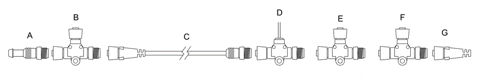
A. Male Terminator
B. Tee to Distribution Module
C. 10 m (32.8 ft) Cable to Distribution Module
D. Powered Tee
E. Tee to Keypad (Optional)
F. Tee to Software Module
G. Female Terminator
Figure 11 – Seakeeper CAN Bus Tees and Terminators
CAN Bus Tees and Cable
The CAN Bus Tees (B, E, and F in Figure 11) are connection points for the major electronic components of the Seakeeper Ride system. The 10 m (32.8 ft) NMEA 2000 Cable (C in Figure 11) allows the CAN Bus to run to the stern of the boat where the Distribution Module is located. The supplied Phillips No. 6 x 1.25 in. screws are for mounting the CAN Bus Tees to the boat.
Powered CAN Bus Tee
The Powered Tee (D in Figure 11) is responsible for providing power to the proprietary CAN Bus.
The black wire should be grounded.
The red wire should be connected to a 12 V power source, which may be through a battery isolation switch or the boat’s key switch. That this power must be able to be cycled off and on during setup and diagnostic procedures. Some engine manufacturers key switch power is inconsistent during engine start, causing a drop in power to Seakeeper Ride equipment, resulting in Seakeeper Ride system turning off. In these cases, moving the Seakeeper Ride Powered CAN Bus Tee to a battery isolation switch is recommended.
Ensure the 3A inline fuse between the Key and Power Tee is not removed during installation.
WARNING! Do not reverse the polarity of the CAN Bus Tees. INCORRECT WIRING, SUCH AS THIS, MAY RESULT IN DESTRUCTION OF EQUIPMENT, DAMAGE TO THE BOAT OR OTHER PROPERTY, SERIOUS INJURY OR DEATH.
CAN Bus Terminators
On one end of the Seakeeper Ride Proprietary CAN Bus, install a Male Terminator, and on the opposite end, install a Female Terminator (A and G in Figure 11).
One CAN Bus Terminator must be installed within three (3) feet of the Software Module. One CAN Bus Terminator must be installed within three (3) feet of the Distribution Module. The result of this CAN Bus configuration is a long cable from the Tee chain (D, E & F in Figure 11) in the console to the final Tee in the aft end of the boat near the Distribution Module. This configuration builds a stable network.
8.2. Software Module Wiring
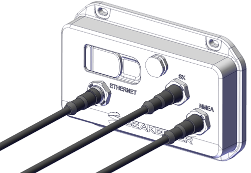
Seakeeper Ride Proprietary CAN Bus Cable
Connect a NMEA 2000 cable between the Software Module attachment point labeled “SK,” and the Seakeeper CAN Bus Tee (F in Figure 11). The 3.3 ft (1 m) cable supplied is recommended.
On the male end of this CAN Bus Tee, attach a Female Terminator (G in Figure 11).
Seakeeper Proprietary CAN Bus negative wire will need Clean Ground because, it cannot go through the engine manufacturers wiring harness or it will lose power when engine is started.
NMEA 2000 Network
From the side of the Software Module labeled “NMEA,” attach a NMEA 2000 cable to the boat’s NMEA 2000 Network Backbone. The 19.7 ft (6 m) cable supplied is recommended.
This may require a new Tee added to the backbone (not included).
Be sure to follow NMEA Backbone protocol and observe Terminator and Tee requirements.
Ethernet Connection
From the port side of the Software Module labeled “Ethernet,” attach the Ethernet Adapter Cable that suits the boat’s Multifunction Display. This cable must be purchased separately from Seakeeper.
8.3. Distribution Module Wiring
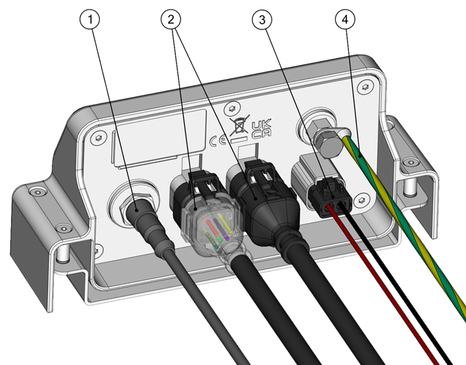
- Seakeeper CAN Bus
- Controller Cables
- Power Cable
- Ground Wire
Seakeeper Ride Proprietary CAN Bus Cable
Connect one end of the supplied NMEA 2000 Cable to the Distribution Module. Connect the other end of the NMEA 2000 Cable to the CAN Bus Tee (B in Figure 11). The supplied 0.6 m (2 ft) Cable is recommended. Ensure a Male Terminator (A in Figure 11) is installed at the this end of the CAN Bus Tee.
Controller Cables
The Controllers arrive with a custom cable appropriate for installation in the most challenging areas of a boat. The cables are resistant to water, oil, and electromagnetic interference.
Note: This cable is not to be modified. Do not allow acetone to come in contact with the Controller Cable Gland Sealing Nut (Figure 56 in the Mechanical Installation Manual)

ATTENTION: When inserting cable end pins into the Ampseal Plug, please use caution. Damage to these pins will result in Actuator replacement.
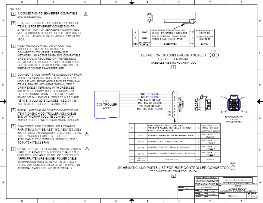
The cable ends must be inserted into the Ampseal plug. Slide shrink wrap over the wire prior to inserting cable ends. Ensure the wedge lock on the Ampseal Plug Housing is open. Follow Drawing No. 90609 – Seakeeper Ride Cable Block Diagram and Figure 14 for specific color to pin number identification. Review these written instructions, and this video from Ampseal for best practices. If ports 7 and 8 are accidentally pierced, be sure to insert Ampseal Cavity Sealing Plugs to prevent water from entering. Close the wedge lock by squeezing it firmly onto the Ampseal Plug Housing.
Once the pins are secured in the Ampseal plug, apply the heat shrink over the point where the cables meet the Ampseal plug. The plug is then ready to be attached to the Distribution Module. Do not connect the Controller Cables to the Distribution Module at this point. The cables will be connected during the commissioning procedure for proper programming and identification.
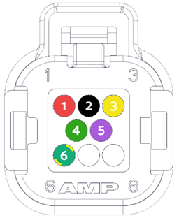
1. RED, +V (16 AWG)
2. BLACK, 0V (16 AWG)
3. YELLOW, CAN_HI (20 AWG)
4. GREEN, CAN-LO (20 AWG)
5. PURPLE, WAKE (20 AWG)
6. GREEN/YELLOW, GND (16 AWG)
(7 and 8 are left blank or have plugs if pierced.)
ATTENTION! The specific color to pin number identification is critical. Incorrect placement may result in destruction of the Actuator.
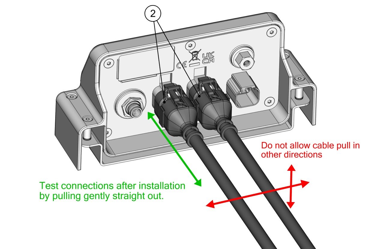
When connecting the Controller Cables during commissioning, test to make sure they are attached correctly. Controller Cables should click in and fit firmly once inserted. When Controller Cables are secured, gently pull straight out to ensure they do not come out. To ensure the cables remain properly attached, do not allow the cables to be pulled in any other direction at any time.
Ground Wire
The ground wire cable attaches the Distribution Module to the vessel’s common ground. Attach the loose eyelet of this cable to the common ground of the boat. The ground wire should be wired to bus bar going straight to the battery. Do not ground through another electrical system on the boat.
This cable must be 8 AWG or larger.

WARNING! Do not squeeze or crimp the cables too tightly or they could fail.
Power Cable
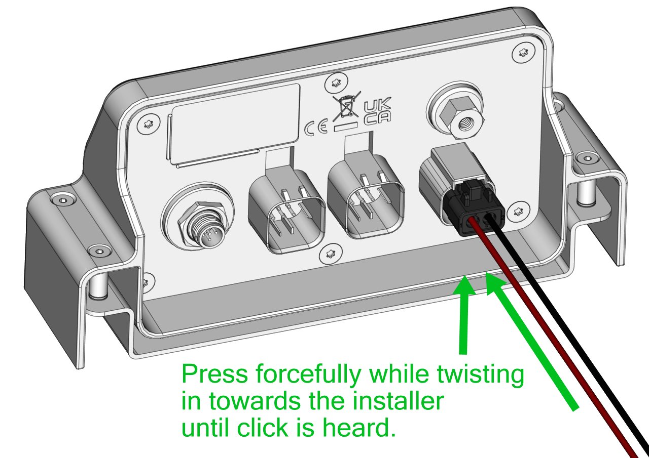
The power cable provides power to the Distribution Module so the Controllers can move as needed. The power cable is made up of two (2) 12 AWG wires, one red and one black.
The black wire is to be attached to the negative terminal of the vessel’s 12 V power, and the red wire is to be attached to a 25 A circuit breaker or fuse. The power to the circuit breaker or fuse is to be supplied by the vessel’s battery isolation switch and the positive side of 12 V power.
WARNING! Do not reverse the polarity of the Power Cable. INCORRECT WIRING, SUCH AS THIS, MAY RESULT IN DESTRUCTION OF EQUIPMENT, DAMAGE TO THE BOAT OR OTHER PROPERTY, SERIOUS INJURY OR DEATH.
When connecting the power cable into the Distribution Module, press in forcefully while twisting in towards the installer until a small, audible clicking sound is heard. When the power cable is secured, gently pull straight out to ensure it does not come out.
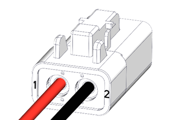
If the Power Cable is not used, choose a power cable that has at least 12 AWG wires to ensure sufficient power supply to the Actuators. Do not use a power cable longer than 10 m (32.8 ft), as the equipment is voltage-sensitive and current-sensitive. The power cable termination must be in a 2-pin Deutsch plug Part Number DTP06-2S with the red wire in terminal 1 and the black wire in terminal 2 as shown below. Review this video from Deutsch for best practices.
8.4. Keypad Wiring (Optional)
Connect a NMEA 2000 cable to the Keypad and Seakeeper Ride CAN Bus Tee (E in Figure 11) using the 3 m (6.6 ft) cable supplied.
You have now completed the electrical installation of the Seakeeper Ride system. Follow the instructions in the Seakeeper Ride Commission Instructions for the first start and calibration of the system.
9. NMEA Notes
The NMEA 2000 Load Equivalency Number (or LEN) of the Seakeeper Ride device is One (1).
NMEA Pinout for Seakeeper Ride:
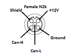
| NMEA Connector | Name | Color |
| 1 | No Connection | – |
| 2 | NET-S | Red |
| 3 | NET-C | Black |
| 4 | Data High | White |
| 5 | Data Low | Blue |
The Seakeeper Ride device will accept Command Group function commands on its NMEA Connection on the System Instance. It will also accept Command Group Function commands (on its NMEA Connection) on the Device Instance Upper and Device Instance Lower, but BOTH device instances parts must be commanded within the same command, or the command will be rejected. This device is also able to be reprogramed by a qualified technician. Doing this may change the System and Device Instances.