Electrical Installation Manual
8.1. Seakeeper Ride Proprietary CAN Bus
Seakeeper Ride requires two (2) CAN Bus Tees, one (1) CAN Bus Powered Tee, one (1) NMEA 2000 Cable, one (1) Male CAN Bus Terminator, and one (1) Female CAN Bus Terminator. A third CAN Bus Tee will be provided with the optional Keypad sold separately. These components together form the Seakeeper Ride Proprietary CAN Bus and provide communication across the system. Each component must be installed correctly for Seakeeper Ride to function.
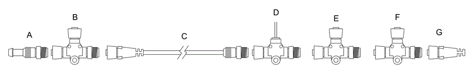
A. Male Terminator
B. Tee to Distribution Module
C. 10 m (32.8 ft) Cable to Distribution Module
D. Powered Tee
E. Tee to Keypad (Optional)
F. Tee to Software Module
G. Female Terminator
Figure 11 – Seakeeper CAN Bus Tees and Terminators
CAN Bus Tees and Cable
The CAN Bus Tees (B, E, and F in Figure 11) are connection points for the major electronic components of the Seakeeper Ride system. The 10 m (32.8 ft) NMEA 2000 Cable (C in Figure 11) allows the CAN Bus to run to the stern of the boat where the Distribution Module is located. The supplied Phillips No. 6 x 1.25 in. screws are for mounting the CAN Bus Tees to the boat.
Powered CAN Bus Tee
The Powered Tee (D in Figure 11) is responsible for providing power to the proprietary CAN Bus.
The black wire should be grounded.
The red wire should be connected to a 12 V power source, which may be through a battery isolation switch or the boat’s key switch. That this power must be able to be cycled off and on during setup and diagnostic procedures. Some engine manufacturers key switch power is inconsistent during engine start, causing a drop in power to Seakeeper Ride equipment, resulting in Seakeeper Ride system turning off. In these cases, moving the Seakeeper Ride Powered CAN Bus Tee to a battery isolation switch is recommended.
Ensure the 3A inline fuse between the Key and Power Tee is not removed during installation.

WARNING! Do not reverse the polarity of the CAN Bus Tees. INCORRECT WIRING, SUCH AS THIS, MAY RESULT IN DESTRUCTION OF EQUIPMENT, DAMAGE TO THE BOAT OR OTHER PROPERTY, SERIOUS INJURY OR DEATH.
CAN Bus Terminators
On one end of the Seakeeper Ride Proprietary CAN Bus, install a Male Terminator, and on the opposite end, install a Female Terminator (A and G in Figure 11).
One CAN Bus Terminator must be installed within three (3) feet of the Software Module. One CAN Bus Terminator must be installed within three (3) feet of the Distribution Module. The result of this CAN Bus configuration is a long cable from the Tee chain (D, E & F in Figure 11) in the console to the final Tee in the aft end of the boat near the Distribution Module. This configuration builds a stable network.