Seakeeper 35 / 30HD Installation Manual (90268-7)
Bolt-In Installation
Check and Preparation of Hull Structure
Refer to Seakeeper Drawing No. 90256 – Seakeeper 35/30HD Bolt-In Installation Details. Important dimensional and load information is given in this drawing that will impact the design details of the structure that will receive the Seakeeper. It is assumed that a proper structural analysis has been performed for the hull structure to which the Seakeeper will be fastened to ensure proper strength margins for the loads the Seakeeper will create during operation.
The hull structure supporting the Seakeeper should be arranged so the Seakeeper is parallel to the waterline in the forward-aft and port-starboard directions . In addition, the four areas on top of the beams on which the isolation mounts will rest, need to be co-planar within 1/8 in. (3 mm) to minimize potential distortion of Seakeeper support frame when installed. (Similar to Figure 12).
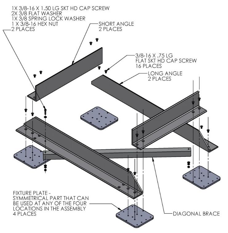
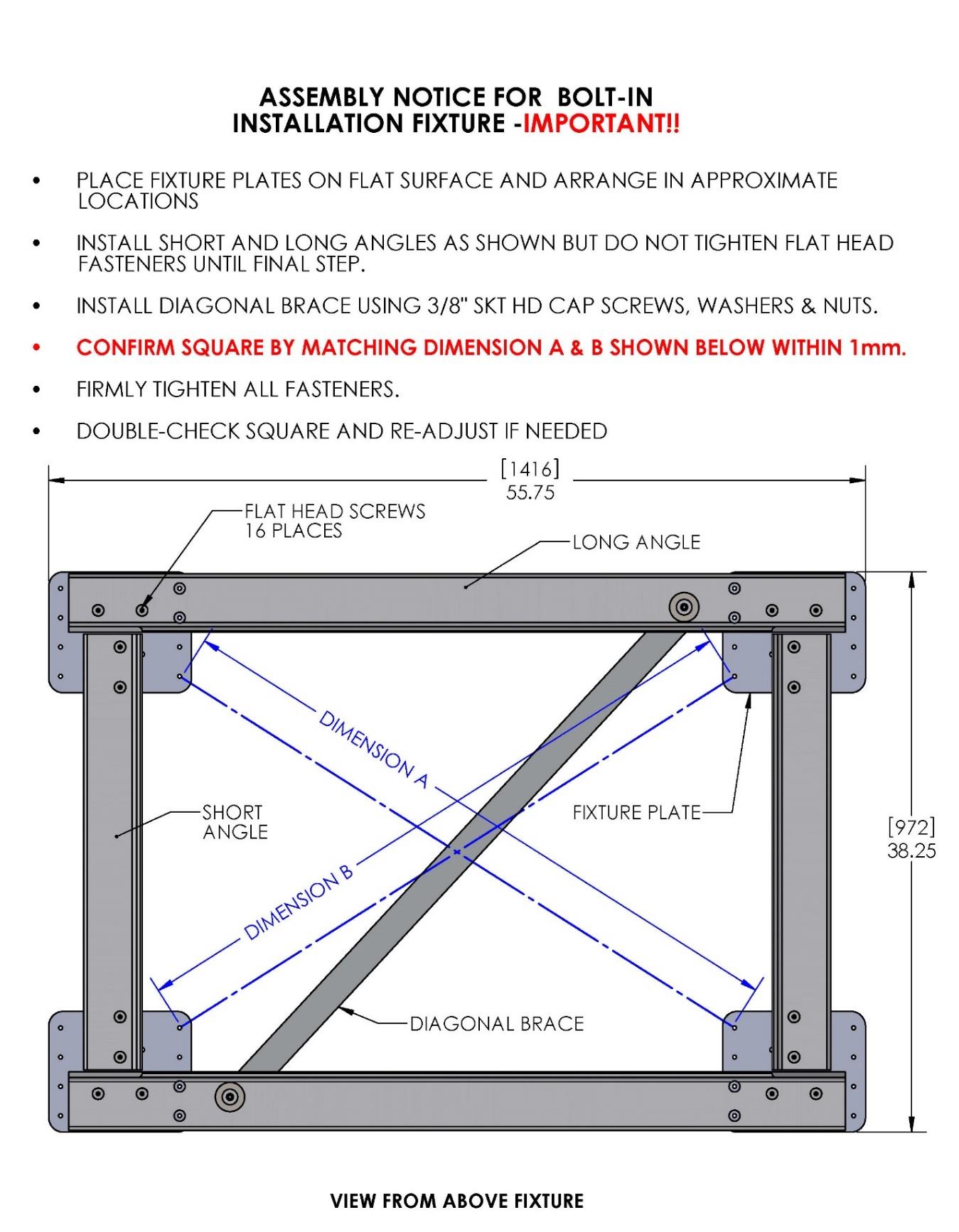
Seakeeper provides an installation fixture assembly (P/N 90089), which contains four plates that mimic the mating surfaces of the four isolation mounts located on the Seakeeper’s foundation. These plates have 8 holes located at the same centers as the holes in the isolation mounts. These smaller holes can be used to locate the holes in the ship’s structure through use of a transfer punch or drill. The fixture locates the hole patterns at the proper spacing, both in the fore-aft direction and the port-starboard direction. See Figures 4 & 5 below. Once assembled, the fixture can be used to check clearances and alignment of the hull structure.
Note: Do NOT use the installation fixture to establish Seakeeper envelope dimensions. Refer to Drawing No. 90256 – Seakeeper 35/30HD Bolt-In Installation Details, for envelope dimensions. A 3-D model of the Seakeeper is available on the Seakeeper website (www.seakeeper.com) to aid in designing the Seakeeper foundation and the space around the Seakeeper. See Figure 6 below.
CAUTION: Tight clearances from cable guide bands to hull structure. See above figure for dimensions and reference Seakeeper Drawing No. 90256 – Seakeeper 35/30HD Bolt-In Installation Details, for complete envelope.
Transfer of Holes to Boat Structure
- Lower assembled fixture onto hull structure.
- The four areas where the isolation mounts will rest should be coplanar to within 1/8 in. (3 mm). See figure below. Do not use the fixture to check co-planarity as it is not stiff enough.
- Align fixture in desired location and transfer holes from fixture plate to the hull structure. A transfer punch is recommended for this step. Note that holes in fixture plate are ø.257 in. (6.5 mm).
- Remove fixture and drill holes in hull structure at marked locations to mate with holes in Seakeeper isolation mounts. A ø.689 in. (17.5 mm) hole is recommended for the provided M16 fasteners.
NOTE: Certain foundation designs that employ threaded blind holes in thick plates may require the installer to obtain alternate fasteners.
Installation of Seakeeper
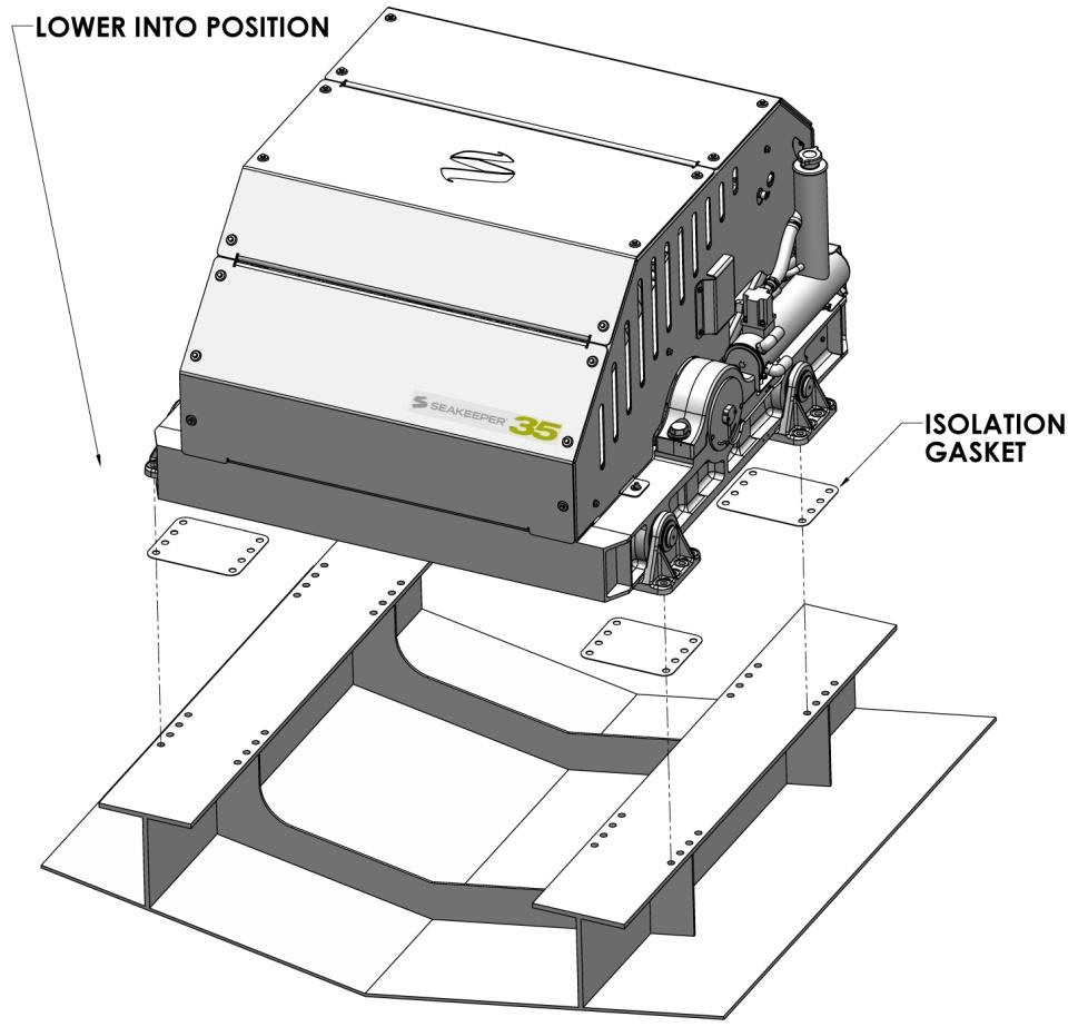
- Locate and position 4 isolation gaskets onto foundation beams (for metal to metal contacts only).
NOTE: A VERY SMALL AMOUNT OF SEALANT MAY BE APPLIED TO THE GASKET TO KEEP WATER FROM WICKING INTO THE JOINT. - Lower Seakeeper into position onto foundation beams and align over drilled holes.
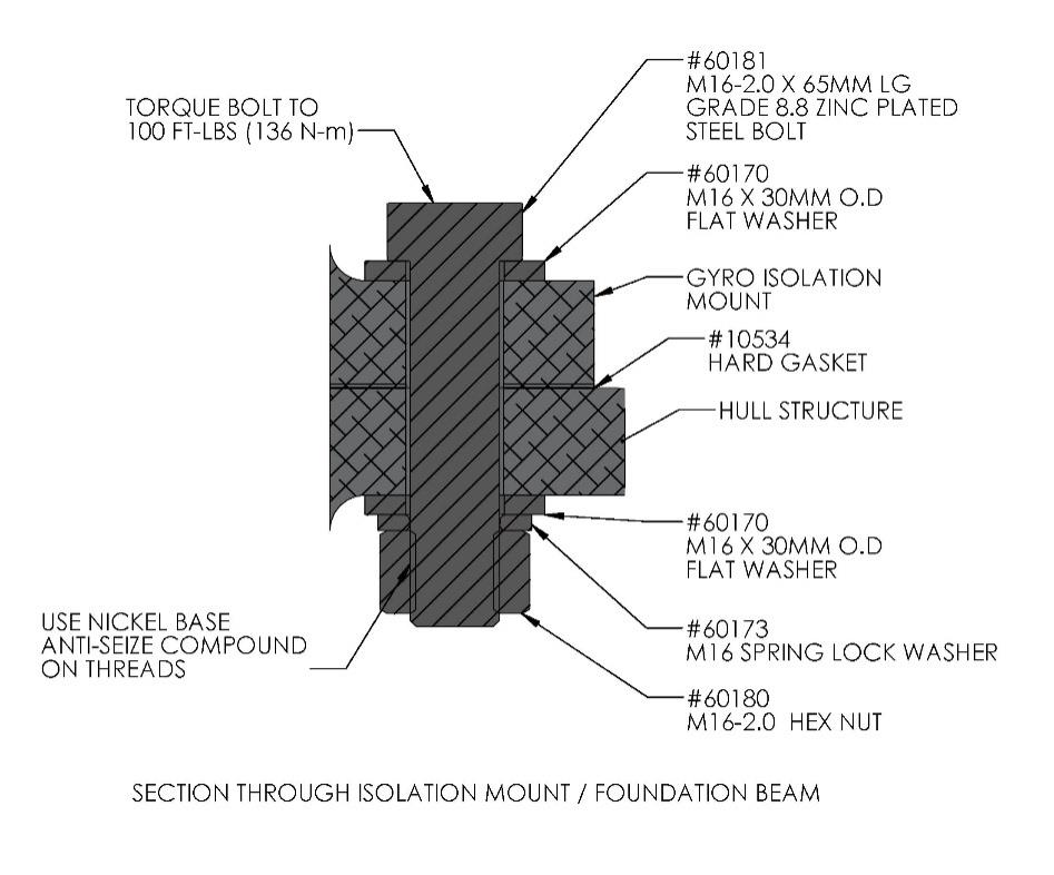
- Install Seakeeper supplied M16 fasteners as shown in figure below – apply a moderate coat of nickel based anti-seize compound to the threads of each bolt prior to installation and a small amount of sealant to the washer faces.
- Torque all fasteners to 100 ft-lbs (136 N-m).
- Proceed to electrical and cooling portion of the installation.