Seakeeper 35 / 30HD Installation Manual (90268-7)
Electrical Installation
Electrical Installation Introduction
This section for electrical installation explains how to mount the electrical equipment and how to connect the electrical cables.
Reference Documents & Drawings:
Link to Seakeeper 35/30HD Reference Documents
- 90233 – Seakeeper 35 Hardware Scope of Supply
- 90417 – Seakeeper 30HD Hardware Scope of Supply
- 90269 – Seakeeper 35/30HD Operation Manual
- 90467 – 2nd Helm Control Station Kit
- 90288 – Seakeeper 35/30HD Cable Block Diagram (includes 2nd Display Kit)
- 90438 – 5″ Operator Display Envelope and Mounting Details
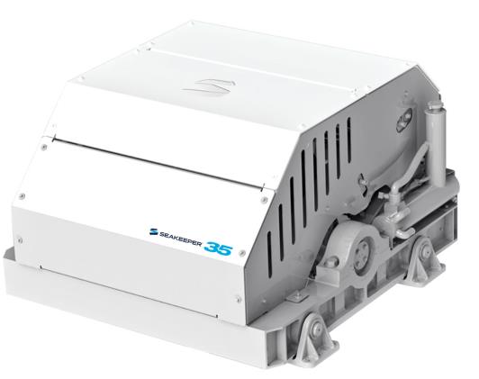
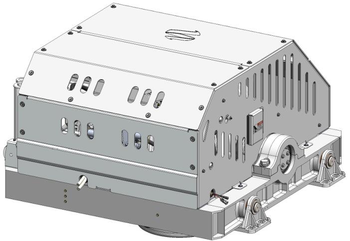
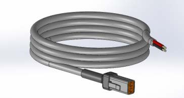
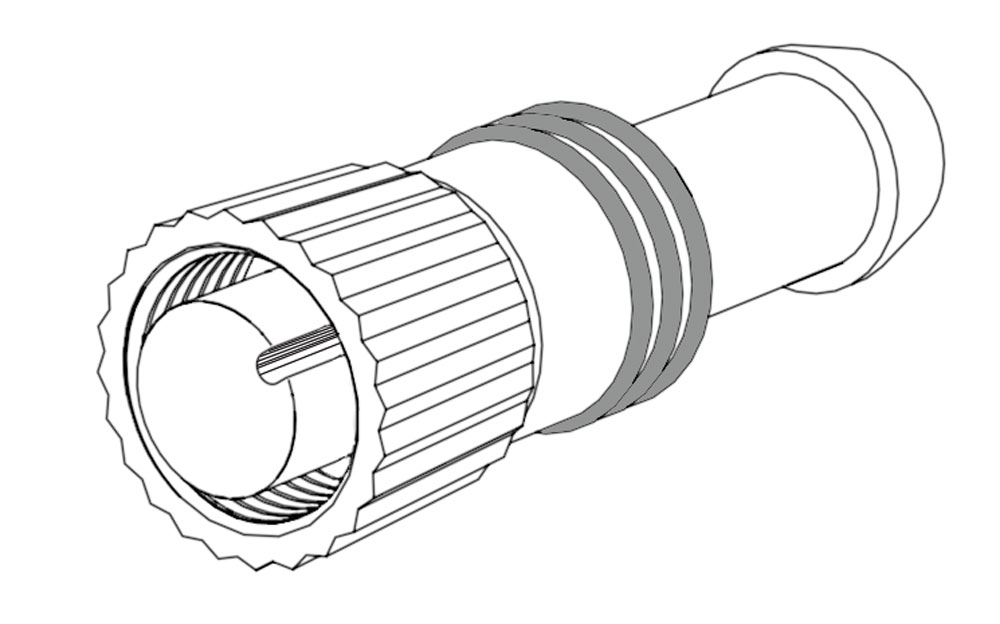
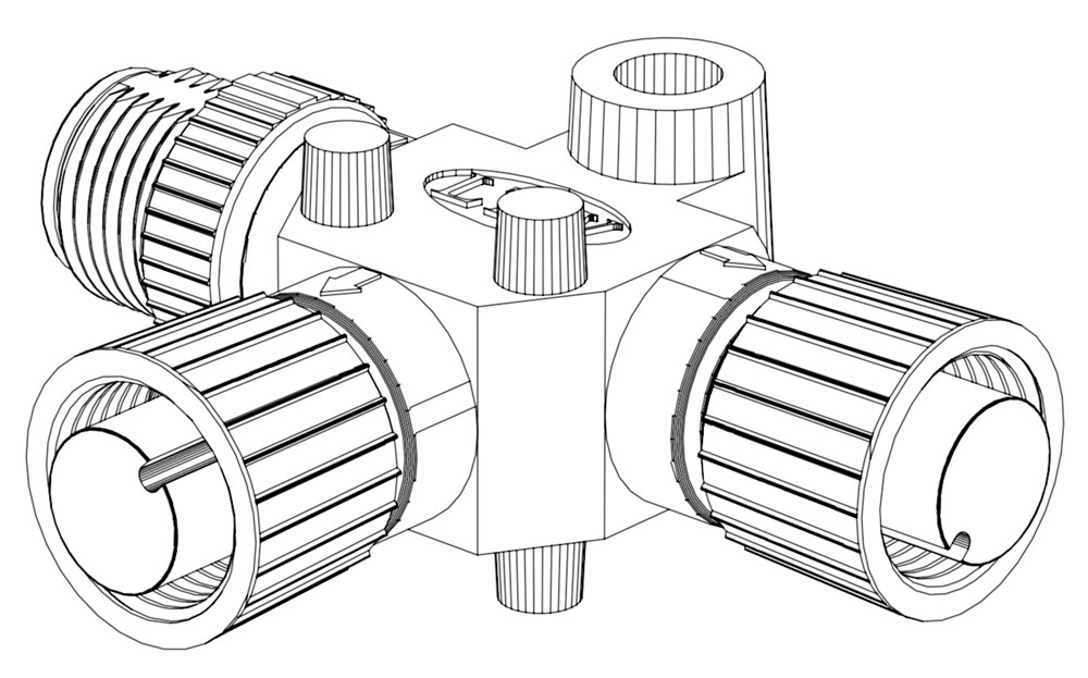

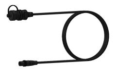
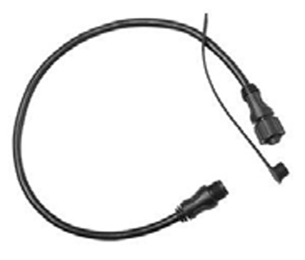
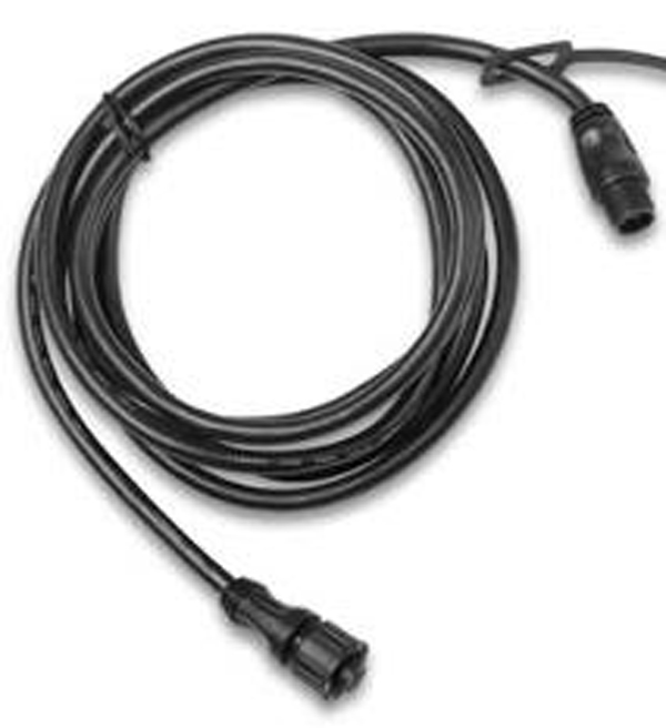
Figure 1 – Electrical Equipment for Seakeeper 35
Electrical Equipment Mounting
Precautions: Each item of electrical equipment has specific mounting instructions. These instructions
should be followed to ensure proper function of the Seakeeper.
Do NOT move Seakeeper mounted components from their
locations or incorrect Seakeeper operation will result.
- Touch Display Mounting Instructions, Surface Mount
- Console space required: Approx. 5.24 W x 3.70 H in. (133 x 94 mm)
- Mounting Instructions, Surface Mount: See Drawing No. 90438 – 5″ Operator Display Envelope and Mounting Details, for details.
- CAN Communications Tee Adapter and Terminator Mounting Instructions
- Console space required, Rear: Approx. 4 W x 3 H in. (102 x 76 mm)
- Mounting Instructions: Rear mount on vessel console panel, within 1 ft (0.3 m) of Display.
- Hardware required: One mounting screw for .197 in. (5 mm) diameter mounting hole on Tee Adapter.
- USB Extension Cable Assembly Mounting Instructions
- Console space required: Approx. 2 W x 2 H in. (51 x 51 mm), within 6 ft (2 m) from Touch Display.
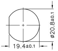
- Mounting Instructions, Surface Mount: Use panel cutout as shown in Section: Display Installation Template. Maximum panel thickness 1/8 in. (3.2 mm).
- Install sealed USB connector end of the extender cable assembly in panel from rear and secure with hex jam nut (provided) on front.
- Connect M12 connector end of the extender cable assembly to the rear of the Touch Display on receptacle AUX.
Electrical Equipment Power Connections
230 VAC Power Source Requirements
- 230 VAC (nominal), 1 Phase, 50/60 Hz, 30 A
- With installations of more than one Seakeeper, a separate circuit breaker should be used for each Seakeeper Motor Drive Box.
Drive Box AC Power Input Connection Instructions
- Cable: 3 x 10 AWG (3 x 6 mm2 CSA), 10 ft (3 m) length, Seakeeper supplied pre-installed.
- Locate Cable 2 for AC power input to the Motor Drive Box at the outward of three cable glands.
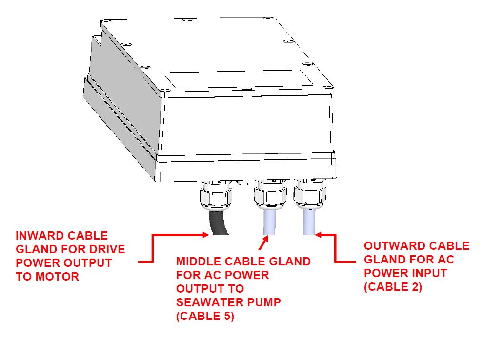
Figure 2 – Motor Drive Box AC Power Input & Output Cable Glands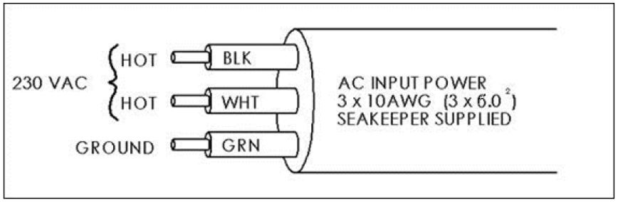
Figure 3 – Cable 2 Wire Connections at AC Power Distribution Panel - For Seakeeper 35, connect 230 VAC wires in Cable 2 to a 30 A, double-pole Circuit Breaker at an AC power distribution panel according to Figure 3 above.
- For Seakeeper 30HD, connect 230 VAC wires in Cable 2 to a 20 A, double-pole Circuit Breaker at an AC power distribution panel according to Figure 3 above.
- Locate Cable 2 for AC power input to the Motor Drive Box at the outward of three cable glands.
Drive Box AC Power Output to Seawater Pump Connection Instructions
- Cable: 3 x 10 AWG (3 x 6 mm2 CSA), 10 ft (3 m) length, Seakeeper supplied pre-installed.
- Pumps rated at 230 VAC, 5 A max., Customer-supplied.
 Verify that AC power is OFF to the Drive Box before connecting Cable 5 to a Seawater Pump.
- Locate Cable 5, for AC power output to the Seawater Pump from the Drive Box at the middle of three cable glands. (See Figure 2.)
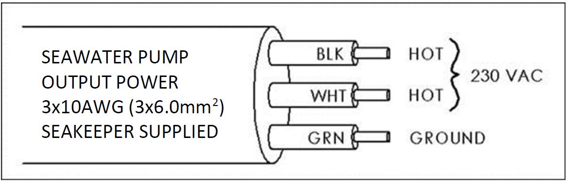
Figure 4 – Cable 5, AC Output Power Cable - Connect the 230 VAC wires in Cable 5 to a 5 A maximum, Seawater Pump (approximately 1/3 horsepower or 250 W) according to Figures 4 and 5.
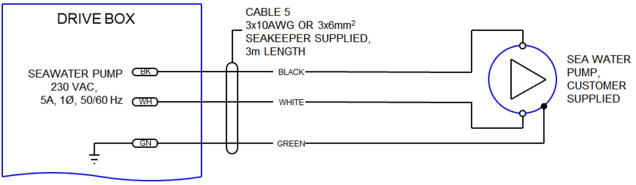
Figure 5 – Cable 5, Wire Connections to Seawater Pump
- Locate Cable 5, for AC power output to the Seawater Pump from the Drive Box at the middle of three cable glands. (See Figure 2.)
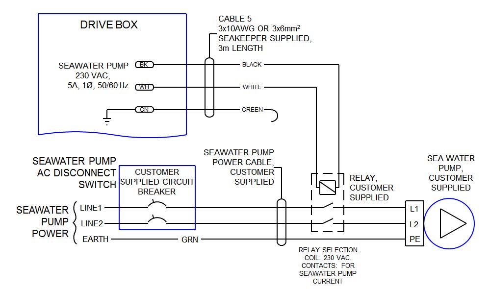
- If the customer-supplied Seawater Pump is not rated for 230 VAC, the Cable 5 output may be used to switch a customer-supplied relay.
- Locate Cable 5 for AC power output to the Seawater Pump from the Drive Box at the middle of three cable glands as shown in Figure 2.
- The recommended wiring is shown in Figure 6. Refer to Figure 4 for Cable 5 wire connections.
- If Cable 5 is not used, bundle cable and secure to Seakeeper frame or other area nearby which will not come in contact with moving parts during Seakeeper operation. Do NOT cut Cable 5 as it contains live voltage when Seakeeper is in operation. Seakeeper ships with Cable 5 permanently sealed at end of cable with protective cap in the event it is not used. Do NOT remove Cable 5 from Drive Box as moisture will be free to enter box through open cable gland and corrode internal electronic components
Cable 5 contains live voltage when Seakeeper is in operation. Do
NOT cut Cable 5. Do not remove Cable 5 from Drive Box.
24 VDC Power Source Requirements
- 24 VDC, 15 A
- A separate breaker should be used for each Seakeeper.
DC Power Connection Instructions
Reversing polarity on the DC power input to the Seakeeper can result in damaging the electronics in the control system.
- 24 VDC, 15 A, 2 x 12 AWG (3 x 4 mm2 CSA) Seakeeper supplied.
- Install Seakeeper provided DC Power Input Cable, P/N 20248, as Cable 1.
- Route Cable 1 to DC Power Distribution Panel.
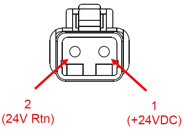
- Terminate red conductor to +24 VDC. Terminate black conductor to 24 V Rtn or 0 VDC.
- Before connecting Cable 1 to Seakeeper, check for proper voltage and polarity with a DC multimeter using Figure 7 below.
- Connect Cable 1 to 24 VDC input receptacle on Seakeeper.
- Install Seakeeper provided DC Power Input Cable, P/N 20248, as Cable 1.
When energizing DC power for the first time, if Display does not power up immediately then disconnect and inspect connector polarity.
Electrical Equipment Ground Connections
Seakeeper to Vessel Ground Connection Instructions
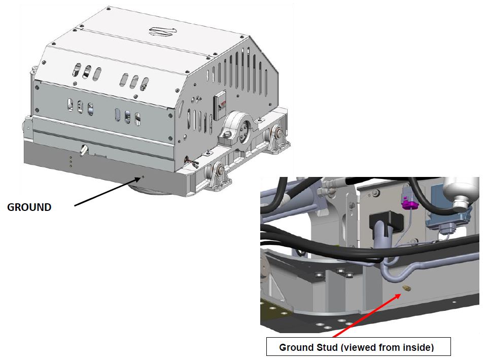
- Connect the Seakeeper foundation to vessel ground.
- Install Cable 6 (4 AWG or 22.0 mm2, Customer supplied) from the M6 brass ground stud on the Seakeeper rear foundation to a suitable vessel ground. Cable 6 should be installed on the inside rear of the foundation as shown below. If possible, install Cable 6 prior to installing the Seakeeper into the vessel. If there is no access to the ground stud from below the rear of the Seakeeper once installed, the rear cover, upper rear cover, and ECM bracket will need to be removed to access the ground stud from above the Seakeeper.
Operator Station
This section explains the connection between the Operator Station equipment and the Seakeeper.
Reference Documents & Drawings
- 90288 – Seakeeper 35/30HD Cable Block Diagram
Determine Location of Operator Station
- The desired location of the Operator Station must be determined with respect to the vessel arrangement.
- The operator display should be located on the bridge console.
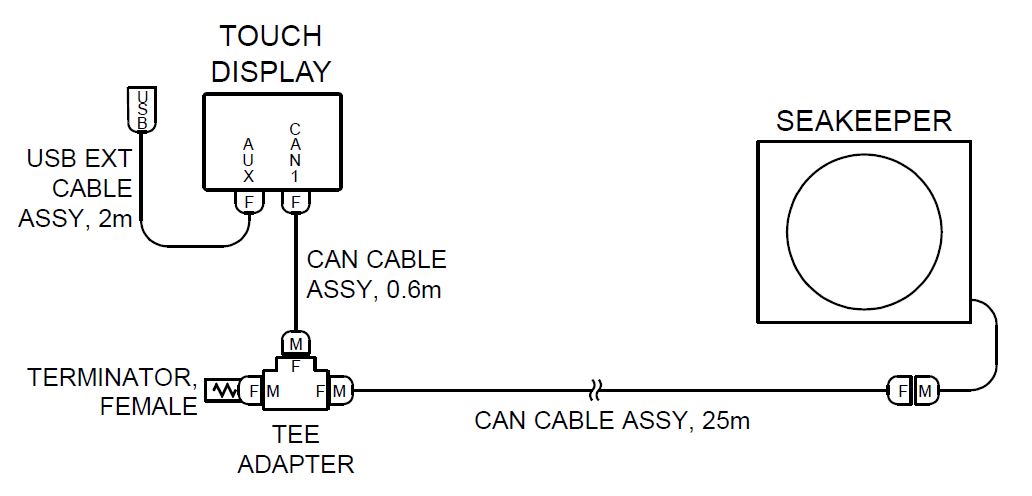
- Figure 9 below shows the CAN bus communications link for the Operator Station. The Terminator goes on the far end of the Tee Adapter from the Seakeeper.
Route Serial Communications Cable
- The CAN Cable Assembly (P/N 30243, Cable 3) is a 25 m shielded cable and the largest connector is a molded plug with maximum outer diameter of .58 in. (14.8 mm).
- Cable 3 must be routed and installed in the vessel from the Seakeeper (female end) to the Tee Adapter (male end) at the Operator Station.
Install Operator Station Equipment
- The Operator Station equipment is installed at the selected location using instructions found in Section: Electrical Equipment Mounting.
Connect Operator Station Equipment
- The Operator Station equipment is connected in accordance with Drawing No. 90288 – Seakeeper 35/30HD Cable Block Diagram.
Second Operator Station Connection
This section explains how to connect the 2nd Operator Station Kit.
Reference Documents & Drawings
- 90467 – Helm Display 2nd Operator Station Kit
- 90288 – Seakeeper 35/30HD Cable Block Diagram (includes detail of 2nd Operator Station)
Determine Location of 2nd Operator Station
- The desired location of the 2nd Operator Station must be determined with respect to the 1st Operator Station and the vessel arrangement.
- Typical locations include:
- Flybridge
- Engine room
Determine Cabling Arrangement
- Figure 10 below shows the entire serial communications link for 2 Operator Stations. The Terminator must be installed on the Tee Adapter farthest from the Seakeeper.
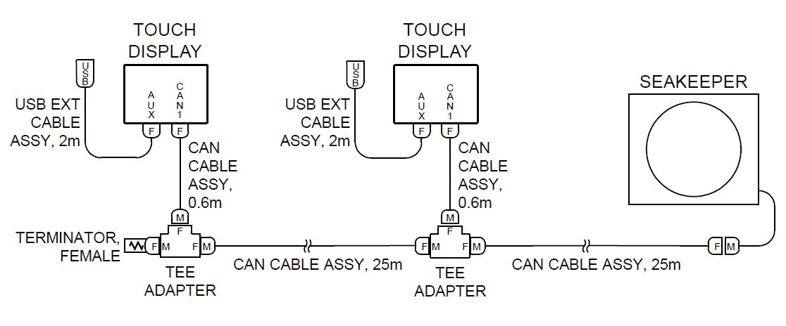
- The Operator Station nearest the Seakeeper should be connected to Cable 3.
Route 2nd Operator Station Cable
- A second CAN Cable Assembly (P/N 30243), also a 25 m shielded cable, and the largest connector is a molded plug with maximum outer diameter of .58 in. (14.8 mm).
- The additional CAN Cable Assembly must be routed in the vessel from the 1st Operator Station (female end) to the 2nd (male end) Operator Station.
Install 2nd Operator Station Equipment
- The 2nd Operator Station equipment is installed at the determined location using instructions found in Section: Electrical Equipment Mounting.
Connect 2nd Operator Station Equipment
- The 2nd Operator Station equipment is connected in accordance with Drawing No. 90288 – Seakeeper 35/30HD Cable Block Diagram.
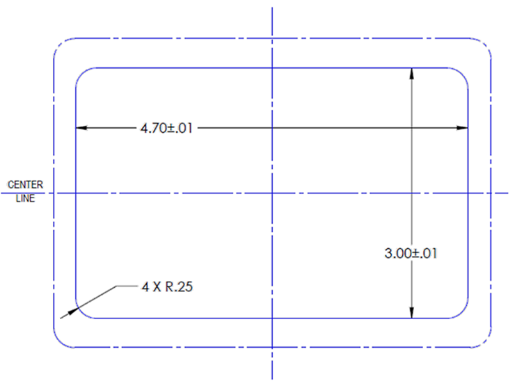
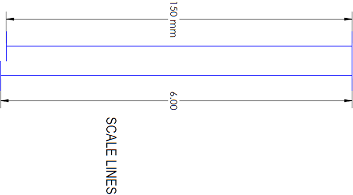
Display Installation Template
The following template is for mounting. Before using this template, measure to ensure that the shown size is actual.