Seakeeper 35 / 30HD Installation Manual (90268-7)
Electrical Equipment Power Connections
230 VAC Power Source Requirements
- 230 VAC (nominal), 1 Phase, 50/60 Hz, 30 A
- With installations of more than one Seakeeper, a separate circuit breaker should be used for each Seakeeper Motor Drive Box.
Drive Box AC Power Input Connection Instructions
- Cable: 3 x 10 AWG (3 x 6 mm2 CSA), 10 ft (3 m) length, Seakeeper supplied pre-installed.
- Locate Cable 2 for AC power input to the Motor Drive Box at the outward of three cable glands.
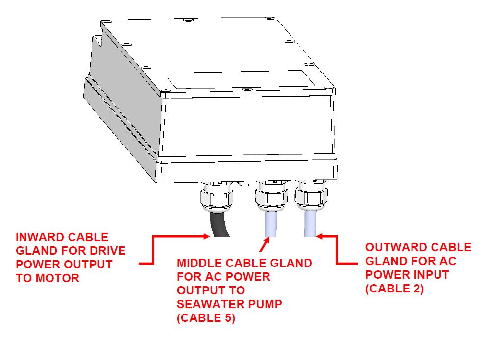
Figure 2 – Motor Drive Box AC Power Input & Output Cable Glands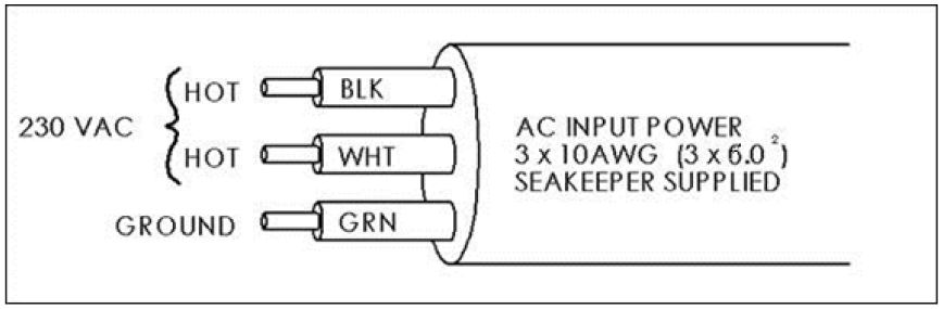
Figure 3 – Cable 2 Wire Connections at AC Power Distribution Panel - For Seakeeper 35, connect 230 VAC wires in Cable 2 to a 30 A, double-pole Circuit Breaker at an AC power distribution panel according to Figure 3 above.
- For Seakeeper 30HD, connect 230 VAC wires in Cable 2 to a 20 A, double-pole Circuit Breaker at an AC power distribution panel according to Figure 3 above.
- Locate Cable 2 for AC power input to the Motor Drive Box at the outward of three cable glands.
Drive Box AC Power Output to Seawater Pump Connection Instructions
- Cable: 3 x 10 AWG (3 x 6 mm2 CSA), 10 ft (3 m) length, Seakeeper supplied pre-installed.
- Pumps rated at 230 VAC, 5 A max., Customer-supplied.
 Verify that AC power is OFF to the Drive Box before connecting Cable 5 to a Seawater Pump.
- Locate Cable 5, for AC power output to the Seawater Pump from the Drive Box at the middle of three cable glands. (See Figure 2.)
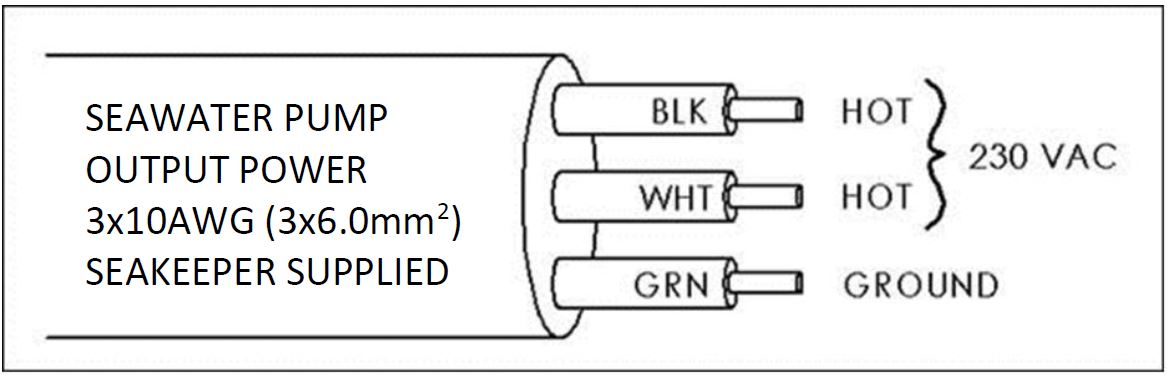
Figure 4 – Cable 5, AC Output Power Cable - Connect the 230 VAC wires in Cable 5 to a 5 A maximum, Seawater Pump (approximately 1/3 horsepower or 250 W) according to Figures 4 and 5.
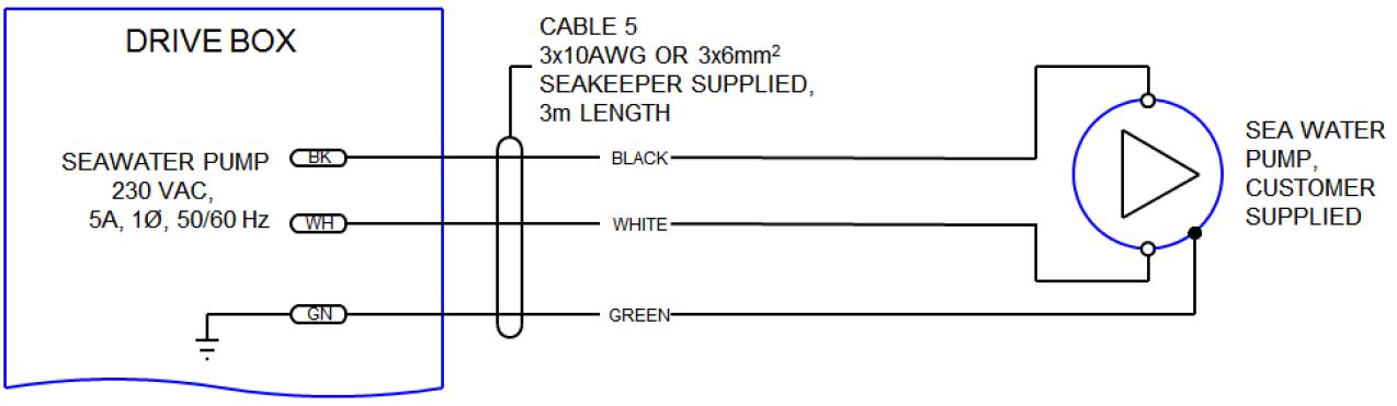
Figure 5 – Cable 5, Wire Connections to Seawater Pump
- Locate Cable 5, for AC power output to the Seawater Pump from the Drive Box at the middle of three cable glands. (See Figure 2.)
- If the customer-supplied Seawater Pump is not rated for 230 VAC, the Cable 5 output may be used to switch a customer-supplied relay.
- Locate Cable 5 for AC power output to the Seawater Pump from the Drive Box at the middle of three cable glands as shown in Figure 2.
- The recommended wiring is shown in Figure 6. Refer to Figure 4 for Cable 5 wire connections.
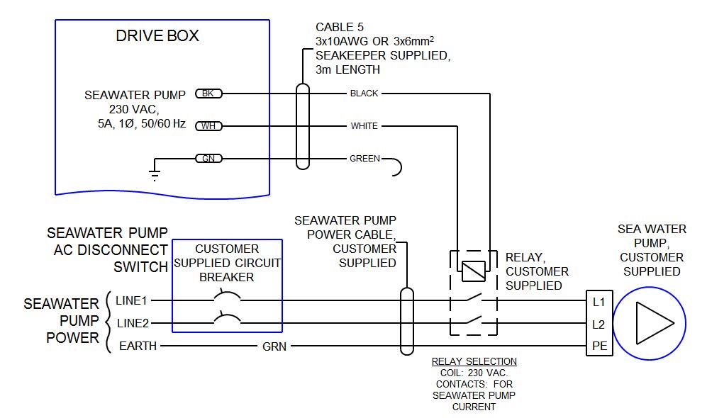
- If Cable 5 is not used, bundle cable and secure to Seakeeper frame or other area nearby which will not come in contact with moving parts during Seakeeper operation. Do NOT cut Cable 5 as it contains live voltage when Seakeeper is in operation. Seakeeper ships with Cable 5 permanently sealed at end of cable with protective cap in the event it is not used. Do NOT remove Cable 5 from Drive Box as moisture will be free to enter box through open cable gland and corrode internal electronic components
Cable 5 contains live voltage when Seakeeper is in operation. Do
NOT cut Cable 5. Do not remove Cable 5 from Drive Box.
24 VDC Power Source Requirements
- 24 VDC, 15 A
- A separate breaker should be used for each Seakeeper.
DC Power Connection Instructions
Reversing polarity on the DC power input to the Seakeeper can result in damaging the electronics in the control system.
- 24 VDC, 15 A, 2 x 12 AWG (3 x 4 mm2 CSA) Seakeeper supplied.
- Install Seakeeper provided DC Power Input Cable, P/N 20248, as Cable 1.
- Route Cable 1 to DC Power Distribution Panel.
- Terminate red conductor to +24 VDC. Terminate black conductor to 24 V Rtn or 0 VDC.
- Before connecting Cable 1 to Seakeeper, check for proper voltage and polarity with a DC multimeter using Figure 7 below.
- Connect Cable 1 to 24 VDC input receptacle on Seakeeper.
- Install Seakeeper provided DC Power Input Cable, P/N 20248, as Cable 1.
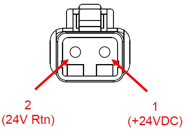
When energizing DC power for the first time, if Display does not power up immediately then disconnect and inspect connector polarity.