Seakeeper 26 Installation Manual (90265-8); S/N 26-233-0690 to Current
4.2 Connecting Seawater to Heat Exchanger
4.2.1 Installation Considerations
- Installer is responsible for supplying a dedicated seawater pump and associated plumbing. Seawater connections on the Seakeeper heat exchanger mate with ¾ in. (19 mm) hose.
- There is no need to disconnect hose from glycol pump except to replace the pump. In this case, provision will need to be made to catch draining glycol as plumbing is disconnected. Use caution to avoid breaking plastic hose connections on pump casing.
- An output is available from motor drive box to power and automatically control seawater pump (Cable 5). This pump must operate on 230 VAC single phase and consume less than 5 A. Pumps requiring other voltages or higher current can still be controlled by using this supply from motor drive to trigger an installer-supplied contactor, but a separate source of power must be provided.
- A dedicated through-hull fitting should be installed for each Seakeeper unit onboard the vessel to ensure sufficient seawater flow to each unit.
- Maximum seawater pressure in heat exchanger is 20 psi (1.4 bar).
- Seawater flow requirement through heat exchanger is 4 GPM (15.1 LPM) minimum and 8 GPM (30.3 LPM) maximum under all operating conditions of the boat. When sizing seawater pump, installer should factor in losses for raw water plumbing. In addition to initial operation at dock, new Seakeeper installations should be checked to be within the flow requirements while vessel is at speed. Flows higher than 8 GPM (30.3 LPM) could affect heat exchanger life.
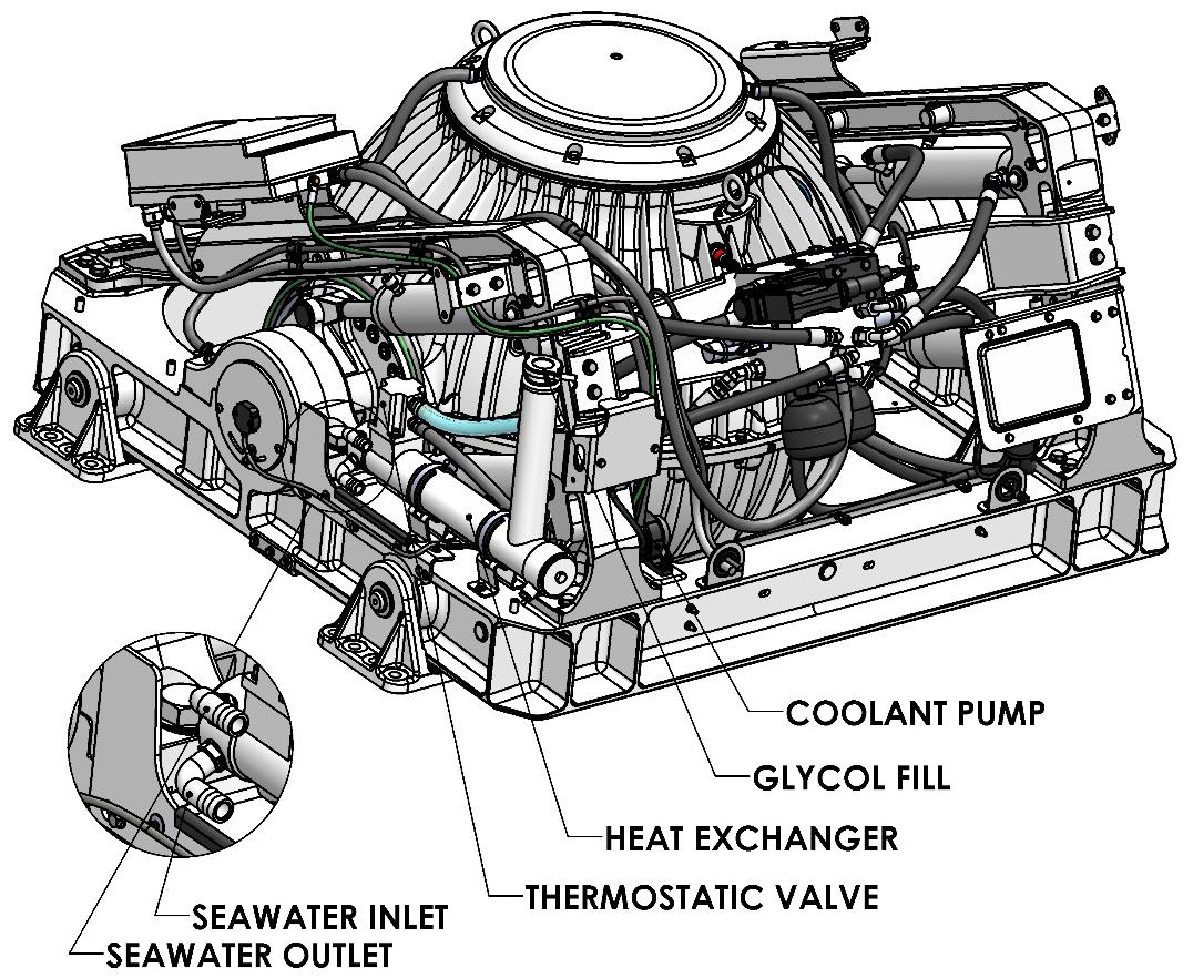
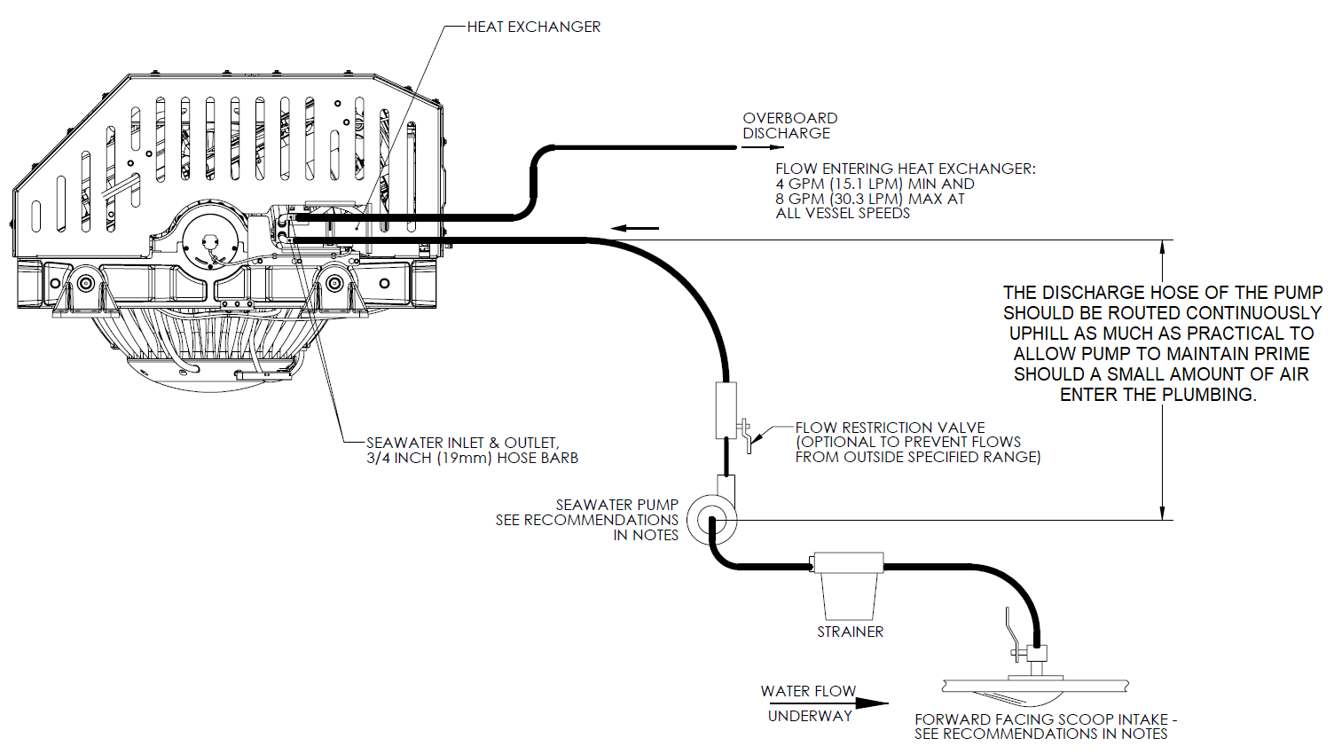
4.2.2 Connecting Seawater to Heat Exchanger
Refer to Figure 4 for typical seawater plumbing arrangement.
- Connect seawater pump to Seakeeper dedicated through-hull fitting. A strainer and seacock valve should generally be installed between the seawater inlet and the pump.
- Connect seawater from installer-supplied pump to lower ¾ in. (19 mm) hose barb on heat exchanger. Use the same practices as other below waterline seawater plumbing. Required flow rate is 4 GPM (15.1 LPM) minimum and 8 GPM (30.3 LPM) maximum. Refer to Figure 1, in Section: Cooling Installation – Introduction.
- Connect seawater discharge (upper hose barb) to overboard drain. Use the same practices as typical below waterline seawater plumbing.
- In addition to initial operation at dock, new installations should be checked with a flow meter for minimum 4 GPM (15.1 LPM) flow while vessel is at speed and when backing down.
- If no other method of confirming flow is available, discharge line may be temporarily diverted to a bucket. Flow is calculated from time to fill a known volume.
- A self-priming seawater pump (customer/installer supplied) may be required due to installation location to maintain water flow in all underway conditions where cavitation near the intake may occur and potentially cause an air-lock condition restricting seawater flow to the heat exchanger.
- Inspect raw water plumbing after sea trial for any signs of leakage.
- Heat exchanger contains removable end-caps to provide access for cleaning the tube bundle.