Seakeeper 16/18/12HD Installation Manual (90549-2)
Cooling Installation
Cooling Installation Introduction
The Seakeeper 16/18 is shipped with the cooling circuit filled and ready for use. Only a confirmation of glycol level is required.
Reference Documents & Drawings:
Link to Seakeeper 16/18 Reference Documents
- 90243 – Seakeeper 16 Hardware Scope of Supply
- 90538 – Seakeeper 18 Hardware Scope of Supply
- 90539 – Seakeeper 16/18 Cable Block Diagram
- 90540 – Seakeeper 16/18 Cooling Water Schematic
Precautions
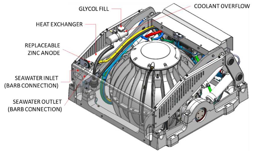
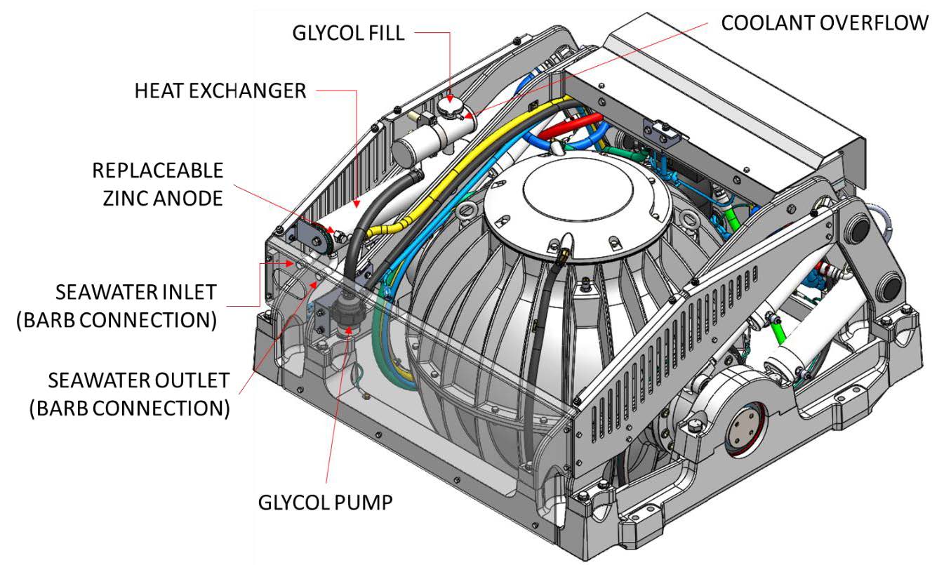
- Installer is responsible for supplying a dedicated seawater pump and associated plumbing. Seawater connections on the Seakeeper heat exchanger mate with ¾ in. (19 mm) hose. Seakeeper DC Seawater Pump, 24 VDC (P/N 30322) is available as an option from Seakeeper.
- There is no need to disconnect hose from glycol pump except to replace the pump. In this case, provision will need to be made to catch draining glycol as plumbing is disconnected. Use caution to avoid breaking plastic hose connections on pump casing.
- An output is available from wire harness ‘Seawater Pump-Out’ to power and automatically control seawater pump. This pump must operate on 24 VDC single-phase and consume less than 10 A. Pumps requiring other voltages or higher current can still be controlled by using this supply from motor drive to trigger an installer-supplied contactor, but a separate source of power must be provided.
- Maximum seawater pressure in heat exchanger is 30 psi (2.07 bar).
- Seawater flow requirement through heat exchanger is 4 GPM (15.1 LPM) minimum and 8 GPM (30.3 LPM) maximum under all operating conditions of the boat. When sizing sea water pump, installer should factor in losses for raw water plumbing. In addition to initial operation at dock, new installations should be checked to be within the flow requirements while vessel is at speed. Flows higher than 8 GPM (30.3 LPM) could affect heat exchanger life.
Adding Coolant
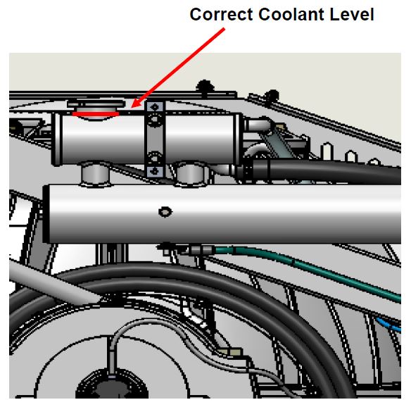
- Cooling system is filled to proper level when shipped, with a mixture of 50% ethylene glycol and 50% distilled water. Clear tube between thermostat housing and reservoir should be filled with green coolant mixture. If level has dropped, check for evidence of leaks at all connections before adding fluid as described below. If coolant is at the correct level, skip to Section: Connecting Seawater to Heat Exchanger.
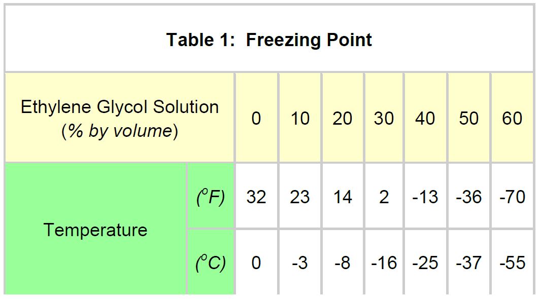
- Mix 50% ethylene glycol with 50% distilled water in a clean container. Refer to Table 1 or glycol manufacturer’s literature for freezing points.
- Remove pressure cap on top of reservoir. Pour mixture in until level reaches top of clear tube between thermostatic valve and reservoir as shown in Figure 3. Filling reservoir above this level will not cause any damage but coolant may be expelled from pressure relief port below cap due to normal thermal expansion of coolant.
- Connect 24 V to controller.
- At the Display check for any ALARMS
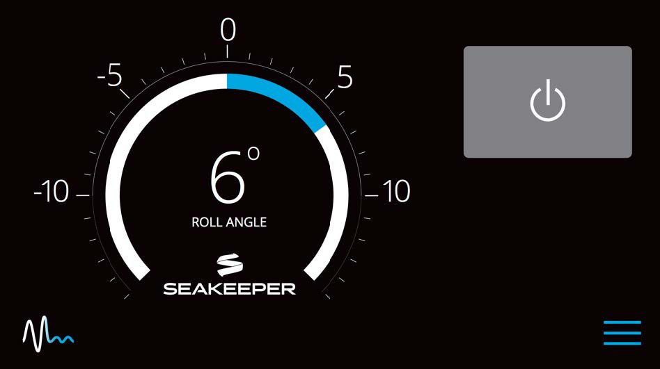
- Press the POWER ON/OFF button.

- The flywheel will start to spin and the glycol pump will start.
- Recheck glycol level with fluid circulating in coolant circuit. Sight down inside reservoir and check that coolant level is above upper port on reservoir as shown in Figure 3. Replace cap.
- After several minutes of running, press POWER ON/OFF button
 to turn power off to the flywheel and glycol pump. The glycol pump will stop, and the flywheel will coast to a stop.
 - Seawater cooling is not required when the Seakeeper is powered off and the flywheel is coasting to a stop.
- At the Display check for any ALARMS
- The cooling system is self-purging. If small amounts of air are in the system, they will most likely be dislodged during the first sea trial. Re-check level after sea trial and add fluid if required.
Connecting Seawater to Heat Exchanger
- Connect seawater from installer supplied pump to ¾ in. (19 mm) hose barb on heat exchanger. Use the same practices as typical below waterline seawater plumbing. Required flow rate is 4 GPM (15.1 LPM) minimum and 8 GPM (30.3 LPM) maximum.
- Connect seawater return to overboard drain. Use the same practices as typical below waterline seawater plumbing.
- In addition to initial operation at dock, new Seakeeper installations should be checked with a flow meter for minimum 4 GPM (15.1 LPM) flow while vessel is at speed and when backing down. If no other method of confirming flow is available, discharge line may be temporarily diverted to a bucket. Flow is calculated from time to fill a known volume. A self-priming sea water pump (customer/installer supplied) may be required due to installation location to maintain water flow in all underway conditions where cavitation near the intake may occur and potentially cause an air-lock condition restricting seawater flow to the heat exchanger.
- To prevent cavitation / aeration of the seawater intake a forward-facing scoop should be utilized. In addition, the seawater intake should be located in a location that will not aerate during normal underway operation.
- Inspect raw water plumbing after sea trial for any signs of leakage.
- Heat exchanger contains removable endcaps to provide access for cleaning the tube bundle.