Seakeeper 16/18/12HD Installation Manual (90549-2)
Mechanical Installation
Mechanical Installation Introduction
The Seakeeper 16/18 can produce vertical loads up to 5,965 lbs (26.5 kN), longitudinal loads up to 3,409 lbs (15.61 kN), and transvers loads of 500 lbs (2.22 kN) at each of the four mounts. Careful consideration should be given to foundation design to insure it is capable of transferring these loads into the hull. These loads do NOT include vessel motion accelerations, such as vertical slam loads which can be significant for high speed vessels and vary based upon the longitudinal location.
There are two methods of installing the Seakeeper 16/18:
1. Bolt-In Installation
2. Bond-In (Saddle) Installation
It is assumed that the installer is familiar with bonding using high strength adhesives or mechanical fasteners to marine structures and has performed structural analysis to assure the structure to which the Seakeeper mounts can properly transfer the loads the Seakeeper creates into the hull structure. If the installer has any doubt about the ability of the structure to transfer the loads to the hull, then a licensed naval architect or marine engineer should be contacted to do a structural analysis.
The installer should review the following list of reference drawings to ensure the installation procedure is fully understood.
Reference Documents & Drawings:
Link to Seakeeper 16/18 Reference Documents
- 90243 – Seakeeper 16 Hardware Scope of Supply
- 90538 – Seakeeper 18 Hardware Scope of Supply
- 90544 – Seakeeper 16/18 Bolt-In Installation Guide
- 90545 – Seakeeper 16/18 Bond-In Installation Guide
- 90540 – Seakeeper 16/18 Cooling Water Schematic
- 90282 – Seakeeper 16/18/12HD Installation Template Kit
- 90539 – Seakeeper 16/18 Cable Block Diagram
- 90548 – Seakeeper 16/18 Bolt-In Kit
- 90547 – Seakeeper 16/18 Bond-In Kit
Precautions
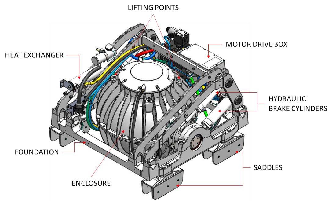
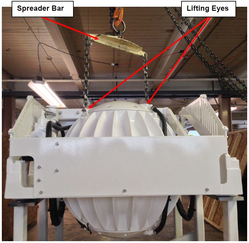
- The Seakeeper must only be lifted from the supplied lifting eyes shown in Figure 1 (see Section: Transport and Unpacking).
- The Seakeeper flywheel is supported by precision bearings. DO NOT drop or impart mechanical shock to the Seakeeper assembly while lifting or unpacking, as damage to bearings could result.
- While handling / installing the Seakeeper assembly, protect exposed hydraulic brake cylinder rods (See Figure 1) from scratches or damage as this could lead to premature seal failure and oil leaks.
- While handling / installing the Seakeeper assembly, do not allow electrical fittings that exit the bottom of the Seakeeper enclosure to come in contact with any surface or object as this could damage the fittings and potentially affect the vacuum integrity of the enclosure.
- Exercise care to protect the painted surfaces as damage to the finish could lead to early appearance degradation of the installed Seakeeper.
Selection of Installation Location
Selection of mounting location of the Seakeeper should consider the following desirable features:
The Seakeeper should be installed aft of amidships to minimize high acceleration loadings due to hull/wave impacts during operation at high speed or in large waves. If the only possible Seakeeper location is forward of amidships then the installer should have Seakeeper review the installation location prior to finalizing the design.
- Overhead access or sufficient clearance for removal / re-installation of the Seakeeper for overhaul in future years.
- The Seakeeper should be installed in a dry space to minimize effects of corrosion.
- Clearance for all recommended scheduled maintenance and any repairs is necessary (see Figure 2).
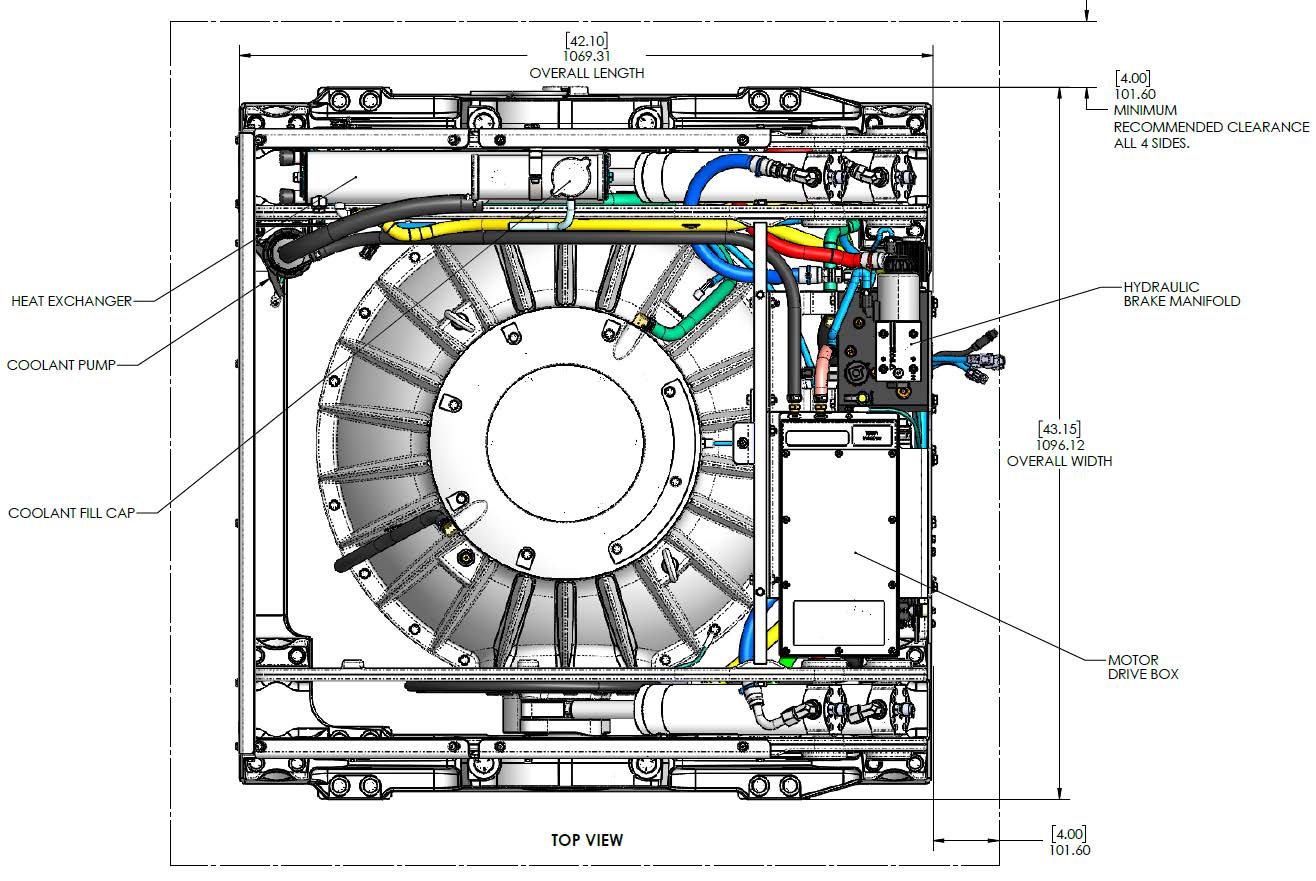
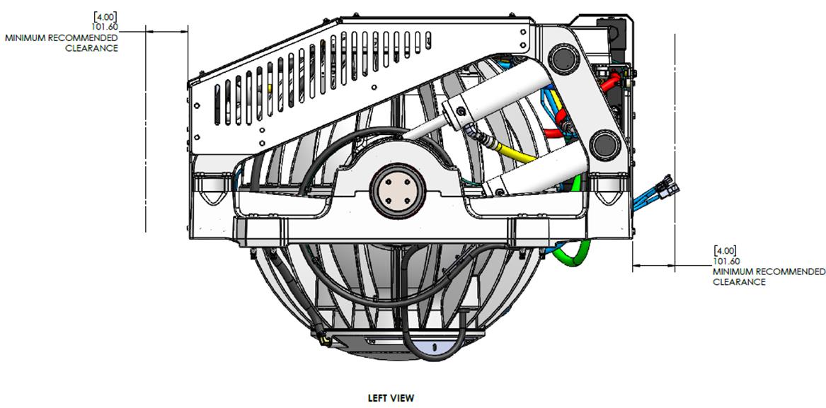
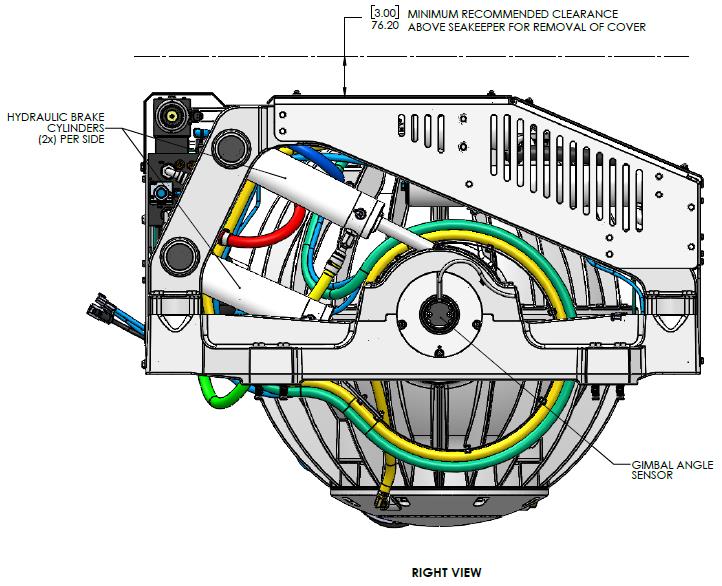
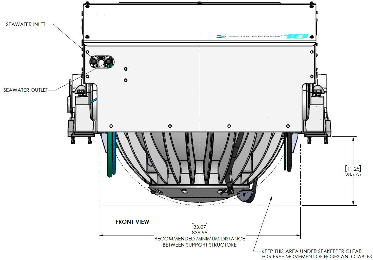
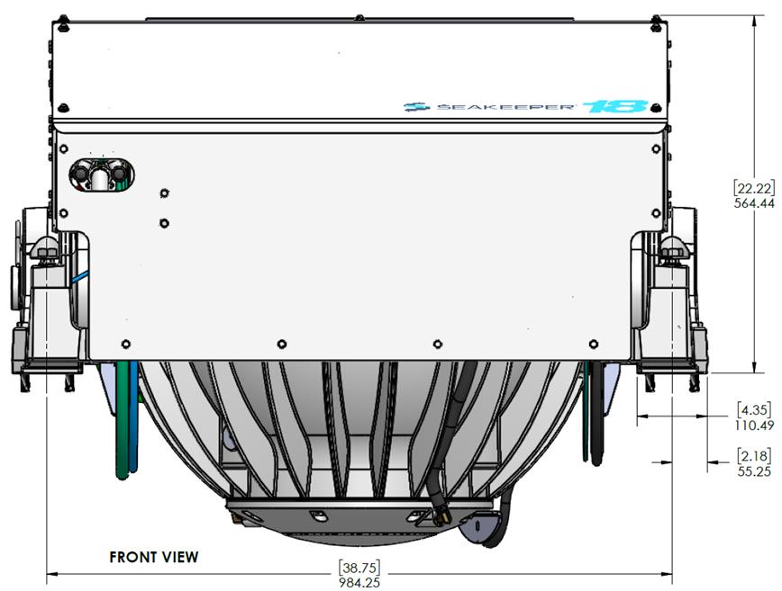
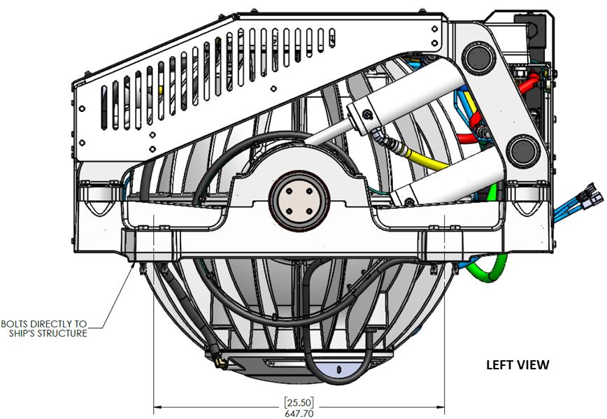
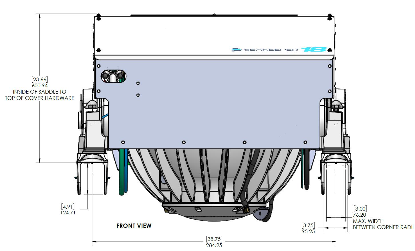
VIEWS SHOWING RECOMMENDED SERVICE CLEARANCES AROUND THE SEAKEEPER FOR USE OF HAND TOOLS, EASE OF MAINTENANCE, INSTALLATION AND PROPER OPERATION.
Figure 2 – Seakeeper 16/18 Installed Clearance Considerations
Refer to Figure 3 for required clearances to transverse beams. If a transverse beam is located under the forward brace, it must be 1 in. (25 mm) from the edge of the Seakeeper to provide the necessary clearance for the swing of the motor power cable during the Seakeeper’s precession. Clearances aft of the Seakeeper are shown to provide access for regular scheduled maintenance.
Safety

There is a large torque about the gimbal axis when the Seakeeper is precessing. Seakeeper cover panels are provided to prevent personnel or equipment from contacting the Seakeeper while it is in operation. These covers should not be stepped on, or have anything placed on top. The covers should always be in place during operation. If it is ever necessary to access the Seakeeper while the flywheel is spinning, the Seakeeper must be locked at the display to stop the Seakeeper from precessing. Seakeeper regular scheduled maintenance should only be performed by authorized personnel when the Seakeeper is locked and the flywheel is at 0 RPM.
The Seakeeper and related structure should be treated with the same respect one gives a high-speed rotating propeller or engine shaft.
Noise/Soundproofing
Seakeeper noise has been measured under steady state conditions (no wave load) in Seakeeper‘s lab and in our test boat. The steady state noise is typically in the range of 66-68 dB un-weighted. As the frequencies emitting the highest sound pressures are low (like other marine machinery), it is recommended that the Seakeeper be installed in an enclosed space such as a machinery space, lazarette, or bilge. If additional noise reduction is needed sound proofing insulation can be used in the space around the Seakeeper unit.
Selection of Installation Method
The Seakeeper 16/18 can be affixed to the hull structure using two methods:
1. Bolt-In Installation or
2. Bond-In (Saddle) Installation.
See figures below.
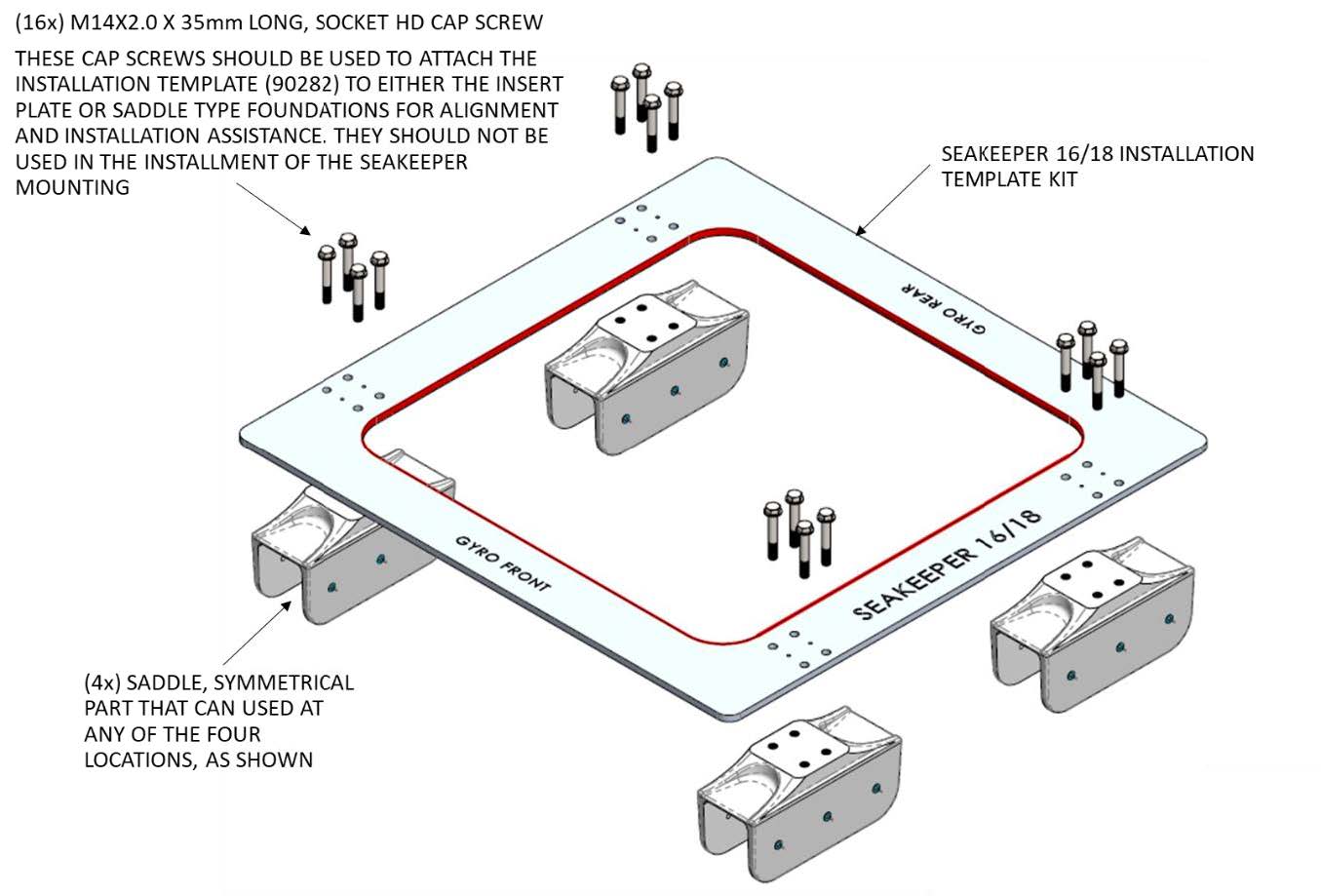
Option 1 would be applied when a metal structure or metal reinforce fiberglass stringer is available for attachment. The foundation would fasten directly to the hull structure using isolation gaskets for metal-to-metal contacts and (16) M14X2.0 fasteners. Depending on the structure to which the Seakeeper is fastened, blind threaded holes or thru-bolting can be utilized.
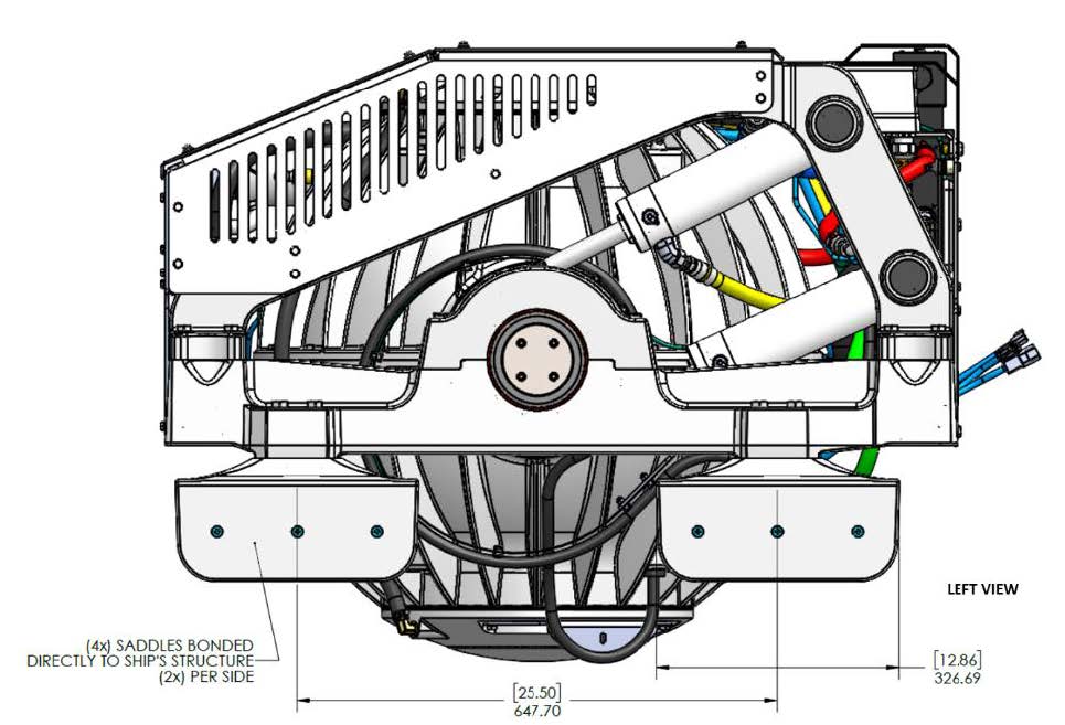
Option 2 would be most commonly used on a hull constructed of glass reinforced plastic (GRP) or fiberglass. For this option, four 12.9-in (327 mm) long x 4.9-in (125 mm) wide x 6.7-in (170 mm) height saddles are bonded to properly spaced and prepared structural members that are an integral part of the hull structure. Seakeeper recommends using a structural adhesive with a lap shear strength of 2000 psi (13.8 MPa) or greater. Careful consideration should be exercised by the installer while selecting the appropriate adhesive. Compatibility with the Seakeeper’s cast aluminum A356-T6 saddles, hull structure and pot life are three important factors to consider. Proper surface preparation in accordance with adhesive manufacturer’s recommendations prior to installation is very important. Recommended adhesives can be found in Seakeeper Technical Bulletin 90382 – Adhesive Recommendations.
Transport and Unpacking
Transport
- Use a Seakeeper provided shipping crate for transport. Overall dimensions of a fully packed crate are 52 L x 53 W x 47 H in. (1.32 L x 1.35 W x 1.19 H m) with a weight of 2,650 lbs (1,202 kg).
- Do not stack Seakeeper shipping crates.
- Both Air and Ground transport are acceptable.
- Seakeeper shipping crates must be transported in environmental conditions between -4°F and 140°F (-20°C and 60°C).
Unpacking Crate
- Reference Seakeeper Drawing No. 90243 – Seakeeper 16 Hardware Scope of Supply and Drawing No. 90538 – Seakeeper 18 Hardware Scope of Supply, for items that ship with the corresponding Seakeeper model.
- Remove electrical components, cables, and misc. items and set aside.
- Remove packing materials that secure Seakeeper assembly inside the crate.
- Remove top and angled face cover panels to access lifting eyes.
- Attach spreader bar (P/N 80061) to the two lifting eyes located on the top of the Seakeeper enclosure. Stay clear of any other parts on the Seakeeper. The Seakeeper weighs 2,270 lbs (1,030 kg). See Figure 4 below.
- Remove lag bolts from the Seakeeper foundation and prepare to lift the Seakeeper from the crate.
Bolt-In Installation
Check and Preparation of Hull Structure
Refer to Seakeeper Drawing No. 90544 – Seakeeper 16/18 Bolt-In Installation Details. Important dimensional and load information is given in this drawing that will impact the design details of the structure that will receive the Seakeeper. It is assumed that a proper structural analysis has been performed for the hull structure to which the Seakeeper will be fastened to ensure proper strength margins for the loads the Seakeeper will create during operation. Seakeeper recommends a safety factor of 3.0.
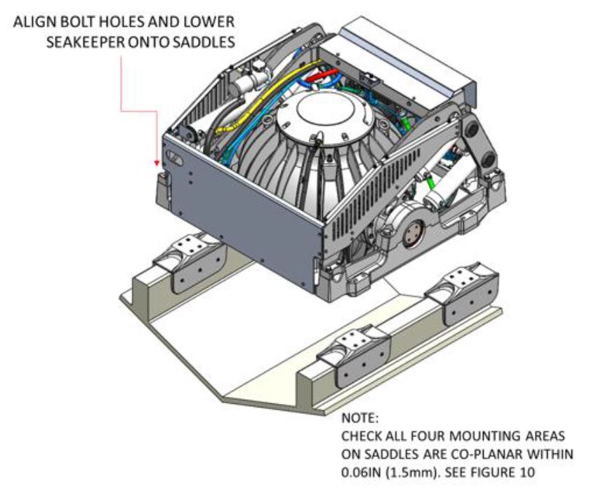
The hull structure supporting the Seakeeper should be arranged so the Seakeeper is parallel to the water plane in the port-starboard and forward-aft directions . In addition, the four areas on top of the beams on which the feet of the isolation mounts will rest, need to be co-planar within .06 in. (1.5 mm) to minimize potential distortion of Seakeeper support frame when installed. The isolation gaskets are only used on dissimilar metal to metal contact.
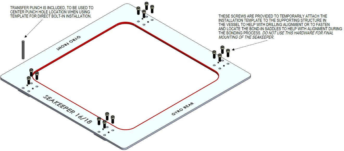
Seakeeper provides an installation fixture assembly (P/N 90282), which contains four plates that mimic the mating surfaces of the four isolation mounts located on the Seakeeper’s foundation. These plates have 4 holes located at the same centers as the mounting holes on the Seakeeper. The fixture locates the hole patterns at the proper spacing, both in the fore-aft direction and the port-starboard direction. See Figure 5 below. Once assembled, the fixture can be used to check clearances and alignment of the hull structure.
Note: Do NOT use the installation fixture to establish Seakeeper envelope dimensions. Refer to Drawing No. 90544 – Seakeeper 16/18 Bolt-In Installation Details, for envelope dimensions. A 3-D model of the Seakeeper is available on the Seakeeper website (www.seakeeper.com) to aid in designing the Seakeeper foundation and the space around the Seakeeper.
NOTE: MAKE SURE NO OBSTRUCTIONS FROM THE HULL STRUCTURE CAN BE SEEN WITHIN THE INSIDE OF THE INSTALLATION TEMPLATE KIT (INSIDE THE MARKED RED LINES). REFERENCE SEAKEEPER DRAWING NO. 90544 – SEAKEEPER 16/18 BOLT-IN INSTALLATION DETAILS.
CAUTION: Tight clearances from cable guide bands to hull structure. See above figure for dimensions and reference Seakeeper Drawing No. 90544 – Seakeeper 16/18 Bolt-In Installation Details, for complete envelope.
Transfer of Holes to Boat Structure
- Lower assembled fixture onto hull structure.
- The four areas where the feet of the Seakeeper will rest should be coplanar to within .06 in. (1.5 mm). See figure below.
- Align fixture in desired location and transfer holes from fixture plate to the hull structure. Note that holes in fixture plate are ø0.55 in. (14 mm).
- Remove fixture and drill and tap M14X2.0 holes in hull structure at marked locations to mate with holes in Seakeeper foundation. Take special care to drill perpendicular to mounting surface. Remove any impeding obstructions.
Installation of Seakeeper
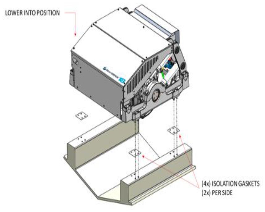
- Locate and position 4 isolation gaskets onto foundation beams (for metal to metal contacts only).
NOTE: Sealant or caulk is recommended to be applied. Apply a small bead (approximately 4 mm wide) of sealant (silicone or caulk) between both mating surfaces of each isolation gasket where it contacts the beam and the Seakeeper. This will prevent water from wicking between the parts and setting up corrosion. Check isolation gasket alignment by test fitting bolts without any obstructions. - Lower Seakeeper into position onto the hull foundation beams and align over drilled holes.
- Install Seakeeper-supplied M14 fasteners as shown in figure below – apply a moderate coat of marine anti-seize (e.g. SAF-T-EZE Nickel Grade Anti-Seize, SBT-4N or equivalent) to the threads of each bolt and include a small bead of sealant under each bolt head before installation.
- Torque all fasteners to 100 ft-lbs (136 N-m).
- Proceed to electrical and cooling portion of the installation.
Saddle Installation
Saddle Installation Introduction
Seakeeper recommends a slow curing, non-sagging structural adhesive for bonding the saddles to the GRP hull structure. Such an adhesive is Plexus MA590 which is a two-part methacrylate adhesive. Details of the bonding procedure in this manual will involve the Plexus MA590 product, but that should not exclude other suitable adhesives the installer chooses to use. See Sheet 5 of Seakeeper Drawing No. 90545 – Seakeeper 16/18 Bond-In Installation Details for loads information and recommended adhesive properties.
Check and Preparation of Hull Structure
Refer to Seakeeper Drawing No. 90545 – Seakeeper 16/18 Bond-In Installation Details. Important dimensional and load information is given in this drawing that will impact the design details of the structure that will receive the Seakeeper as well as selection of the adhesive to bond the Seakeeper into the hull.
The foundation “saddles” of the Seakeeper are designed to be bonded directly to the composite hull structure of the vessel to effectively distribute Seakeeper loads. A complete bond is required between the inside surface of the saddles and the hull structure. An estimate of adhesive volume required should be calculated for each installation based on gaps between saddles and structural members. There is some adhesive waste as a part of the process so a good rule of thumb is to purchase 50% more adhesive than estimated volume to ensure a complete bond. Depending on conditions and adhesive used, two workers may be required to apply the adhesive at the same time to finish the installation before the adhesive starts to cure. To aid in determining the quantity of adhesive required, the interior surface area (bonding surfaces) of each saddle is 164 in.2 (1,058 cm2) for a total bonded surface area for all four saddles of 656 in.2 (4,232 cm2).
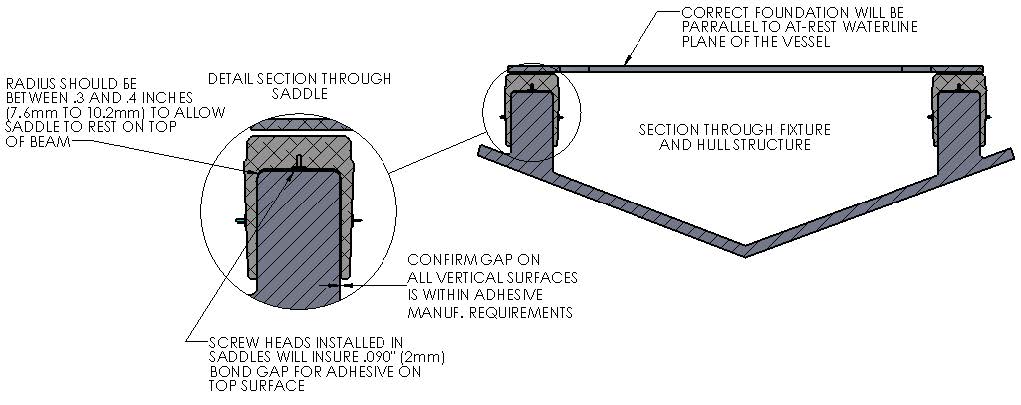
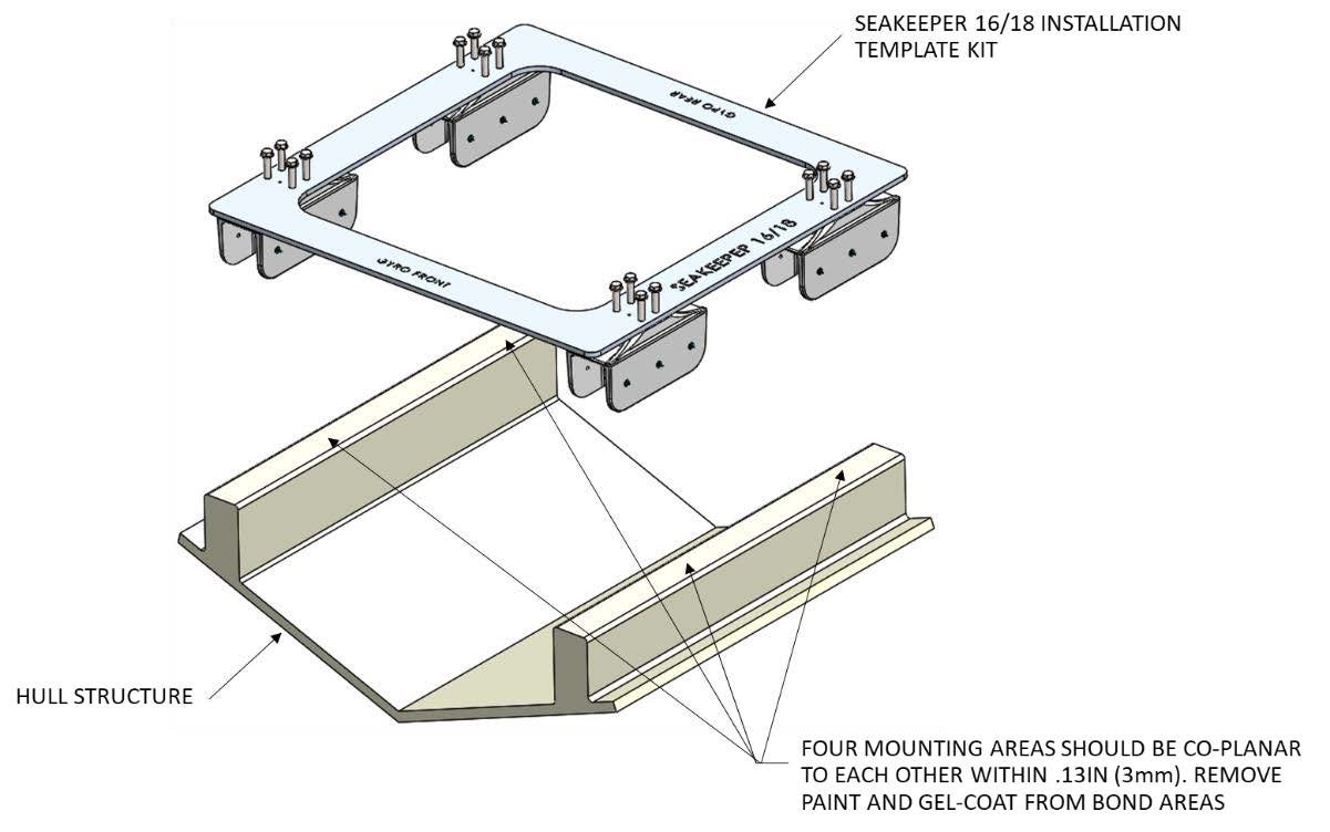
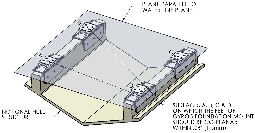
The hull structure supporting the Seakeeper should be arranged so the Seakeeper is parallel to the water plane in the port-starboard and forward-aft directions. The four areas on top of the beams that the saddles will bond to need to be co-planar within .13 in. (3 mm) for consistent adhesive bond gap. In addition, the four areas on top of the saddles on which the feet of the Seakeeper foundation will rest need to be co-planar within .06 in. (1.5 mm) to minimize potential distortion of Seakeeper support frame when installed.
Note that any paint or gel-coat present in bond area should be removed so that adhesive will bond directly to laminate fibers and resin.
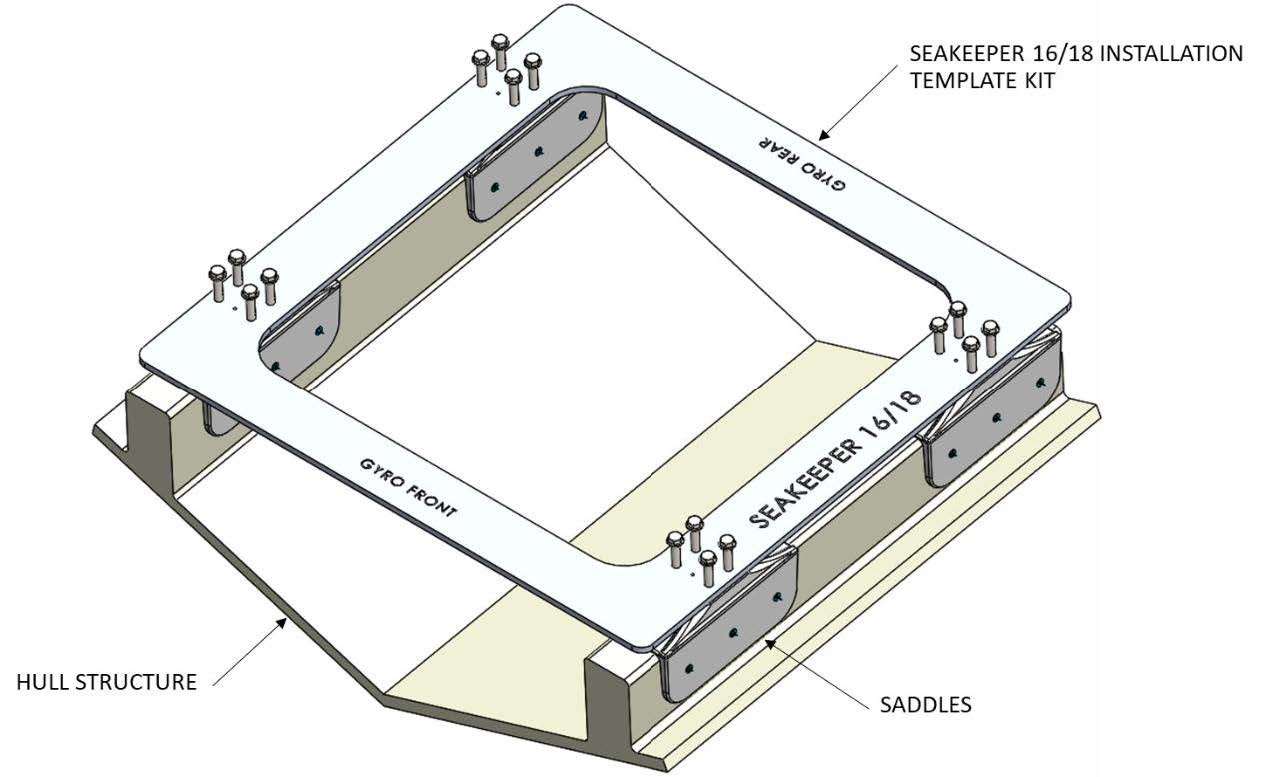
Seakeeper provides an installation fixture template (P/N 90282), that locates the saddles at the proper spacing both in the port-starboard and the forward-aft direction direction. See Figures 6 and 7 below. Once assembled with the provided saddle fittings, the fixture can be used to check clearances and alignment of the hull structure. The fixture will allow the builder / installer to lay-up and adjust the foundation dimensions to create a low-clearance fit between the Seakeeper foundation saddles and the hull structure. Shear strength of the adhesive will be maximized if the cured thickness between the vessel structure and the Seakeeper saddles is at the thinner end of the adhesive manufacturer’s recommended range. Therefore, the fixture should be used to confirm that the overall dimensions of the foundations are square and level and that the adhesive gap is within Seakeeper’s recommended range of .04 in. to .13 in. (1 to 3 mm).
Note: Do NOT use the installation fixture to establish Seakeeper envelope dimensions. Refer to Drawing No. 90545 – Seakeeper 16/18 Bond-In Installation Details, for envelope dimensions. A 3-D model of the Seakeeper is available on the Seakeeper website (www.seakeeper.com) to aid in designing the Seakeeper foundation and the space around the Seakeeper.
Fiberglass Hull Preparation
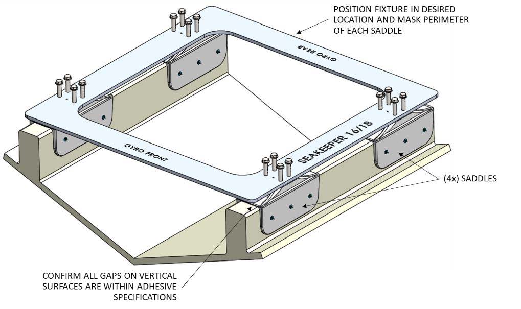
- Position installation fixture (Figure 8) on hull girders noting recommended clearances for maintenance from Figure 2 (in Section: Selection of Installation Location). Check that the screws fastening the saddles to the installation fixture are tight (Figure 6).
- Mask hull area (Figure 9) around foundation saddles for easy clean-up and to create an outline of surface area to receive adhesive as shown in Figure 8. Ensure that the bond gap is within adhesive manufacturer’s recommended thickness, or 3 mm if using Plexus MA590.
- Raise fixture clear of foundation. Check all four mounting areas are co-planar to within .13 in. (3 mm) to each other, as well as parallel to the water line plane, as shown in Figure 8.
- Remove any paint or gel-coat from bond surfaces so that adhesive will bond directly to laminate fibers and resin.
- Thoroughly sand girder bond surfaces with 80 grit sandpaper. (IMPORTANT – BOND STRENGTH MAY BE REDUCED IF THIS STEP IS SKIPPED.)
- Wipe surfaces clean from dust with alcohol or acetone using new paper towels, not shop rags.
- Re-position installation fixture on girders and double-check that the adhesive gap is within the adhesive manufacturer’s maximum recommended thickness. Seakeeper recommends a maximum gap of 3 mm if using Plexus MA590.
Note: If bonding saddles to a non-composite hull, contact Seakeeper for hull preparation instructions.
Seakeeper Saddle Preparation
- Ensure that screws fastening saddles to the installation fixture are tight (Figure 6).
- Check that each saddle contains 2 plastic screws which will ensure an adhesive gap of .080 in. (2 mm) on top surface of hull as shown in Figure 11.
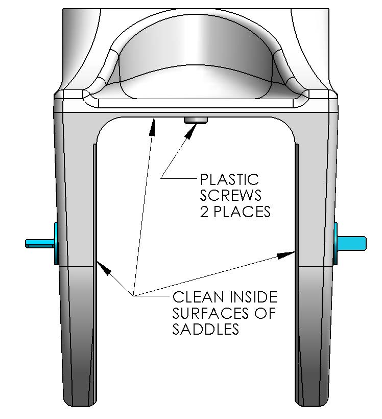
- Thoroughly sand all saddle inside surfaces with 80 grit sandpaper. (IMPORTANT – BOND STRENGTH MAY BE REDUCED IF THIS STEP IS SKIPPED.)
- Wipe surfaces clean from dust with alcohol or acetone using new paper towels, not shop rags.
- If using Plexus MA590 adhesive, apply Plexus PC-120 surface conditioner to inside surfaces of Seakeeper foundation saddles in accordance with manufacturer instructions. These instructions are located at the end of this section. If using an alternate adhesive, check with manufacturer if any surface conditioner/etch is required for the aluminum saddles.
Bonding Saddles to Hull
Note: This is a sample if using Plexus, if using another adhesive follow manufacturer’s recommendations.
If using Plexus MA590 adhesive, the Seakeeper saddles should be installed when PC-120 is confirmed dry.
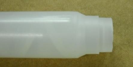
- Assemble Plexus cartridge into either the manual or pneumatic gun as shown. Remove cap on cartridge and attach mixing tip. For pneumatic gun, start with low air pressure and increase until desired flow rate is achieved.
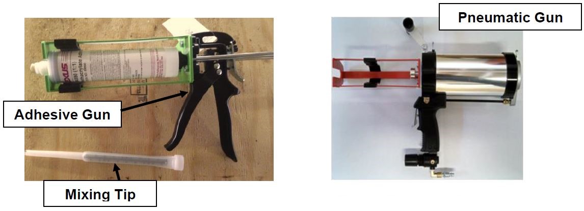
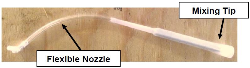
- Cut tip of mixing wand as shown in photo below.
- Prepare a second mixing wand as shown in photo below by attaching the simple flexible nozzle to the end of the mixing tip. Set aside for now as this will be used to inject adhesive into the sides of each saddle after the fixture / saddles are in position.
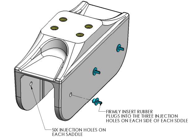
- Install provided rubber plugs in six holes of each saddle. The plugs will limit the adhesive being forced out of the injection holes in step 6 below.
- Apply large bead of Plexus adhesive to the hull structure as shown in the figure below. Apply approximately 2/3rds to 1 cartridge at each of the four locations. Work deliberate and fast as it takes some time to apply the adhesive to the structure. MA590 has a 90-minute working time at room temperature (73°F / 23°C). This working time can reduce to 40-50 minutes at elevated temperatures. Two workers should apply the adhesive at the same time to finish the installation before the adhesive starts to cure.
- Lower fixture and saddles over the hull structure and apply light downward pressure to each of the four saddles until the two nylon screws rest on the hull structure (see Figure 7). The adhesive will be forced towards the forward and aft ends of each saddle and partially down the sides of the foundation beams.
- Insert full adhesive cartridge along with mixing wand / nozzle assembled in Step 3 above, into gun.
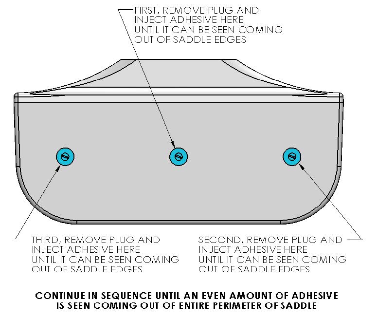
- Begin to inject adhesive into the six holes provided on each side of each of the four saddles. Follow the numbered sequence shown until the adhesive pushes out the edges of the saddle perimeter. The intent is to pump in the adhesive working from the top down and from the middle to the ends to fill the gaps and displace any air. A complete bond is required – excess adhesive will be needed to make sure all bond gaps are filled.
- Repeat above step for remaining 7 sides of the saddles.
- When gaps have been completely filled, clean off excess adhesive, remove plugs, and remove masking tape.
- Allow adhesive to cure per manufacturer’s recommendations. Follow adhesive guidelines for curing time versus temperature prior to removing the fixture.
- Bonding of Seakeeper saddles onto the hull is now complete. Remove installation fixture.
Installation of Seakeeper
- The four areas where the feet of the Seakeeper will rest should be co-planar to within .06 in.
- Rig the Seakeeper for lifting and lower it into position onto top surface of four saddles.
- Apply a small bead (approximately 4 mm wide) of sealant or caulk to the mating surfaces between the saddles and the Seakeeper foundation. Adjust position of the Seakeeper until alignment is achieved for the 16 fasteners that will attach Seakeeper foundation frame to saddles.
- Install Seakeeper supplied M14 fasteners – apply a moderate coat of marine anti-seize (e.g., SAF-T-EZE Nickel Grade Anti-Seize, SBT-4N or equivalent) to the threads of each bolt and include a small bead of sealant under each bolt head before installation.
- Torque all fasteners to 100 ft-lbs (136 N-m).
- Proceed to electrical and cooling portion of the installation.
Removal and Disposal
Removal
This section details basic instructions for removal of a Seakeeper from a boat. The overall basic instructions are to reverse the installation instructions:
- Disconnect seawater pump from heat exchanger and power connector on wiring harness.
- Drain heat exchanger of all seawater.
- Disconnect Seakeeper input power cables.
- Remove all installation fasteners.
- Remove the Seakeeper unit using a spreader bar.
Disposal
DO NOT disassemble the Seakeeper to a greater degree than necessary for removal from the boat. DO NOT dispose of a Seakeeper unit in a landfill. The unit must be shipped back to Seakeeper.
Plexus PC-120 Application Instructions
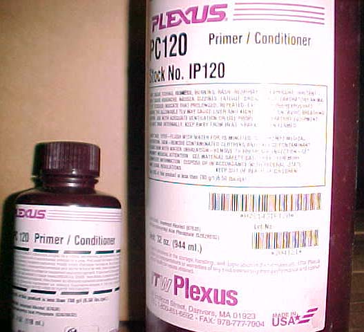
What is Plexus PC-120?
- Plexus PC‐120 is a dual function primer/conditioner designed to clean surface contamination and leave a thin coating of primer on specific metal surfaces.
- Although designed specifically for cleaning and priming of Aluminum and Stainless Steel, PC‐120 can be used to clean other surfaces in special situations. Contact Plexus Technical Service for recommendations on any surface other than Aluminum or Stainless Steel.
Plexus PC-120 works by:
- Cleaning the surface of contamination using Isopropyl Alcohol to “lift” machine oils and other contamination.
- Depositing a thin Phosphate based coating to retard corrosion.
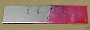
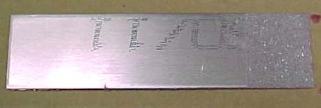
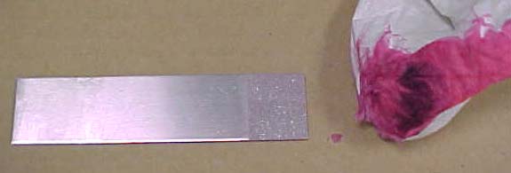
- Leaving a light “pink” color to assist in determining what areas have, and have not, been treated with PC‐120.
How should PC-120 be used?
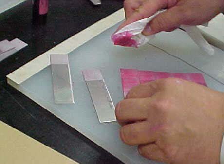
- PC‐120 can be brushed, wiped or sprayed onto the surface being primed.
- The PC‐120 applied should then be wiped with a clean dry rag to remove any surface contamination cleaned by the PC‐120 and leave only a thin, quick drying film.
- Dirty or oily rags should be replaced to avoid improper cleaning.
- Quality dye‐free paper towels that don’t leave fibers behind are recommended.
Common Mistakes with PC-120
- Using too much PC-120
- Only a very thin coat should be left on the metal. You should be able to see a slight “pink” cast as illustrated below.
- Not removing oils once primed
- The solvents in PC‐120 will clean and “lift” most machining oils, but if the metal isn’t wiped clean of these oils then they will be deposited right back onto the metal surface when the solvent in PC‐120 evaporates!
- While still wet, wipe the PC‐120 applied to the surface with a clean dry paper towel, changing the paper towel as needed.
- Not abrading corroded surfaces
- As good as PC‐120 is, it can’t help bonding performance if applied to a surface that is already corroded!
- Any surface that shows signs of corrosion should be cleaned by sanding or wire brushing to remove any scale or corrosion.
- After removal of corrosion then treat the surface with PC‐120 as you normally would.
- Using PC-120 past its shelf life
- When stored under normal conditions PC‐120 has a shelf life of 12 months in an unopened, original container.
- PC‐120 bottles are marked with a lot number that is a simple 8 digit code that gives you the date of manufacture.
- “807241” for example is 2008, 07 month (July), 24th day (the “1” refers to the first batch of PC‐120 made that day). Use the lot number to make sure the material is still within shelf life.
- Since it contains isopropyl alcohol, PC‐120 should be tightly capped when not in use to stop evaporation.
Remember these points to avoid problems with Plexus PC-120
- Don’t use too much PC‐120. Only a thin layer is needed.
- Use a clean rag to wipe PC‐120 off before it completely dries to remove surface contaminants it has cleaned. Good quality paper towels are a better choice to minimize introduction of contaminates to surface.
- Any sign of corrosion already on the surface should be removed by abrading BEFORE priming.
- Check the lot number for the date to make sure the PC‐120 is less than a year old.
Questions?
Please contact Plexus Technical Service at 1‐800‐851‐6692 or info@itwplexus.com