Seakeeper 16/18/12HD Installation Manual (90549-2)
Operator Station
This section explains the connection between the Operator Station equipment and the Seakeeper.
Reference Documents & Drawings
- 90539 – Seakeeper 16/18 Cable Block Diagram
Determine Location of Operator Station
- The desired location of the Operator Station must be determined with respect to the vessel arrangement.
- The operator display should be located on the bridge console.
- Figure 8 below shows the CAN bus communications link for the Operator Station. The Terminator goes on the far end of the Tee Adapter from the Seakeeper.
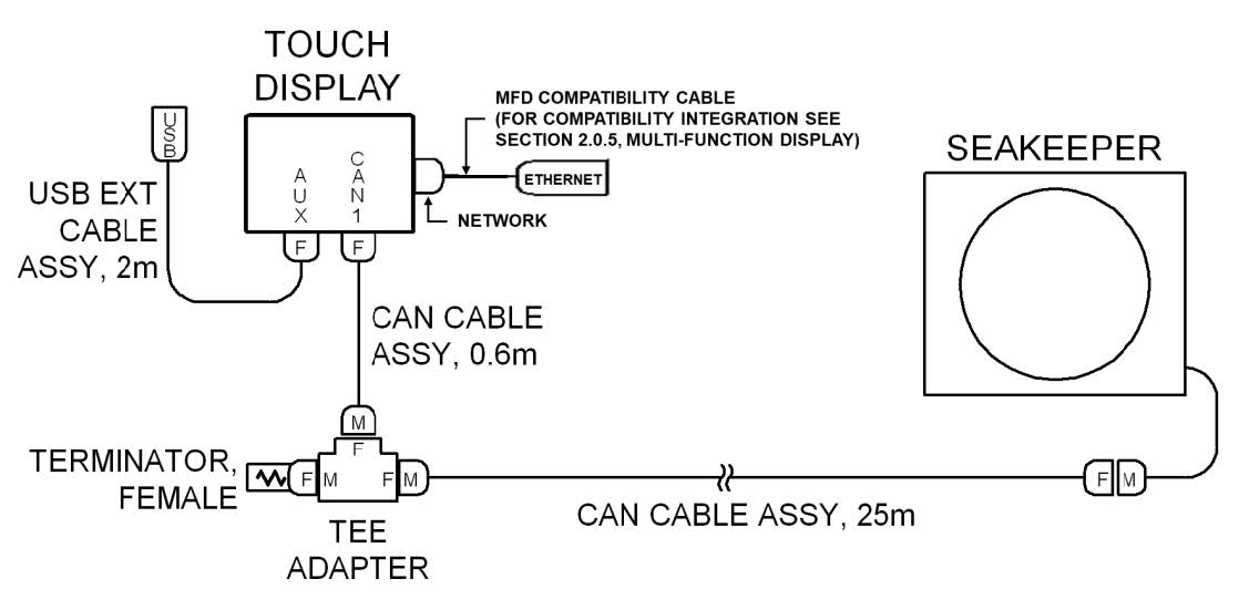
Route Serial Communications Cable
- The CAN Cable Assembly (P/N 30243, Cable 3) is a 25 m shielded cable and the largest connector is a molded plug with maximum outer diameter of .58 in. (14.8 mm).
- Cable 3 must be routed and installed in the vessel from the Seakeeper (female end) to the Tee Adapter (male end) at the Operator Station.
Install Operator Station Equipment
- The Operator Station equipment is installed at the selected location using instructions found in Section: Electrical Equipment Mounting.
Connect Operator Station Equipment
- The Operator Station equipment is connected in accordance with Drawing No. 90539 – Seakeeper 16/18 Cable Block Diagram.