Seakeeper 16/18/12HD Installation Manual (90549-2)
Bolt-In Installation
Check and Preparation of Hull Structure
Refer to Seakeeper Drawing No. 90544 – Seakeeper 16/18 Bolt-In Installation Details. Important dimensional and load information is given in this drawing that will impact the design details of the structure that will receive the Seakeeper. It is assumed that a proper structural analysis has been performed for the hull structure to which the Seakeeper will be fastened to ensure proper strength margins for the loads the Seakeeper will create during operation. Seakeeper recommends a safety factor of 3.0.
The hull structure supporting the Seakeeper should be arranged so the Seakeeper is parallel to the water plane in the port-starboard and forward-aft directions . In addition, the four areas on top of the beams on which the feet of the isolation mounts will rest, need to be co-planar within .06 in. (1.5 mm) to minimize potential distortion of Seakeeper support frame when installed. The isolation gaskets are only used on dissimilar metal to metal contact.
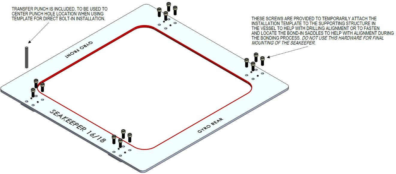
Seakeeper provides an installation fixture assembly (P/N 90282), which contains four plates that mimic the mating surfaces of the four isolation mounts located on the Seakeeper’s foundation. These plates have 4 holes located at the same centers as the mounting holes on the Seakeeper. The fixture locates the hole patterns at the proper spacing, both in the fore-aft direction and the port-starboard direction. See Figure 5 below. Once assembled, the fixture can be used to check clearances and alignment of the hull structure.
Note: Do NOT use the installation fixture to establish Seakeeper envelope dimensions. Refer to Drawing No. 90544 – Seakeeper 16/18 Bolt-In Installation Details, for envelope dimensions. A 3-D model of the Seakeeper is available on the Seakeeper website (www.seakeeper.com) to aid in designing the Seakeeper foundation and the space around the Seakeeper.
NOTE: MAKE SURE NO OBSTRUCTIONS FROM THE HULL STRUCTURE CAN BE SEEN WITHIN THE INSIDE OF THE INSTALLATION TEMPLATE KIT (INSIDE THE MARKED RED LINES). REFERENCE SEAKEEPER DRAWING NO. 90544 – SEAKEEPER 16/18 BOLT-IN INSTALLATION DETAILS.
CAUTION: Tight clearances from cable guide bands to hull structure. See above figure for dimensions and reference Seakeeper Drawing No. 90544 – Seakeeper 16/18 Bolt-In Installation Details, for complete envelope.
Transfer of Holes to Boat Structure
- Lower assembled fixture onto hull structure.
- The four areas where the feet of the Seakeeper will rest should be coplanar to within .06 in. (1.5 mm). See figure below.
- Align fixture in desired location and transfer holes from fixture plate to the hull structure. Note that holes in fixture plate are ø0.55 in. (14 mm).
- Remove fixture and drill and tap M14X2.0 holes in hull structure at marked locations to mate with holes in Seakeeper foundation. Take special care to drill perpendicular to mounting surface. Remove any impeding obstructions.
Installation of Seakeeper
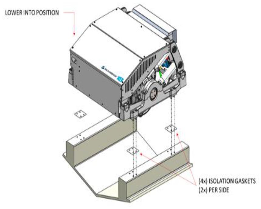
- Locate and position 4 isolation gaskets onto foundation beams (for metal to metal contacts only).
NOTE: Sealant or caulk is recommended to be applied. Apply a small bead (approximately 4 mm wide) of sealant (silicone or caulk) between both mating surfaces of each isolation gasket where it contacts the beam and the Seakeeper. This will prevent water from wicking between the parts and setting up corrosion. Check isolation gasket alignment by test fitting bolts without any obstructions. - Lower Seakeeper into position onto the hull foundation beams and align over drilled holes.
- Install Seakeeper-supplied M14 fasteners as shown in figure below – apply a moderate coat of marine anti-seize (e.g. SAF-T-EZE Nickel Grade Anti-Seize, SBT-4N or equivalent) to the threads of each bolt and include a small bead of sealant under each bolt head before installation.
- Torque all fasteners to 100 ft-lbs (136 N-m).
- Proceed to electrical and cooling portion of the installation.