Seakeeper 9 Installation Manual (90222-10); S/N 9-212-3388 to 9-234-4899
2.5 Bond-In Installation
2.5.1 Bond-In Installation Introduction
Seakeeper recommended adhesives are listed in TB-90382 – Structural Adhesives Recommendations. Seakeeper recommends using a structural adhesive with a lap shear strength of 2000 psi (13.8 MPa) or greater. Careful consideration should be exercised by the installer when selecting the appropriate adhesive, such as working time, material compatibility, and surface preparation are three important factors to consider. Proper surface preparation in accordance with the adhesive manufacturer’s recommendations prior to installation is critically important. Information regarding pot-life, structural properties and material compatibility can be found on the adhesive product’s technical data sheet (TDS). An etching/cleaning primer compatible with the adhesive should be used on all aluminum surfaces if recommended by the manufacturer. Typically, two-part methacrylate based adhesives are the best options for bond-in installations such as Plexus MA590 and Sci-GripSG300, which provide compatibility with aluminum and FRP substrates, adequate working time, and exceed the strength requirements. See Sheet 6 of Seakeeper Drawing No. 90226 – Seakeeper 9 Bond-In Installation Details for loads information and recommended adhesive properties.
2.5.2 Preparation of Hull Structure
Refer to Seakeeper Drawing No. 90226 – Seakeeper 9 Bond-In Installation Details. Important dimensional and load information is given in this drawing that will impact the design details of the structure that will receive the Seakeeper as well as selection of the adhesive to bond the Seakeeper into the hull.
The foundation “saddles” of the Seakeeper are designed to be bonded directly to the composite hull structure of the vessel to effectively distribute Seakeeper loads. A complete bond is required between the inside surface of the saddles and the hull structure. Seakeeper recommends having a minimum of 2.5 L / 0.66 gal of adhesive, on hand for installation. Number of cartridges required is determined by dividing total volume by cartridge volume. There is some adhesive waste as a part of the process so a good rule of thumb is to purchase 50% more adhesive than estimated volume to bond. Depending on conditions and adhesive used, two workers may be required to apply the adhesive at the same time to finish the installation before the adhesive starts to cure. To aid in determining the quantity of adhesive required, the interior surface area (bonding surfaces) of each saddle is 106 in.2 (684 cm2) for a total bonded surface area for all four saddles of 424 in.2 (2,736 cm2).
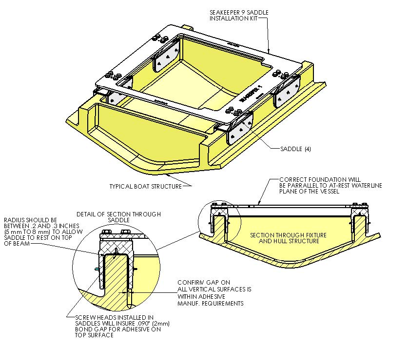
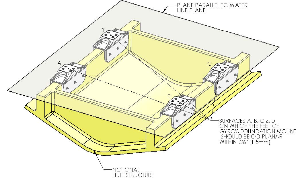
The hull structure supporting the Seakeeper should be installed so the Seakeeper is parallel to the waterline in the transverse direction and within 2 degrees longitudinally. The four areas on top of the beams that the saddles will bond to need to be co-planar within .13 in. (3 mm) for consistent adhesive bond gap. In addition, the four areas on top of the saddles on which the feet of the Seakeeper foundation will rest need to be co-planar within .06 in. (1.5 mm) to minimize potential distortion of Seakeeper support frame when installed.
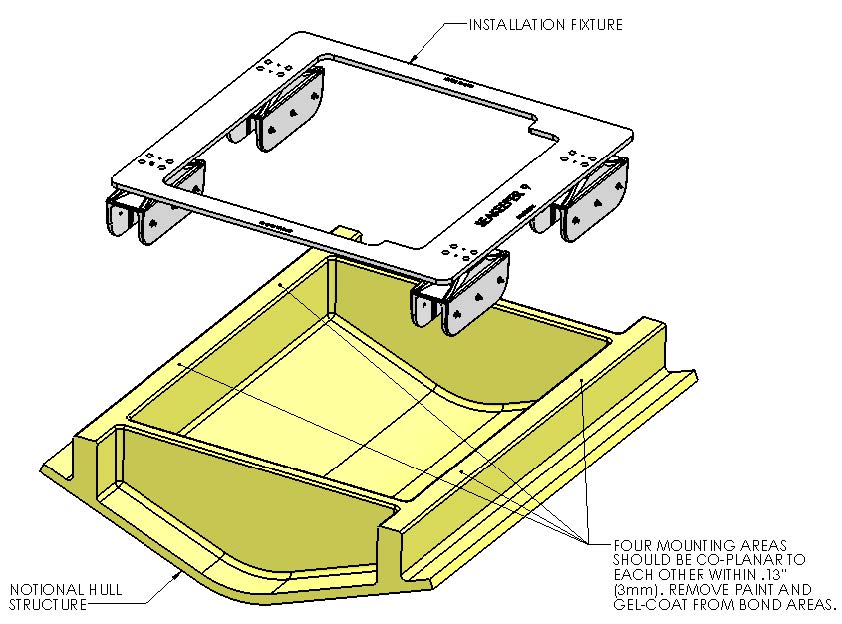
Note that any paint or gel-coat present in bond area should be removed so that adhesive will bond directly to laminate fibers and resin.
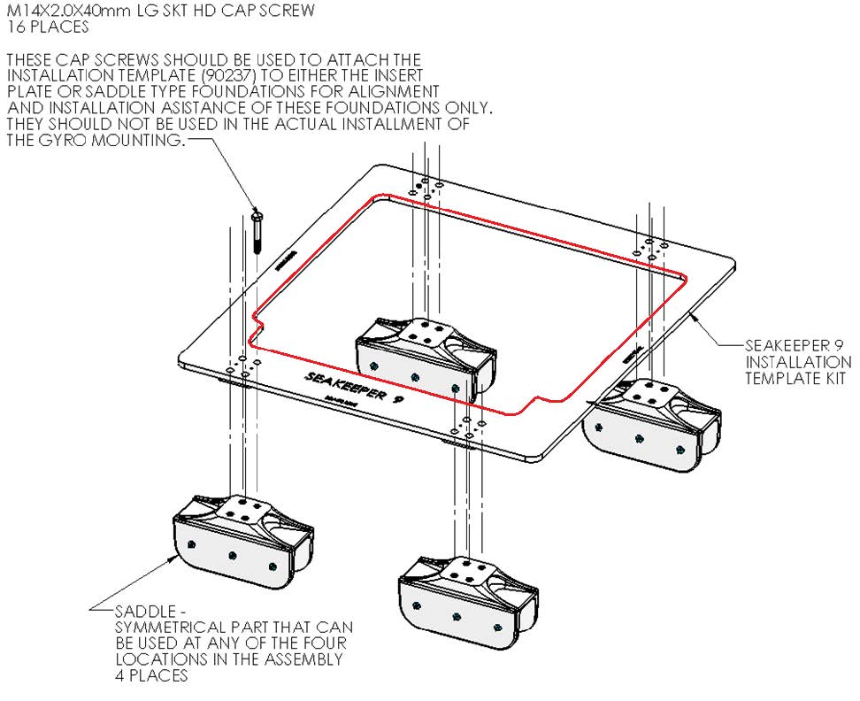
Seakeeper provides an installation fixture template, P/N 90253, that locates the saddles at the proper spacing both in the forward-aft direction and the port-starboard direction. See Figures 6 & 7 below, and Figure 8 in the following section. Once assembled with the provided saddle fittings, the fixture can be used to check clearances and alignment of the hull structure. The fixture will allow the builder / installer to lay-up and adjust the foundation dimensions to create a low-clearance fit between the Seakeeper foundation saddles and the hull structure. Shear strength of the adhesive will be maximized if the cured thickness between the vessel structure and the Seakeeper saddles is at the thinner end of the adhesive manufacturer’s recommended range. Therefore, the fixture should be used to confirm that the overall dimensions of the foundations are square and level and that the adhesive gap is within Seakeeper’s recommended range of .04 in. to .13 in. (1 to 3 mm).
Note: Do NOT use the installation fixture to establish Seakeeper envelope dimensions. Refer to Drawing No. 90226 – Seakeeper 9 Bond-In Installation Details, for envelope dimensions. A 3-D model of the Seakeeper is available on the Seakeeper Technical Library (http://www.seakeeper.com/technical-library/) to aid in designing the Seakeeper foundation and the space around the Seakeeper.
NOTE: MAKE SURE NO OBSTRUCTIONS FROM THE HULL STRUCTURE CAN BE SEEN WITHIN THE INSIDE OF THE INSTALLATION TEMPLATE KIT (INSIDE THE MARKED RED LINES). SEE DRAWING NO. 90226 – SEAKEEPER 9 BOND-IN INSTALLATION DETAILS.
2.5.3 Hull Preparation
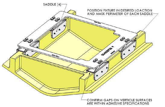
- Position installation fixture (Figure 8) on hull girders noting recommended clearances for maintenance from Figure 2 (in Section: Selection of Installation Location). Check that the screws fastening the saddles to the installation fixture are tight (Figure 6).
- Mask hull area (Figure 9) around foundation saddles for easy clean-up and to create outline of surface area to receive adhesive as (Figure 8). Ensure that the bond gap is within Seakeeper’s recommended thickness, or 3 mm if using Plexus MA590.
- Raise fixture clear of foundation. Check all four mounting areas are co-planar to within .13 in. (3 mm) to each other, as well as parallel to the water line plane, as shown in Figure 8.
- Thoroughly clean with alcohol or acetone all areas of girders to be bonded to remove any contaminates. Use new paper towels for cleaning, not shop rags.
- Remove any paint or gel-coat from bond surfaces so that adhesive will bond directly to laminate fibers and resin as shown in Figure 8.
- Thoroughly sand girder bond surfaces with 80 grit sandpaper. (IMPORTANT – BOND STRENGTH MAY BE REDUCED IF THIS STEP IS SKIPPED.)
- Wipe surfaces clean from dust with alcohol or acetone using new paper towels, not shop rags.
- Re-position installation fixture on girders and double-check that the adhesive gap is within the adhesive manufacturer’s maximum recommended thickness. Seakeeper recommends a maximum gap of 3 mm if using Plexus MA590.
Note: if bonding saddles to a metal structure, follow adhesive manufacturer instructions for metal substrates.
2.5.4 Seakeeper Saddle Preparation
- Ensure that screws fastening saddles to the installation fixture are tight (Figure 6).
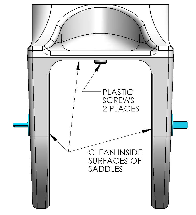
- Check that each saddle contains 2 plastic screws which will ensure an adhesive gap of .080 in. (2 mm) on top surface of hull as shown in Figure 11. Do not remove these screws.
- Thoroughly sand all saddle inside surfaces with 80 grit sandpaper in cross-hatch pattern. (IMPORTANT – BOND STRENGTH MAY BE REDUCED IF THIS STEP IS SKIPPED.)
- Thoroughly clean with alcohol or acetone the inside surfaces of Seakeeper foundation saddles to remove any contaminates as shown in Figure 11. Use new paper towels for cleaning, not shop rags.
- If using Plexus MA590 adhesive, apply Plexus PC-120 surface conditioner to inside surfaces of Seakeeper foundation saddles in accordance with manufacturer instructions. These instructions are located at the end of this section. If using an alternate adhesive, check with manufacturer if any surface conditioner/etch is required for the aluminum saddles.
2.5.5 Bonding Saddles to Hull
Note: This is a sample if using Plexus, if using another adhesive follow manufacturer’s recommendations.
If using Plexus MA590 adhesive, the Seakeeper saddles should be installed when PC-120 is confirmed dry.
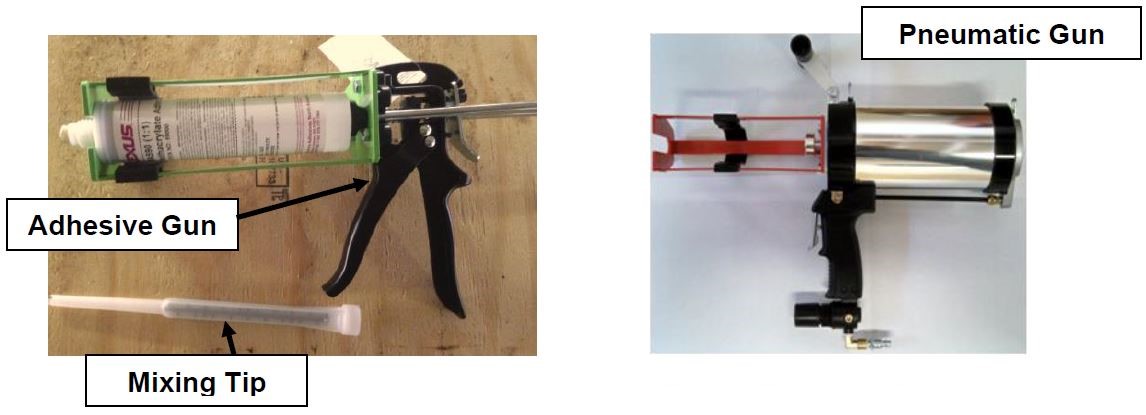
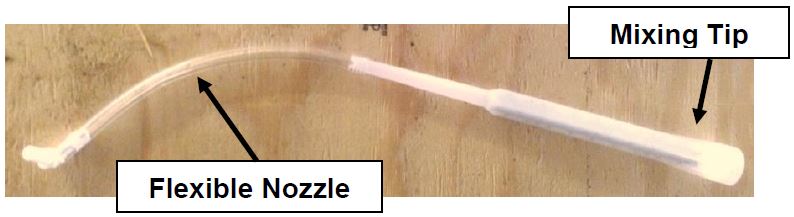
- Assemble Plexus cartridge into either the manual or pneumatic gun as shown. Remove cap on cartridge and attach mixing tip. For pneumatic gun, start with low air pressure and increase until desired flow rate is achieved.
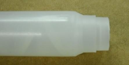
- Cut tip of mixing wand as shown in photo below.
- Prepare a second mixing wand as shown in photo below by attaching the simple flexible nozzle to the end of the mixing tip. Set aside for now as this will be used to inject adhesive into the sides of each saddle after the fixture / saddles are in position.
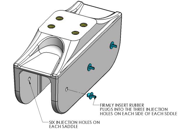
- Install provided rubber plugs in six holes of each saddle. The plugs will limit the adhesive being forced out of the injection holes in step 6 below.
- Apply large bead of Plexus adhesive to the hull structure as shown in the figure to the right. Apply approximately ½ to ⅔ cartridges (200 – 275 mL) at each of the four locations. Work deliberate and fast as it takes some time to apply the adhesive to the structure. MA590 has a 90-minute working time at room temperature (73°F / 23°C). This working time can reduce to 40-50 minutes at elevated temperatures. Two workers should apply the adhesive at the same time to finish the installation before the adhesive starts to cure.
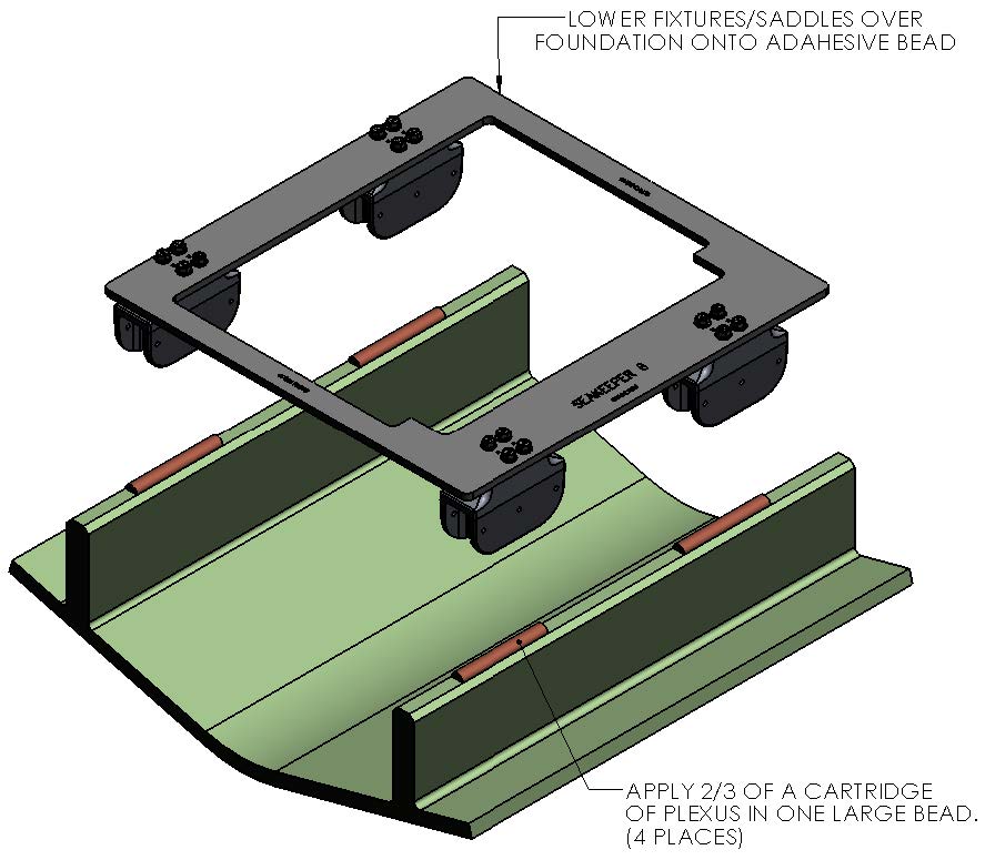
- Lower fixture and saddles over the hull structure and apply light downward pressure to each of the four saddles until the two nylon screws rest on the hull structure (see Figure 7). The adhesive will be forced towards the forward and aft ends of each saddle and partially down the sides of the foundation beams.
- Insert full adhesive cartridge along with mixing wand / nozzle assembled in Step 3 above into gun.
- Begin to inject adhesive into the six holes provided on each side of each of the four saddles. Follow the numbered sequence shown until the adhesive pushes out the edges of the saddle perimeter. The intent is to pump in the adhesive working from the top down and from the middle to the ends to fill the gaps and displace any air.
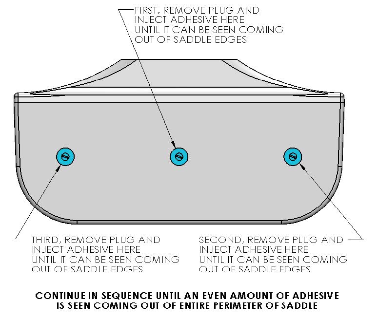
A complete bond is required – excess adhesive will be needed to make sure all bond gaps are filled.
- Repeat above step for remaining 7 sides of the saddles.
- When gaps have been completely filled, clean off excess adhesive, remove plugs, and remove masking tape.
- Allow adhesive to cure per manufacturer’s recommendations. Follow adhesive guidelines for curing time versus temperature prior to removing the fixture.
- Bonding of Seakeeper saddles onto the hull is now complete. Remove installation fixture.
2.5.6 Installation of Seakeeper
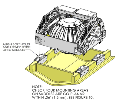
- The four areas where the feet of the Seakeeper will rest should be coplanar to within .06 in. (1.5 mm). See figure to the right.
- Rig Seakeeper for lifting and lower it into position onto top surface of four saddles.
- Apply a small bead (approximately 4 mm wide) of sealant or caulk to the mating surfaces between the saddles and the Seakeeper foundation. Adjust position of Seakeeper until alignment is achieved for the 16 fasteners that will attach the Seakeeper foundation frame to saddles.
- Install Seakeeper supplied Grade 8.8, M14-2.0 x 85 mm fasteners or alternative Grade M10.9, M14-2.0 bolts to maintain a minimum thread engagement of .084 in. (21 mm). Apply a moderate coat of nickel-based anti-seize (e.g., SAF-T-EZE nickel grade anti-seize, SBT-4N or equivalent) to the threads of each bolt and include a small bead of marine grade sealant (e.g., SILI-THANE 803 or equivalent) under each bolt head and washer before installation.
- Torque all fasteners to 100 ft-lbs (136 N-m).
- New bolts, matching the Seakeeper specification, must be used for each installation and reinstallation that meet the requirements listed above.
- Proceed to electrical and cooling portion of the installation.
3.0 Electrical Installation
3.1 Electrical Installation Introduction
This section for electrical installation explains how to mount the electrical equipment and how to connect the electrical cables.
Reference Documents & Drawings:
- 90221 – Seakeeper 9 Hardware Scope of Supply
- 90223 – Seakeeper 9 Operation Manual
- 90467 – 2nd Helm Control Station Kit
- 90257 – Seakeeper 9 Cable Block Diagram
- 90438 – Touchscreen Display Envelope and Mounting Details
- MFD Compatibility Technical Bulletins
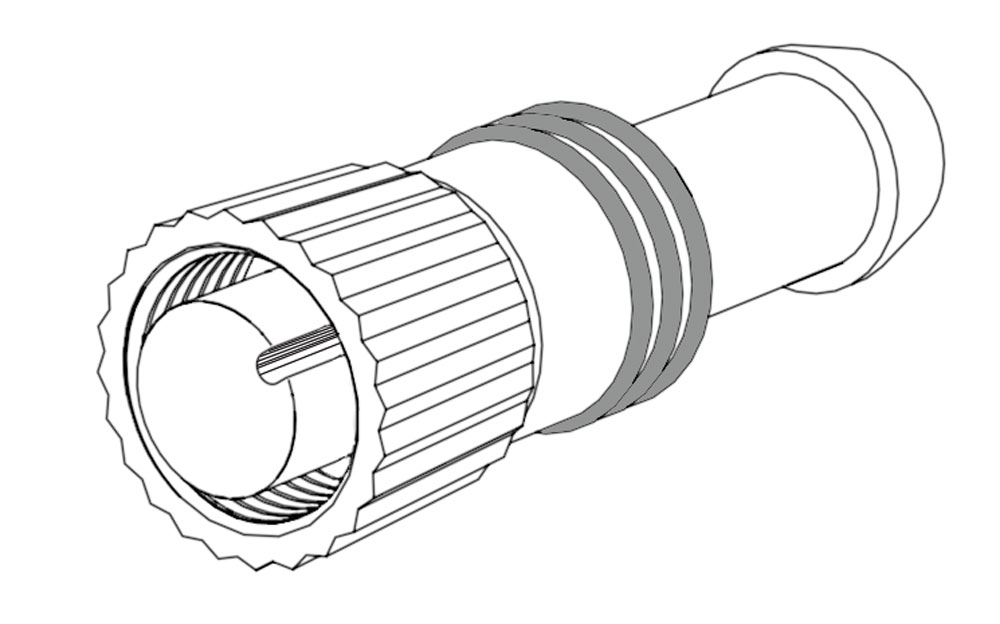
24 VDC Power Input Cable
P/N 20248
P/N 30249
P/N 30244
P/N 30298
USB Extension Cable
P/N 30300
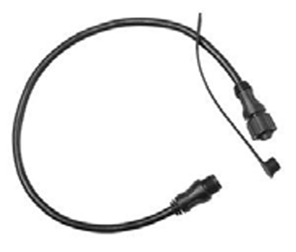
2 ft. Cable
P/N 30301
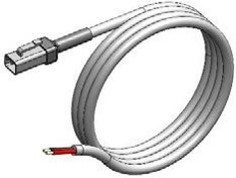
DC SW Pump Input
P/N 30327
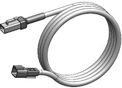
DC SW Pump Output
P/N 30327
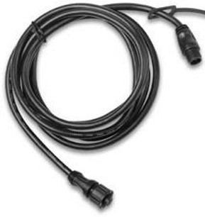
25 m Cable
P/N 30243
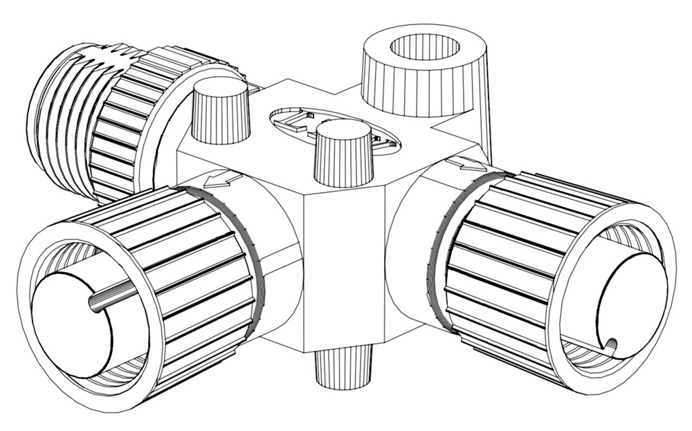
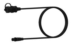
Figure 1 – Electrical Equipment for Seakeeper 9
3.2 Electrical Equipment Power Connections
3.2.1 230 VAC Power Source Requirements
- 230 VAC (nominal), 1 Phase, 50/60 Hz, 20 A
- For installations of more than one Seakeeper, a separate circuit breaker should be used for each Seakeeper Motor Drive Box.
3.2.2 Drive Box AC Power Input Connection Instructions
- Cable 2: 3 x 10 AWG (3 x 6 mm2 CSA), 10 ft. (3 m) length, Seakeeper supplied pre-installed.
- Locate Cable 2 for AC power input to the Drive Box at the outward of three cable glands.
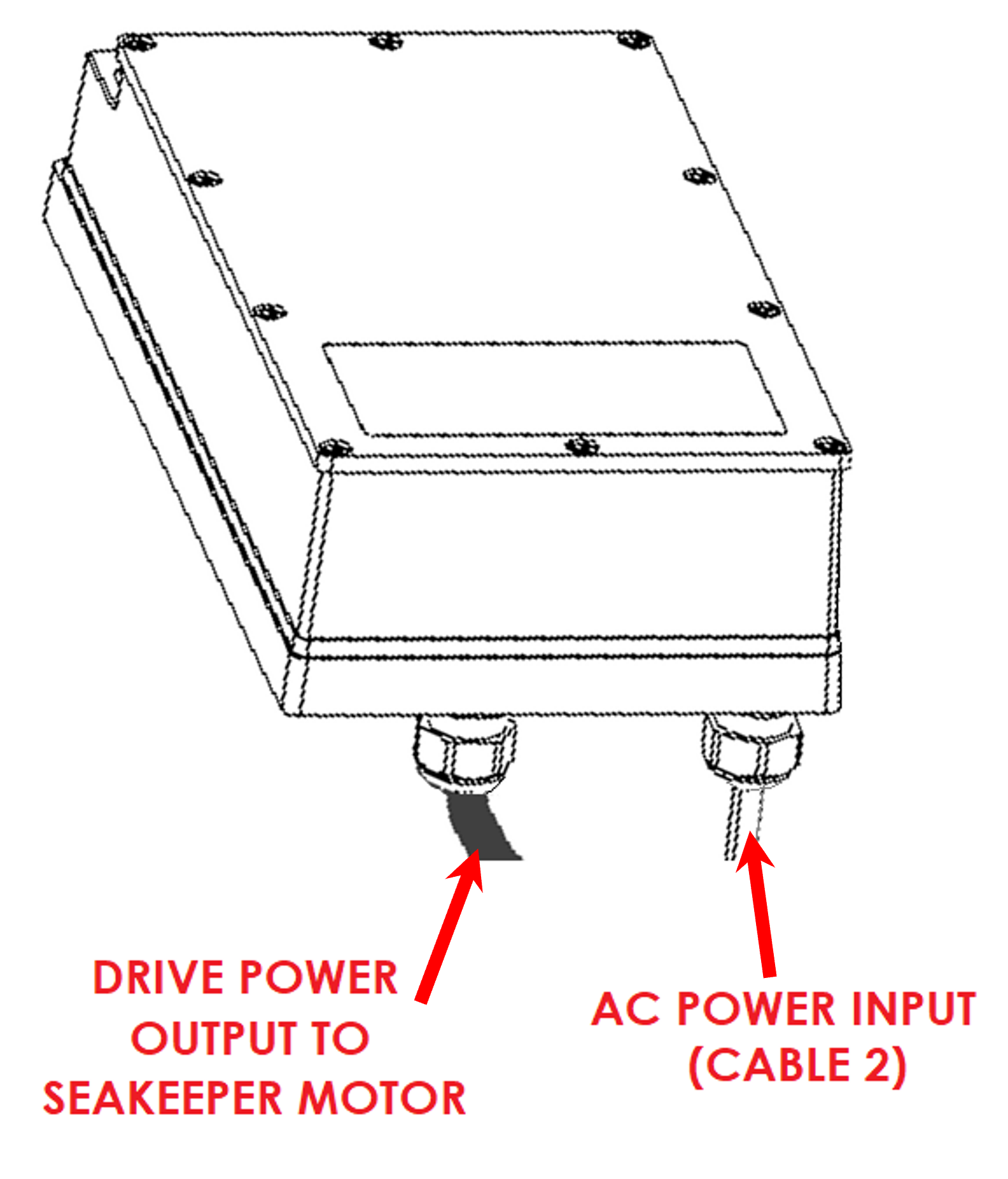
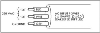
- Connect 230 VAC wires in Cable 2 to a 20 A, double-pole Circuit Breaker at an AC power distribution panel according to Figure 3 above.
3.2.3 24 VDC Power Source Requirements
- One 24 VDC, 10 A (Customer supplied) for Seakeeper Control Power, AND
- One 24 VDC, 10 A (Customer supplied) for DC Seawater Pump.
- A separate breaker should be used for each Seakeeper.
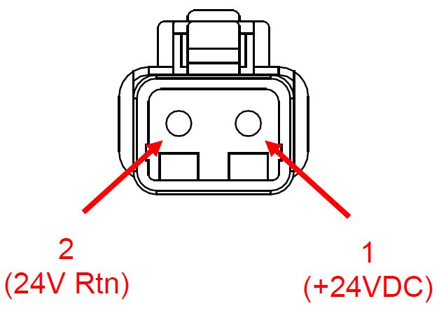
3.2.4 DC Power Connection Instructions
Reversing polarity on the DC power input to the Seakeeper can result in damaging the electronics in the control system.
- 24 VDC, 10 A, 2 x 12 AWG (3 x 4.0 mm2 CSA) customer supplied.
- Install Seakeeper provided DC Power Input Cable, P/N 20248 as Cable 1 (as shown in Drawing No. 90257).
- Route Cable 1 to DC Power Distribution Panel.
- Terminate positive (B+, Red ) conductor to +24 VDC.
- Terminate negative (B-, Black) conductor directly to battery negative terminal.
- Before connecting Cable 1 to Seakeeper, check for proper voltage and polarity with a DC multimeter using Figure 7 below.
- Connect Cable 1 to 24 VDC input receptacle on Seakeeper.
- Install Seakeeper provided DC Power Input Cable, P/N 20248 as Cable 1 (as shown in Drawing No. 90257).
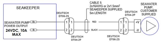
3.2.5 DC Seawater Pump 24 VDC Power Input Connection Instructions

Connecting the DC Seawater pump in any other manner than recommended by Seakeeper may cause internal failure.
- Install Cable 8 (P/N 30327) to Seakeeper 9 “SW Pump DC In” (as shown in Drawing No. 90257) with overcurrent protection corresponding to seawater pump selected.
- Connect the 16AWG positive conductor (Red) through dedicated overcurrent protection device (customer supplied), maximum of 10 A, to dedicated battery isolation switch.
- Connect the 16 AWG negative conductor (Black) directly to battery negative terminal or DC main negative bus bar.
- Before connecting Cable 8 to Seakeeper, check for proper voltage and polarity with a DC multimeter using Figure 8 below.
- Connect Cable 8 to Seawater Pump 24 VDC In connector on the Seakeeper, DEUTSCH DT04-2P connector.
3.2.6 DC Seawater Pump 24 VDC Power Output Connection Instructions
- Connect Cable 5 to the Seakeeper 9 “SW Pump 24VDC Out” for DC power to the seawater pump.
- Cable 5 is a 2 x 16 AWG cable, 16 ft (5m) length with a size 16 female Deutsch plug.
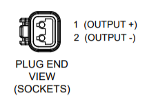
- Pumps rated at 24 VDC, 10 A maximum, customer-supplied, must be configured with a Deutsch DT series, 2-pin receptacle to mate with the connector shown in Figure 9.
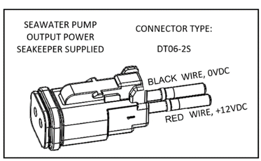
- Cable 5 must be routed and installed in the vessel from the Seakeeper 9 “SW Pump 24VDC Out” Deutsch connector (pins end) to the DC seawater pump cable Deutsch connector (socket end).
- Connect Cable 5 plug end (socket end) to the customer-supplied receptacle end (pins end). The recommended wiring is shown in Figure 10.
- Contact Seakeeper if desired to install customer-supplied relay on Cable 5 to power seawater pump.
3.3 Electrical Equipment Ground Connections
3.3.1 Seakeeper to Vessel Ground Connection Instructions
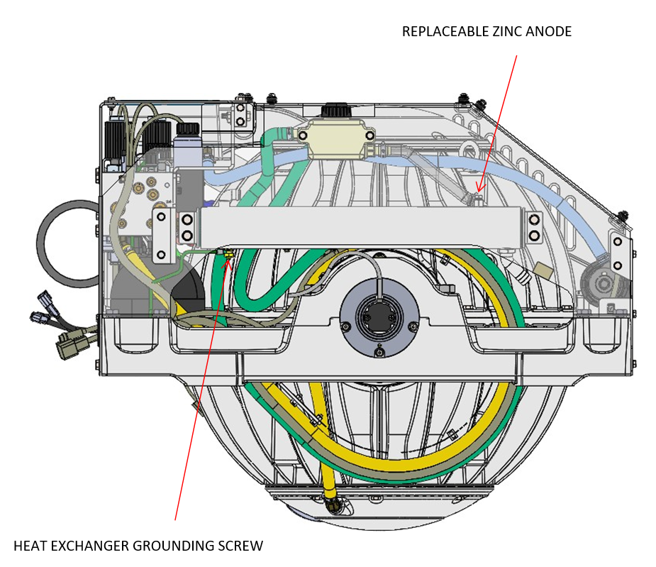
- Connect the Seakeeper foundation to vessel ground, as shown in Figure 8.
- Install Cable 6 (10 AWG or 6 mm2, Customer supplied) from the M6 brass ground stud on the Seakeeper rear brace to a suitable vessel ground.
- EN/IEC 90204-1 Clauses 6.3.3 and 8.2.3
- ABYC E-11 July 2018 Clauses 11.5.2 and 11.16.1.
- Ground connection should be made with vessel bonding system, if available. However, the ground is not referring specifically to a bonding system but for outboard boats generally refers to the outboard engine negative terminal. Per ABYC E-11 (2018), Clause 11.5.2.7.4: If the negative side of the DC system is to be connected to the ground, the connection shall be made only from the engine negative terminal, or its bus, to the DC grounding bus. This connection shall be used only as a means of maintaining the negative side of the circuit at ground potential and is not to carry current under normal operating conditions.
- A proper ground connection is critically important for corrosion protection and helps to ensure the ignition protection of the unit by ensuring it does not carry any stray current.
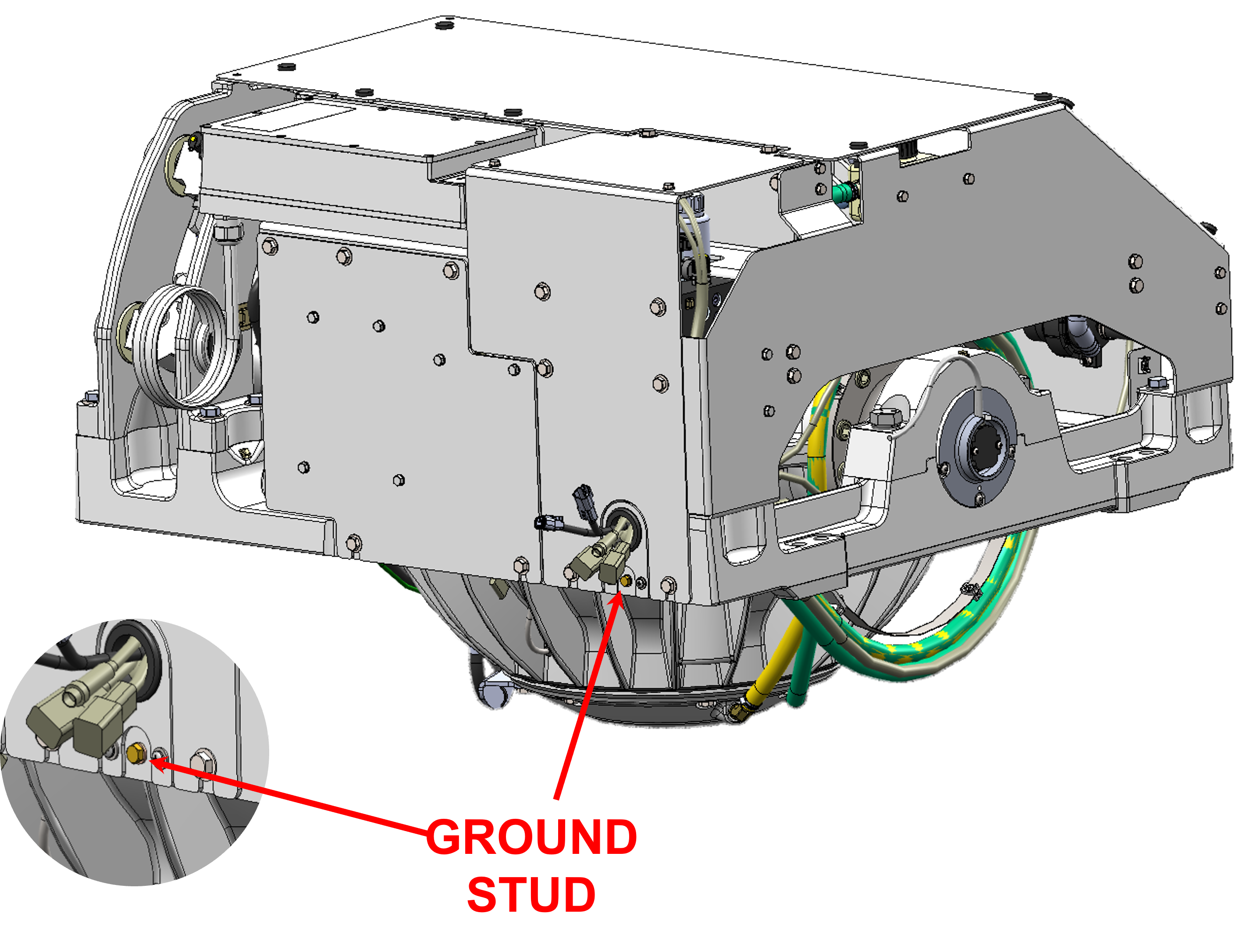
Note: THIS LOCATION SHOULD ONLY BE USED FOR GROUNDING THE SEAKEEPER TO THE VESSEL GROUND
3.4 Electrical Equipment Mounting
Precautions: Each item of electrical equipment has specific mounting instructions. These instructions
should be followed to ensure proper function of the Seakeeper.
Do NOT move Seakeeper mounted components from their
locations or incorrect Seakeeper operation will result.
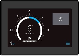
3.4.1 Seakeeper 9 Display Options
The Seakeeper 9 includes a 5″ Touch Screen Display (P/N 30296) standard. The 5″ Touch Display can be integrated with compatible Multifunction Display systems, per the MFD Compatibility Technical Bulletins.
The Seakeeper MFD App provides an interface for controlling the Seakeeper 9 and viewing the Settings, Service, Info, and Alarm pages from a compatible MFD.
The following figures provide schematics of display options. The subsequent sections outline the instructions and references for connecting the Seakeeper 9 to MFD display option peer Figure 9.
3.4.2 Installing the Seakeeper 5″ Touch Display
The desired location of the Operator Station must be determined for the vessel arrangement. For example, the operator display may be located on the bridge console or near the Seakeeper if integrated with a compatible MFD.
- Touch Display Mounting Instructions, Surface Mount
- Console space required: Approx. 5.24 W x 3.70 H in. (133 x 94 mm)
- Mounting Instructions, Surface Mount: See Drawing No. 90438 – 5″ Operator Display Envelope and Mounting Details, for details.
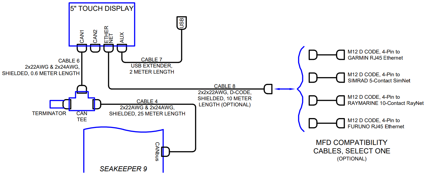
- CAN Communications Cable, Tee Adapter, and Terminator Mounting Instructions (See Figure 10)
- Rear mount Tee Adapter (P/N 30244) on vessel console panel, within 2 ft (0.6 m) of Display.
- Hardware required: One mounting screw for .197 in. (5 mm) diameter mounting hole on Tee Adapter. Terminator goes on the far end of the tee adapter from the Seakeeper.
- Run CAN Communications Cable (P/N 30332, Cable 4) from Seakeeper (female end) to Tee Adapter (male end).
- Install Can Cable (P/N 30301, Cable 6) from Tee Adapter (male end) to CAN1 connector at rear of 5″ Touch Display.
- Install Terminator (P/N 30249) into male connector of Tee Adapter.
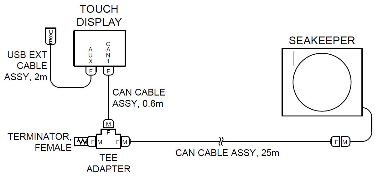
- USB Extension Cable Assembly Mounting Instructions
- Console space required: Approx. 2 W x 2 H in. (51 x 51 mm), within 6 ft (2 m) from Touch Display.
- Mounting Instructions, Surface Mount: Use panel cutout as shown in Section: Display Installation Template. Maximum panel thickness 1/8 in. (3.2 mm).
- Install sealed USB connector end of the extender cable assembly in panel from rear and secure with hex jam nut (provided) on front.
- Connect M12 connector end of the extender cable assembly to the rear of the Touch Display on receptacle AUX.
3.4.3 Connecting an Optional Compatible MFD
- The Seakeeper 9 can be connected to a variety of available MFD systems. Refer to the Technical Bulletins Section of the Seakeeper Technical Library for manufacturer specific MFD compatibility technical bulletins.
- MFD specific Technical Bulletins will be updated regularly as new MFD systems become compatible. Currently GARMIN, RAYMARINE, NAVICO (Simrad, Lowrance, B&G), and FURUNO offer compatible MFD models.
- Once a compatible MFD has been selected, refer to the appropriate manufacturer specific Technical Bulletin for integration instructions.
- Connect Seakeeper-supplied Cable 8 (P/N 30330), D-Code 10 m cable to MFD manufacturer-specific Ethernet adapter cable. Custom Ethernet cables for specific MFD manufacturers are available through Seakeeper and must be purchased with the Seakeeper 9 if connecting to an MFD.
3.4.4 Connecting a Second Operator Station
NOTE: A compatible MFD over the Seakeeper 5” Touch Screen Display is recommended as they economically provide broader features and functionality. Reference Seakeeper drawing 90467 – Helm Display 2nd Operator Station Kit and 90257 – Seakeeper 9 Cable Block Diagram for installation details.
Second Operator Station locations may be on a flybridge or in an engine room.
- Install 2nd 5″ Touch Display as first 5″ Touch Display in desired location.
- Install 2nd Operator Station Tee Adapter (P/N 30244) with Terminator (P/N 30249).
- Figure 11 shows the entire serial communications link for 2 Operator Stations. The Terminator must be installed on the Tee Adapter farthest from the Seakeeper.
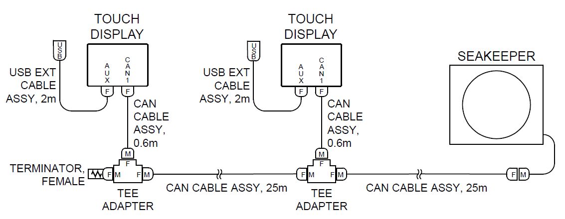
- Route a second CAN Cable Assembly (P/N 30332) from the 1st operator station (female end) to the 2nd Operator Station Tee Adapter as shown in Figure 11.
4.0 Cooling Installation
4.1 Cooling Installation Introduction
Reference Documents & Drawings:
90257 – Seakeeper 9 Cable Block Diagram
90251 – Seakeeper 9 Cooling Water Schematic
30331 – Seakeeper DC Seawater Pump Assembly
TB-90191 – Seawater Cooling Pump Recommendations
The Seakeeper 9 is shipped with the cooling circuit filled and ready for use. The Seakeeper 9 requires connection to a raw water pump, referred to as the seawater pump, to cool the closed loop cooling circuit on the unit. The required seawater flow through the Seakeeper 9 heat exchanger is between 4 – 8 GPM (15.1 – 30.3 LPM), under all vessel operating conditions. Prior to operation, confirmation of glycol level is required.
Seakeeper offers a compatible self-priming DC Seawater Pump (P/N 30331) that is pre-wired for the Seakeeper 9 installation and covered under the standard Seakeeper Warranty. See Drawing No. 30331, Seaflo Seawater Pump Assembly for details and the Seakeeper Options and Accessories Price List for pricing information.
4.2 Cooling System Considerations
- Installer is responsible for supplying a dedicated seawater pump and associated plumbing. Seawater connections on the Seakeeper heat exchanger mate with ¾ in. (19 mm) hose. An optional seawater pump can be purchased through Seakeeper, P/N30331.
- The seawater pump is powered by Cable 5, via “SW Pump 24 VDC Out” on the Seakeeper 9, as outlined in Electrical Installation Section.
- This pump must operate on 24 VDC, 10 A OR 12 VDC, 15 A power. Pumps requiring other voltages or higher current can still be controlled by using this supply to trigger an installer-supplied relay but a separate source of power must be provided.
- A dedicated through-hull fitting should be installed for each Seakeeper unit onboard the vessel to ensure sufficient seawater flow to each unit.
- It is recommended that the seawater pump is located below the waterline, as close to the baseline of the vessel as practically possible, to maintain positive inlet pressure on the pump in all operating conditions.
- A self-priming seawater pump is recommended to maintain water flow in all underway conditions. Cavitation can occur at the seawater inlet and potentially cause an air-lock condition restricting seawater flow to the heat exchanger.
- Vented loops are optional and should only be considered with centrifugal style pumps. Self-priming or positive displacement style pumps do not require a vented loop, this includes Seakeeper P/N 30331.
- Maximum seawater pressure in heat exchanger is 20 psi (1.4 bar)
- Seawater flow requirement through heat exchanger is 4 GPM (15.1 LPM) minimum and 8 GPM (30.3 LPM) maximum under all operating conditions of the boat. When sizing seawater pump, installer should factor in losses for raw water plumbing. In addition to initial operation at dock, new Seakeeper installations should be checked to be within the flow requirements while vessel is at speed. Flows higher than 8 GPM (30.3 LPM) could affect heat exchanger life.
4.3 Connecting Seawater to Heat Exchanger
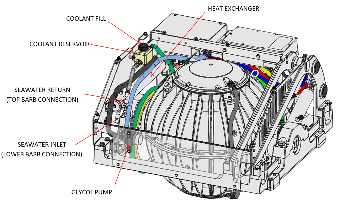
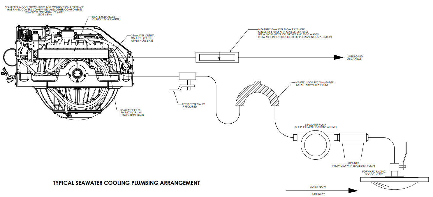
Refer to Figure 4 for typical Seakeeper 9 seawater plumbing arrangement.
- Connect seawater from installer-supplied pump to lower ¾ in. (19 mm) hose barb on heat exchanger. (See Figure 1) Use the same practices as other below waterline seawater plumbing. Required flow rate is 4 GPM (16 LPM) minimum and 8 GPM (30.3 LPM) maximum.
- Connect seawater discharge (upper hose barb) to overboard drain. (See Figure 1) Use the same practices as other below waterline seawater plumbing.
- In addition to initial operation at dock, new installations should be checked for minimum 4 GPM (16 LPM) flow while vessel is at speed and when backing down. If no other method of confirming flow is available, discharge line may be temporarily diverted to a bucket. Flow is calculated from time to fill a known volume. A self-priming seawater pump (customer/installer supplied) may be required due to installation location to maintain water flow in all underway conditions where cavitation near the intake may occur and potentially cause an air-lock condition restricting seawater flow to the heat exchanger.
- Inspect raw water plumbing after sea trial for any signs of leakage.
- Heat exchanger contains removable endcaps to provide access for cleaning the tube bundle.
4.4 Seakeeper Optional DC Seawater Pump (P/N 30331)
- Seakeeper offers a self-priming DC Seawater pump operated at 24 VDC for the Seakeeper 9.
- The pump assembly is pre-wired for connection to Seakeeper 9 Cable 5, “SW Pump Output” and includes a seawater strainer and various fittings. The pump specifications are as follows:
| Volts | 24 VDC |
| Rated Flow | 5.5 GPM (nominal) |
| Overcurrent Protection Rating | 15 A |
| Ignition Protection | ISO 8846 or equivalent |
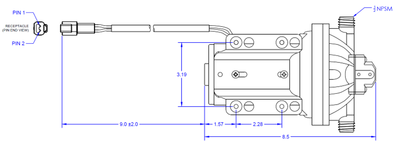
NOTE: Only use SeaFlo-provided threaded fittings with DC Seawater Pump 30331.
4.5 Adding Coolant
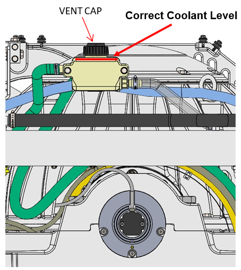
- Cooling system is filled to proper level when shipped, with a mixture of 50% ethylene glycol and 50% distilled water. The reservoir and clear tube between heat exchanger and reservoir should be filled with green coolant mixture, as shown in Figure 5. If level has dropped, check for evidence of leaks at all connections before adding fluid as described below. If coolant is at the correct level, skip to Section: Connecting Seawater to Heat Exchanger.
- Note: Some amount of entrained air in the fluid is normal and acceptable. This air will be evident by some cloudiness of the fluid. As long as the fluid remains at the specified fill level during operation, the remaining cloudiness is not an issue.
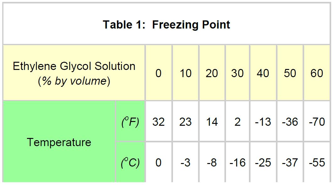
- Mix 50% ethylene glycol with 50% distilled water in a clean container. Refer to Table 1 or glycol manufacturer’s literature for freezing points.
- Remove vent cap on top of reservoir. Pour mixture in until level reaches 2/3 reservoir as shown in Figure 5. Filling reservoir above this level will not cause any damage but coolant may be expelled from vent on top of cap due to normal thermal expansion of coolant.
- Connect 24 V to controller.
- At the Display check for any ALARMS
- Press the POWER ON/OFF button.

- The flywheel will start to spin and the glycol pump will start.
- Recheck glycol level with fluid circulating in coolant circuit. Sight down inside reservoir and check that coolant level is above upper port on reservoir as shown in Figure 4. Replace cap.
- After several minutes of running, press POWER ON/OFF button
 to turn power off to the flywheel.
- At the Display check for any ALARMS
- The cooling system is self-purging. If small amounts of air are in the system, they will most likely be dislodged during the first sea trial. Re-check glycol level after sea trial and add fluid if required.
5.0 Installation Checklist and Required Supplies
5.1 Installation Checklist
Please Complete Checklist and E-mail to
customerservice@seakeeper.com or telefax to +1.410.326.1199
5.1.1 Mechanical Checklist
(Reference Installation Manual Section: Mechanical Installation)
_____ Seakeeper foundation installed in hull
_____ Foundation bolts torqued to specification
5.1.2 Electrical Checklist
(Reference Seakeeper Drawing No. 90257 – Seakeeper 9 Cable Block Diagram & Installation Manual Section: Electrical Installation)
Mount Components
_____ Display (near helm)
Connect Customer Supplied Cables
Cable 6 (Customer supplied)
_____ Install lugs on both ends of customer-supplied 10 AWG ground cable
_____ Connect one end of Cable 6 to nearest vessel ground and other end to Seakeeper 9 rear brace
Connect Seakeeper Supplied Cables
Cable 1
_____ Connect Cable 1 from Seakeeper to 24 VDC power at customer-supplied connection box or directly
to circuit breaker
_____ Plug connector of Cable 1 into mating connector on Seakeeper wire harness
Cable 2
_____ Connect Cable 2 from Drive Box to 230 VAC single phase at customer-supplied connection box
or directly to circuit breaker
Cable 8
_____ Connect Cable 8 from Seakeeper to 24 VDC /10 A power at customer-supplied connection box
or directly to circuit breaker
_____ Plug connector of Cable 8 into mating connector on Seakeeper wire harness at DC SW Pump In
Cable 5
_____ Connect Cable 5 from DC SW Pump Out to 24 VDC seawater pump
Cable 3
_____ Connect female end of CAN communications Cable 3 to mating connector on Seakeeper wire
harness
_____ Route CAN communications Cable 3 from Seakeeper to helm (male end goes to helm)
_____ Connect male end of CAN communications Cable 3 at helm to CAN Tee Adapter
_____ Connect Display and Seakeeper-supplied Cable 4 to CAN Tee Adapter with CAN Terminator
5.1.3 Cooling Checklist
(Reference Installation Manual Section: Cooling Installation)
_____ Verify coolant level in heat exchanger coolant reservoir (2/3 maximum)
_____ Connect seawater hoses / open sea cocks to heat exchanger and test seawater pump
_____ Verify 4 GPM (15 LPM) minimum and 8 GPM (30 LPM) maximum seawater flow through heat
heat exchanger under all operating conditions of the boat
5.1.4 Start Up Checklist
(Reference Installation Manual Section: Start Up & Operation Manual Section: System Operation)
_____ Remove lifting eyebolts and install cover panels
_____ Turn on 24 VDC circuit breakers
_____ Turn on 230 VAC circuit breaker
_____ Verify display works and no ALARMS are present
_____ If display does not work, turn off both circuit breakers immediately
_____ Check polarity of 24 VDC power per Section 2.2.5
_____ Follow instructions in Installation Manual Section: Start Up Instructions to turn on the Seakeeper
_____ Verify seawater pump turns on while the Seakeeper is turned ON
_____ Verify no ALARMS are present
_____ Follow instructions in Installation Manual Section: Startup Instructions to turn off the Seakeeper
_____ AC & DC power and seawater pump may be turned off after the Seakeeper is turned off by placing the
Seakeeper in LOCK mode and turning the Seakeeper off
_____ Seakeeper 9 takes 4+ hours to coast down to 0 RPM from full speed
5.2 Required Supplies Needed for Seakeeper Installation
5.2.1 Required Supplies Needed for Seakeeper Installation
(Not Supplied with the Seakeeper)
| Item | Description | Qty | Installation Manual Reference Section | Other Reference | System |
|---|---|---|---|---|---|
| 1 | Adhesive and cleaning supplies for bonding to hull | AR | Mechanical Installation | Mechanical | |
| 2 | Soundproofing Considerations | Selection of Installation Location | Mechanical | ||
| 3 | Spreader bar for lifting Seakeeper | 1 | Transport and Unpacking | Mechanical | |
| 4 | Threaded insert: M14-2 x 1.5DIA (21 mm) | Mechanical Installation | Dwg 90255 | Mechanical | |
| 5 | Marine Sealant | AR | Mechanical Installation | Dwg 90255 | Mechanical |
| 6 | Nickel-Based Anti-Seize (SAF-T-EZE SBT-4N, or similar) | AR | Mechanical Installation | Dwg 90255 | Mechanical |
| 7 | Circuit Breaker, AC, 2-Pole, 20 A | 1 | Electrical Equipment Power Connections | Dwg 90257 | Electrical |
| 8 | Circuit Breaker, DC, 1-Pole, 10 A, Gyro Controller | 1 | Electrical Equipment Power Connections | Dwg 90257 | Electrical |
| 9 | Circuit Breaker, DC, 1-Pole, 15 A max, Seawater Pump | 1 | Electrical Equipment Power Connections | Dwg 90257 | Electrical |
| 10 | M6 terminal lug for grounding Seakeeper at rear brace | 1 | Electrical Equipment Ground Connections | Dwg 90257 | Electrical |
| 11 | Marine Cable, Green, 10 AWG, Cable 6 ground connection (used with item 11) | AR | Electrical Equipment Ground Connections | Dwg 90257 | Electrical |
| 12 | Seawater pump, 24 VDC | 1 | Electrical Equipment Power Connections | Dwg 90257 | Electrical |
| 13 | Relay for seawater pump control (Not required if using 24 VDC pump) | 1 | Electrical Equipment Power Connections | Electrical | |
| 14 | Through-hull fittings (1 pick-up, 1 overboard discharge) | 2 | Cooling Installation | Dwg 90251 | Cooling |
| 15 | Seacock Valve | 1 | Cooling Installation | Dwg 90251 | Cooling |
| 16 | Seawater Strainer (Included with Seakeeper Seawater Pump P/N 30331) | 1 | Cooling Installation | Dwg 90251 | Cooling |
| 17 | 3/4 in. ID Seawater Hose | AR | Connecting Seawater | Dwg 90251 | Cooling |
| 18 | Hose clamps for seawater plumbing to ¾ in. (19 mm) hose barb (2 per hose barb) | AR | Connecting Seawater | Dwg 90251 | Cooling |
AR = As Required
Dwg = Drawing
5.2.2 List of Common Tools That May Be Required for Installation
| Item | Description | Use |
|---|---|---|
| 1 | Wire cutter | DC Power, AC Power cables |
| 2 | Wire stripper | DC Power, AC Power cables |
| 3 | 13 mm Socket Wrench | Cover Panels |
| 4 | Phillips head screwdriver | Cover Panels |
| 5 | 3 mm hex key | Gimbal sensor mount plate |
| 6 | 2.5 mm hex key | Gimbal angle sensor |
| 7 | ¼ in. nutdriver | Hose clamps |
| 8 | Terminal or quick disconnect crimper | Power cables |
| 9 | Utility knife | Scoring cable jackets |
| 10 | 10 mm Socket Wrench | Ground Stud |
6.0 Start Up
6.1 Start Up Introduction
This section describes the first startup of the Seakeeper.
Reference Documents & Drawings:
Link to Seakeeper 9/7HD Reference Documents
- 90223 – Seakeeper 9 Operation Manual
- Previous sections for mechanical, electrical and cooling installation must be completed before this startup sequence is initiated.
- Before continuing, covers must be installed unless the Seakeeper is inaccessible and there is no risk to injury. Also, the area around the Seakeeper must be clear of personnel and equipment.
6.2 Start Up Instructions
- Energize 24 VDC supplies (Control and DC Seawater Pump power) at the customer-supplied electrical disconnect.
- Supply 208-230 VAC to Motor Drive Box at customer-supplied electrical disconnect.
- If seawater pump for the Seakeeper is not supplied through Cable 5 from Seakeeper 9 wire harness, turn on the boat’s AC or DC dedicated circuit breaker that supplies power to the seawater pump.
- With system powered up check the display for any ALARMS. If there are any ALARMS present they must be corrected first.
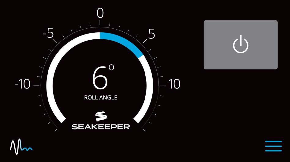
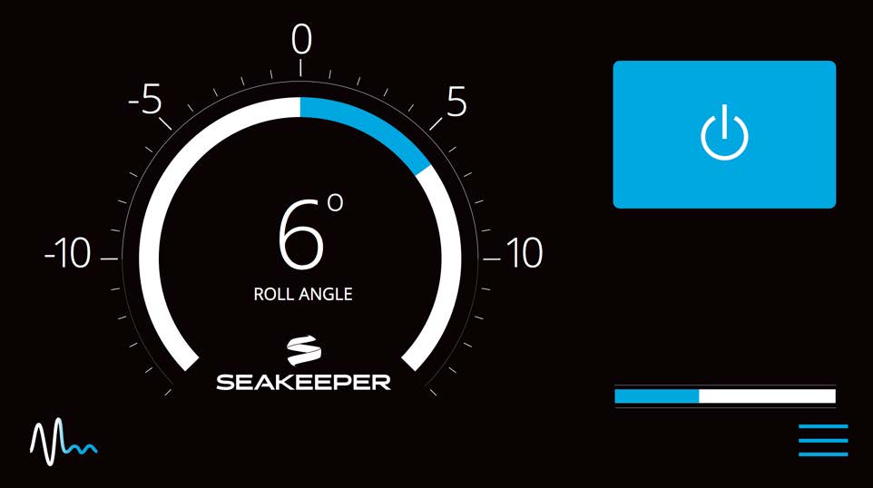
- Press the Seakeeper ON/OFF Button on Display. The progress bar will appear and indicate how soon the Seakeeper will be available for stabilization. When the Seakeeper is initialized and up to minimum operating speed, the stabilize button
 will appear. At this point, the Seakeeper is available for stabilization.
- The seawater pump should have started when the ON/OFF button on the display was depressed. Confirm pump operation and flow rate, if practical. Required flow is 4 GPM (15 LPM) minimum and 8 GPM (30 LPM) maximum.
- Verify that there are no ALARMS present. If an ALARM is present, it will be displayed.
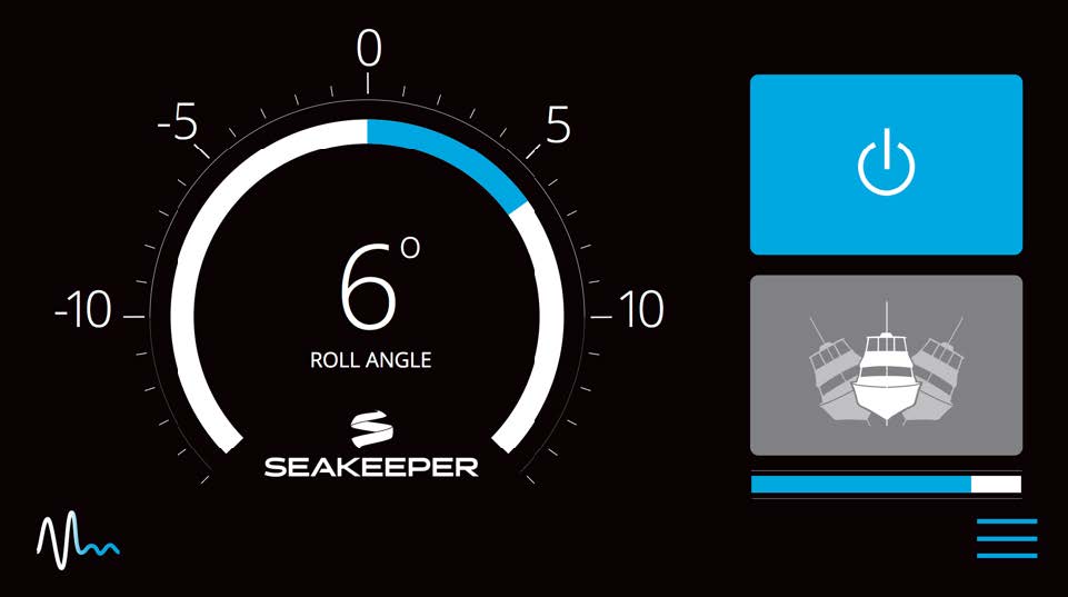
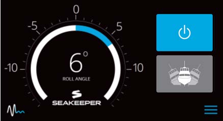
- When the Seakeeper reaches its maximum operating speed where maximum stabilization is available, the progress bar will disappear and the Seakeeper is available for maximum stabilization. Press the stabilize button. The button will turn blue indicating that the Seakeeper is stabilizing the roll motion.
- Verify that there are no ALARMS. If an ALARM is present, it will be displayed.
- Press the STABILIZE Button
 to turn stabilization off. Then press the Seakeeper ON/OFF Button to power the Seakeeper down.
 - During normal operation, the Seakeeper should be stopped when stabilization is no longer required. This maximizes long term life as it allows the Seakeeper to start the coast down cycle before cooling is shutoff. Once the vessel is secured in the slip and the crew has shut down the generator and engines, the AC and DC breakers that control the Seakeeper should be switched to the OFF position. The Seakeeper will continue to spool down to 0 RPM. No cooling is required during this time. Note the Seakeeper 9 will take 4+ hours to coast down to 0 RPM from full speed. When the flywheel has stopped the service screen will indicate 0 RPM.

7.0 Revision History
| REVISION | DESCRIPTION | DATE |
| 1 | Initial release | 21APR2014 |
| 2 | Added isolation gaskets, removed PN 90264 (insert plate), added detail on drilling/tapping | 09OCT2014 |
| 3 | Minor edits | 09FEB2015 |
| 4 | Adhesive tip clamp removed, removed Plexus instructions, removed flush mount display instructions, display template change | 06MAR2015 |
| 5 | Saddle surface bonding area changed, reinserted plexus details, minor edits throughout | 01JUN2015 |
| 6 | Added 7HD, removed word gyro from body, Fixture plate changed (hole dia.), Plexus alternative offered, minor edits throughout | 26JAN2017 |
| 7 | Removed Plexus details, 5″ Touch screen intro | 20OCT2017 |
| 8 | Minor edits, replaced images with Pan World glycol pump | 02JUL2021 |
| 9 | Updated address, added installation dwg references, clearance changes, thru-bolt added | 24SEP2021 |
| 10 | Added updated cooling system. Deleted 7HD model. Added FRB changes. Minor edits throughout document. | 08MAR2023 |