Seakeeper 9 Installation Manual (90222-10); S/N 9-212-3388 to 9-234-4899
3.4 Electrical Equipment Mounting
Precautions: Each item of electrical equipment has specific mounting instructions. These instructions
should be followed to ensure proper function of the Seakeeper.

Do NOT move Seakeeper mounted components from their
locations or incorrect Seakeeper operation will result.
3.4.1 Seakeeper 9 Display Options
The Seakeeper 9 includes a 5″ Touch Screen Display (P/N 30296) standard. The 5″ Touch Display can be integrated with compatible Multifunction Display systems, per the MFD Compatibility Technical Bulletins.
The Seakeeper MFD App provides an interface for controlling the Seakeeper 9 and viewing the Settings, Service, Info, and Alarm pages from a compatible MFD.
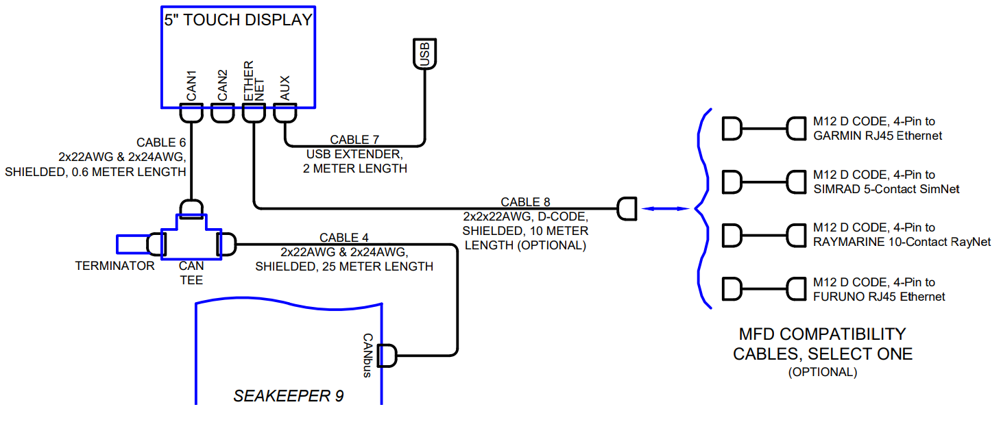
The following figures provide schematics of display options. The subsequent sections outline the instructions and references for connecting the Seakeeper 9 to MFD display option peer Figure 9.
3.4.2 Installing the Seakeeper 5″ Touch Display
The desired location of the Operator Station must be determined for the vessel arrangement. For example, the operator display may be located on the bridge console or near the Seakeeper if integrated with a compatible MFD.
- Touch Display Mounting Instructions, Surface Mount
- Console space required: Approx. 5.24 W x 3.70 H in. (133 x 94 mm)
- Mounting Instructions, Surface Mount: See Drawing No. 90438 – 5″ Operator Display Envelope and Mounting Details, for details.
- CAN Communications Cable, Tee Adapter, and Terminator Mounting Instructions (See Figure 10)
- Rear mount Tee Adapter (P/N 30244) on vessel console panel, within 2 ft (0.6 m) of Display.
- Hardware required: One mounting screw for .197 in. (5 mm) diameter mounting hole on Tee Adapter. Terminator goes on the far end of the tee adapter from the Seakeeper.
- Run CAN Communications Cable (P/N 30332, Cable 4) from Seakeeper (female end) to Tee Adapter (male end).
- Install Can Cable (P/N 30301, Cable 6) from Tee Adapter (male end) to CAN1 connector at rear of 5″ Touch Display.
- Install Terminator (P/N 30249) into male connector of Tee Adapter.
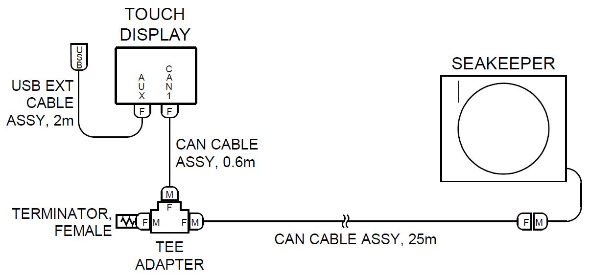
- USB Extension Cable Assembly Mounting Instructions
- Console space required: Approx. 2 W x 2 H in. (51 x 51 mm), within 6 ft (2 m) from Touch Display.
- Mounting Instructions, Surface Mount: Use panel cutout as shown in Section: Display Installation Template. Maximum panel thickness 1/8 in. (3.2 mm).
- Install sealed USB connector end of the extender cable assembly in panel from rear and secure with hex jam nut (provided) on front.
- Connect M12 connector end of the extender cable assembly to the rear of the Touch Display on receptacle AUX.
3.4.3 Connecting an Optional Compatible MFD
- The Seakeeper 9 can be connected to a variety of available MFD systems. Refer to the Technical Bulletins Section of the Seakeeper Technical Library for manufacturer specific MFD compatibility technical bulletins.
- MFD specific Technical Bulletins will be updated regularly as new MFD systems become compatible. Currently GARMIN, RAYMARINE, NAVICO (Simrad, Lowrance, B&G), and FURUNO offer compatible MFD models.
- Once a compatible MFD has been selected, refer to the appropriate manufacturer specific Technical Bulletin for integration instructions.
- Connect Seakeeper-supplied Cable 8 (P/N 30330), D-Code 10 m cable to MFD manufacturer-specific Ethernet adapter cable. Custom Ethernet cables for specific MFD manufacturers are available through Seakeeper and must be purchased with the Seakeeper 9 if connecting to an MFD.
3.4.4 Connecting a Second Operator Station
NOTE: A compatible MFD over the Seakeeper 5” Touch Screen Display is recommended as they economically provide broader features and functionality. Reference Seakeeper drawing 90467 – Helm Display 2nd Operator Station Kit and 90257 – Seakeeper 9 Cable Block Diagram for installation details.
Second Operator Station locations may be on a flybridge or in an engine room.
- Install 2nd 5″ Touch Display as first 5″ Touch Display in desired location.
- Install 2nd Operator Station Tee Adapter (P/N 30244) with Terminator (P/N 30249).
- Figure 11 shows the entire serial communications link for 2 Operator Stations. The Terminator must be installed on the Tee Adapter farthest from the Seakeeper.
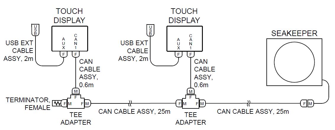
- Route a second CAN Cable Assembly (P/N 30332) from the 1st operator station (female end) to the 2nd Operator Station Tee Adapter as shown in Figure 11.