Seakeeper 9 Installation Manual (90222-10); S/N 9-212-3388 to 9-234-4899
4.3 Connecting Seawater to Heat Exchanger
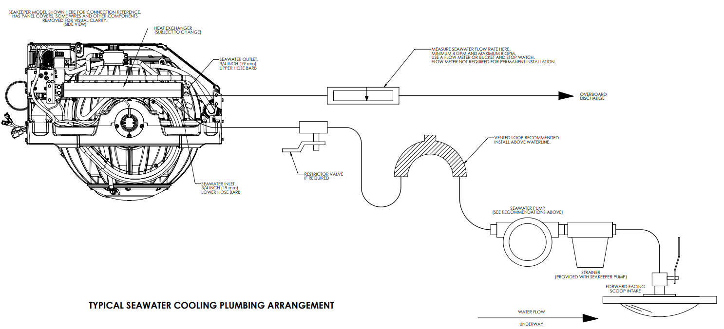
Refer to Figure 4 for typical Seakeeper 9 seawater plumbing arrangement.
- Connect seawater from installer-supplied pump to lower ¾ in. (19 mm) hose barb on heat exchanger. (See Figure 1) Use the same practices as other below waterline seawater plumbing. Required flow rate is 4 GPM (16 LPM) minimum and 8 GPM (30.3 LPM) maximum.
- Connect seawater discharge (upper hose barb) to overboard drain. (See Figure 1) Use the same practices as other below waterline seawater plumbing.
- In addition to initial operation at dock, new installations should be checked for minimum 4 GPM (16 LPM) flow while vessel is at speed and when backing down. If no other method of confirming flow is available, discharge line may be temporarily diverted to a bucket. Flow is calculated from time to fill a known volume. A self-priming seawater pump (customer/installer supplied) may be required due to installation location to maintain water flow in all underway conditions where cavitation near the intake may occur and potentially cause an air-lock condition restricting seawater flow to the heat exchanger.
- Inspect raw water plumbing after sea trial for any signs of leakage.
- Heat exchanger contains removable endcaps to provide access for cleaning the tube bundle.