Seakeeper 9 Installation Manual (90222-10); S/N 9-212-3388 to 9-234-4899
3.2 Electrical Equipment Power Connections
3.2.1 230 VAC Power Source Requirements
- 230 VAC (nominal), 1 Phase, 50/60 Hz, 20 A
- For installations of more than one Seakeeper, a separate circuit breaker should be used for each Seakeeper Motor Drive Box.
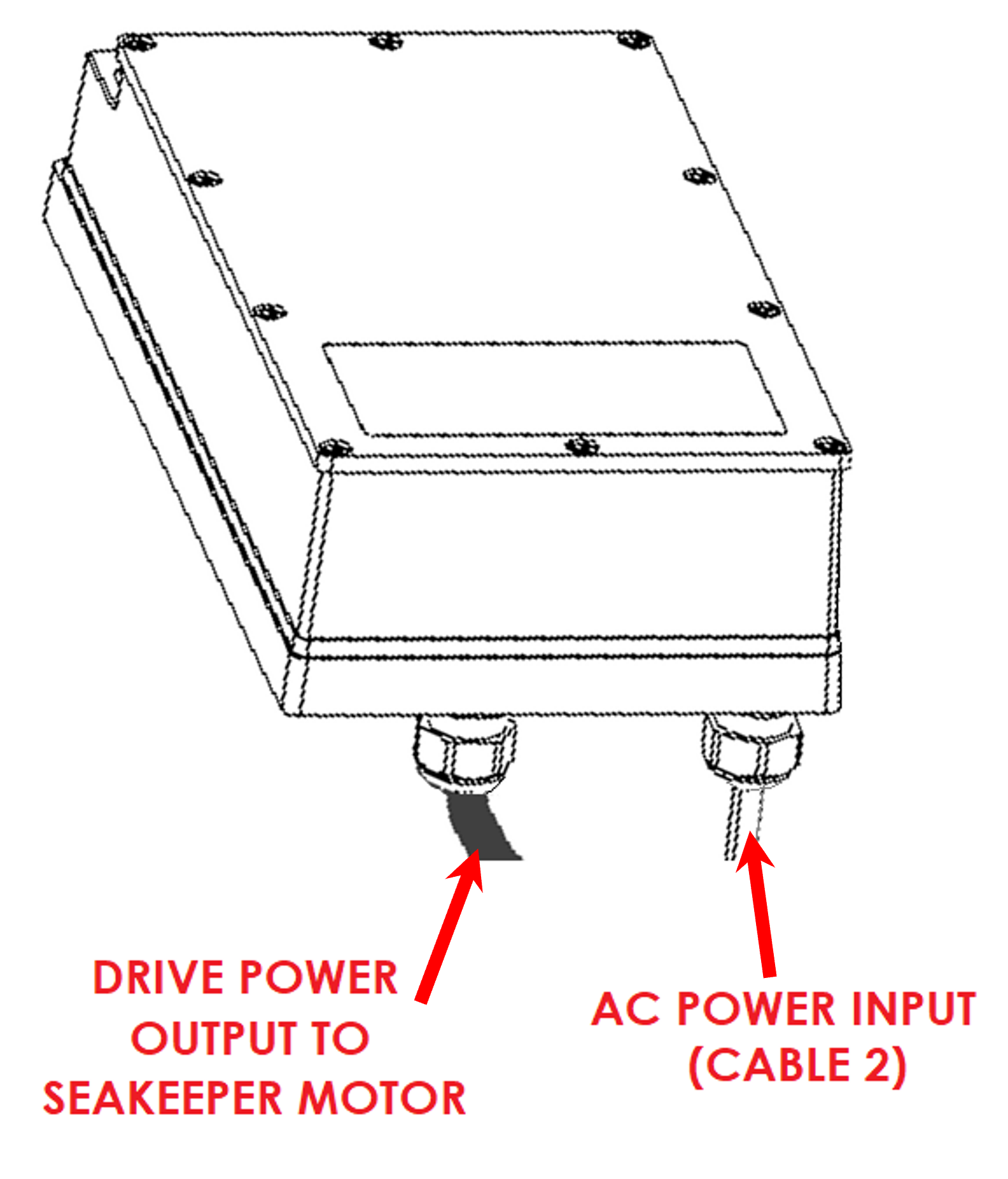
3.2.2 Drive Box AC Power Input Connection Instructions
- Cable 2: 3 x 10 AWG (3 x 6 mm2 CSA), 10 ft. (3 m) length, Seakeeper supplied pre-installed.
- Locate Cable 2 for AC power input to the Drive Box at the outward of three cable glands.
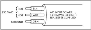
- Connect 230 VAC wires in Cable 2 to a 20 A, double-pole Circuit Breaker at an AC power distribution panel according to Figure 3 above.
3.2.3 24 VDC Power Source Requirements
- One 24 VDC, 10 A (Customer supplied) for Seakeeper Control Power, AND
- One 24 VDC, 10 A (Customer supplied) for DC Seawater Pump.
- A separate breaker should be used for each Seakeeper.
3.2.4 DC Power Connection Instructions
Reversing polarity on the DC power input to the Seakeeper can result in damaging the electronics in the control system.
- 24 VDC, 10 A, 2 x 12 AWG (3 x 4.0 mm2 CSA) customer supplied.
- Install Seakeeper provided DC Power Input Cable, P/N 20248 as Cable 1 (as shown in Drawing No. 90257).
- Route Cable 1 to DC Power Distribution Panel.
- Terminate positive (B+, Red ) conductor to +24 VDC.
- Terminate negative (B-, Black) conductor directly to battery negative terminal.
- Before connecting Cable 1 to Seakeeper, check for proper voltage and polarity with a DC multimeter using Figure 7 below.
- Connect Cable 1 to 24 VDC input receptacle on Seakeeper.
- Install Seakeeper provided DC Power Input Cable, P/N 20248 as Cable 1 (as shown in Drawing No. 90257).
3.2.5 DC Seawater Pump 24 VDC Power Input Connection Instructions

Connecting the DC Seawater pump in any other manner than recommended by Seakeeper may cause internal failure.
- Install Cable 8 (P/N 30327) to Seakeeper 9 “SW Pump DC In” (as shown in Drawing No. 90257) with overcurrent protection corresponding to seawater pump selected.
- Connect the 16AWG positive conductor (Red) through dedicated overcurrent protection device (customer supplied), maximum of 10 A, to dedicated battery isolation switch.
- Connect the 16 AWG negative conductor (Black) directly to battery negative terminal or DC main negative bus bar.
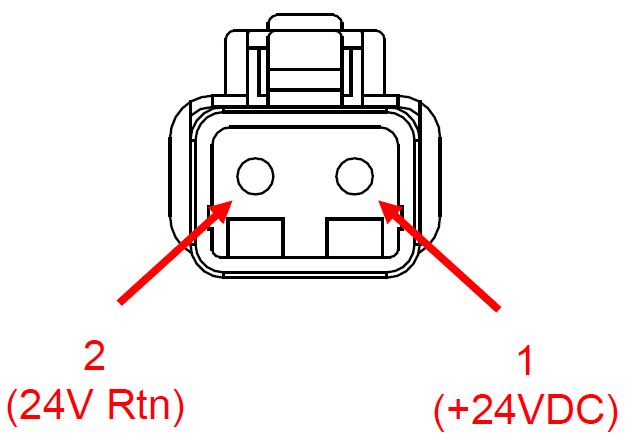
- Before connecting Cable 8 to Seakeeper, check for proper voltage and polarity with a DC multimeter using Figure 8 below.
- Connect Cable 8 to Seawater Pump 24 VDC In connector on the Seakeeper, DEUTSCH DT04-2P connector.
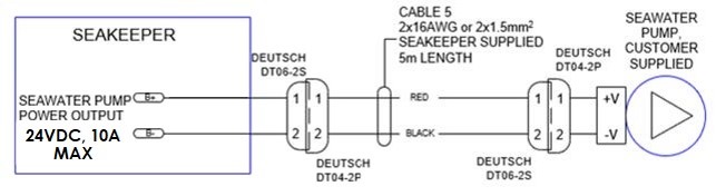
3.2.6 DC Seawater Pump 24 VDC Power Output Connection Instructions
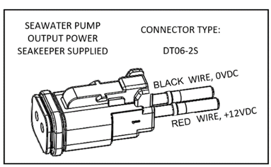
- Connect Cable 5 to the Seakeeper 9 “SW Pump 24VDC Out” for DC power to the seawater pump.
- Cable 5 is a 2 x 16 AWG cable, 16 ft (5m) length with a size 16 female Deutsch plug.
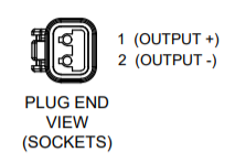
- Pumps rated at 24 VDC, 10 A maximum, customer-supplied, must be configured with a Deutsch DT series, 2-pin receptacle to mate with the connector shown in Figure 9.
- Cable 5 must be routed and installed in the vessel from the Seakeeper 9 “SW Pump 24VDC Out” Deutsch connector (pins end) to the DC seawater pump cable Deutsch connector (socket end).
- Connect Cable 5 plug end (socket end) to the customer-supplied receptacle end (pins end). The recommended wiring is shown in Figure 10.
- Contact Seakeeper if desired to install customer-supplied relay on Cable 5 to power seawater pump.