Mechanical Installation Manual (750, 750 Quad)
Seakeeper Ride | Mechanical Installation Manual (750, 750 Quad)
1. Introduction
Updated 12/20/24
This document is intended to give details and guidance to a boat builder or equipment installer on the proper procedure for the installation of the Seakeeper Ride system.
Because of the quantity of parts and careful installation requirements, set aside a clean, well- ventilated workspace, take inventory of necessary tools and parts, and review the entirety of this manual before setting to work. To gain a broad understanding of the installation process, read the Installation Overview.
The instructions in this manual should be repeated for all Controllers.
Two Options for Stability:
Seakeeper Ride 750 & Seakeeper Ride 750 Quad
Two products with different configurations were designed to provide stability for vessels with varying transom features. While the two systems are designed for the same sized vessels, the controller sizes and the transoms they serve differ. The Seakeeper Ride 750 system consists of two larger controllers and will fit most vessels in this size range, whereas the Seakeeper Ride 750 Quad system has four smaller controllers and is suitable for unique transoms that may have hull design elements that restrict available space.
Specific instances of these unique hull characteristics are detailed in the following manual, and will help you determine which system to install.
Note: Scan the QR code below to access Seakeeper Ride BILT 3D instructions.


WARNING: You must read and follow all instructions before installing and using the Seakeeper Ride system.

Note: All torque values are in-lbs NOT ft-lbs!
2. Safety Notices
2.1 Stability

This system is not intended, nor should it be expected, to provide underway dynamic stability beyond the limits of the hull itself. It is up to the captain of the vessel to ensure that the hull is maintained and operated in a safe manner, within the limits defined by the boat manufacturer.
2.2 Forces Applied to Hull
While underway, the Controllers transfer high forces at each of the mounting locations to the hull. Careful consideration should be given to the transom strength and condition to ensure it can hold the loads created by the Controllers.
For aluminum hulls, verify first the aluminum boat transom structure can withstand fast, repeated, and high forces created by the Seakeeper Ride Controllers during use before applying to the mounting surface.
Note: If an aluminum sheathing protects the transom structure of the vessel, then the load must be transferred from the sheathing to the transom structure on these installs.
2.3 Installation Personnel
It is imperative that the installer is familiar with bonding using high-strength adhesives to marine structures and has thoroughly inspected the transom where the Controllers are mounted to ensure it can withstand the loads the Controllers create while deployed at speed. If the installer has any doubt about the ability of the transom to support the loads, they should contact a licensed naval architect or marine engineer to do a structural analysis.
The installer must review the full installation manual and associated drawings prior to installation to ensure the installation procedure is fully understood.
FAILURE TO FOLLOW THESE INSTRUCTIONS MAY LEAD TO IMPROPER INSTALLATION AND FAILURE OF THE SEAKEEPER RIDE SYSTEM TO OPERATE AS INTENDED.
IMPORTANT! Installation of the Seakeeper Ride system requires knowledge and experience in marine alterations, including drilling and grinding fiberglass or other boat hull materials, applying high- strength adhesives, ability to inspect installation locations for fitment and potential obstructions, and marine electronics wiring. If the installer does not have knowledge and experience in these areas, the installer should contact a marine technician, engineer or naval architect for installation assistance.
2.4 Installation Tools
Use a properly calibrated torque wrench for final tightening of all bolts per this manual. Improper torque application to fasteners may cause damage to the system. Do not use power tools to install the bolts. This can cause galling and does not allow for the correct torque.
Note: All torque values are in-lbs NOT ft-lbs!
Unless otherwise specified, apply medium strength thread locking sealant to all fasteners prior to installation. Vibra-Tite VC-3 threadlocker is preferred and will be included in the packaging for this purpose. Because of the dissimilar metals of fasteners and hardware of Seakeeper Ride components specialty coatings are applied to the equipment to prevent corrosion in a marine environment. Avoid removal of these coatings to reduce corrosion.
3. Tools Needed
- Drill
- Dual Action Sander
- Oscillating Tool or Hacksaw
- Torque Wrench (25-130 in-lbs required)
- Socket Set (10mm, 13 mm required)
- Phillips Head Screwdriver
- Hex Bit Sockets (2.5, 4, 5 & 6 mm required)
- Hex Wrenches (Allen Keys) (2.5, 5 & 6 mm required)
- Torx Bit Socket (T30 required)
- Adjustable Wrench
- Squeegee, Putty Knife, or Tongue Depressor
- Digital Protractor
- 6-12 in. Straight Edge
- 3 ft Straight Edge
- Drill Bits or Hole Saw in Sizes 3/32 in. (2.4 mm), 9/64 in. (3.6 mm), 1/4 in. (6.4 mm) & 3/4 in. (19 mm)
- Approved two-part adhesive (See list below)
- Two-part Adhesive Cartridge Gun (Check mixing ratio compatibility)
- Two-part Adhesive Mixing Nozzles (Check mixing ratio compatibility)
- Marine Adhesive Sealant (3M 5200 is recommended)
- Masking Tape
- 60 Grit Sandpaper
- *Medium Strength Threadlocker (Vibra-Tite VC-3 is recommended)
- Threadlocker Activator/Primer (If Vibra-Tite VC-3 is not used)
- Denatured Alcohol
- Clean Gloves (recommended)
- Respirator
- Plain White Paper Towels
- Marker, Pen, or Pencil
*Vibra-Tite VC-3 will be included in the package. If an alternate threadlocker is used, a threadlocker activator/primer will likely be required for the threadlocker to cure properly with the stainless steel hardware.
Two-Part Adhesives
Approved adhesives and working times:
- Methyl Methacrylate Adhesives (MMAs)
- Plexus MA590 (90 minute)
- SciGrip SG300-40 (40 minute)
- Partite 7425 (25 minute)
- Crestabond M1- 60HV/2 (60 minute)
- Adhesivetech AT330 (18-32 minute)
- Acralock SA10-40 (40-50 minute)
- Epoxies (For epoxies, Section 8.6 – Removing Gel Coat must be followed)
- West Systems Six10 (42 minute)
- Pettit Flexpoxy (25 minute)
- Araldite 2015-1 (45 minute)
Adhesives, dispense guns, and solvent wipes can be purchased from Seakeeper Partner Center or online and local retailers.
Quantity:
| Controller Size | Minimum Adhesive Quantity (per boat) | Minimum Adhesive Quantity (per Controller) |
| 750 mm Quad | 1500 ml | 375 ml |
| 750 mm Dual | 1500 ml | 750 ml |

Two-part adhesives comes in multiple mixing ratios – 1:1, 2:1, or 10:1. Use the correct dispense gun and mixing nozzles for the two-part adhesive type. Failure to do so will result in poor adhesion and will void the system’s warranty.
WARNING: Check the adhesive being used to verify it is compatible with the hull material (epoxy resin fiberglass, polyester resin fiberglass, gel coat, etc). Some require a primer when used with certain materials. Plexus primer must be used if performing an aluminum installation with Plexus MMA.
4. Inventory Parts
Please review all parts included before proceeding. The following figure and table describe all parts included in the assembly. Review parts and ensure all parts are present before starting the installation procedure.
Components shown are per Controller. Dual Actuator systems will have two (2) times the components listed, and Quad Actuator systems will have four (4) times the components listed.

- Blade
- Seal Plate
- Actuator
- Actuator Plate
- 3 Degree Wedge Plate
- 4 Degree Wedge Plate
- 5 Degree Wedge Plate
- Transom Plate
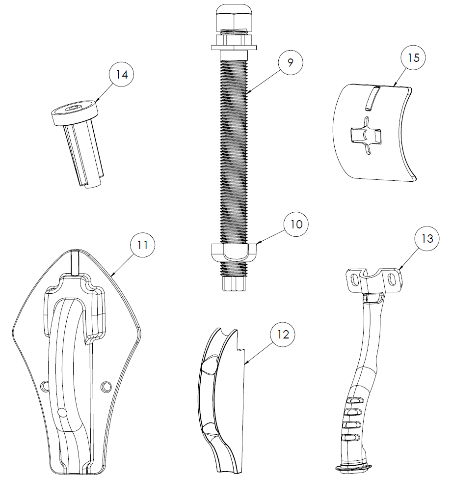
- Cable Gland Tube
- Cable Gland Nut
- Outer Cable Guide
- Inner Cable Guide
- Cable Support Guide
- Drill Guide Tube
- Drill Guide Follower
Hardware counts below are given in the format: x[QUAD ACTUATOR] / [DUAL ACTUATOR]
| Wedge Pack Hardware | Positioning Screws | |||
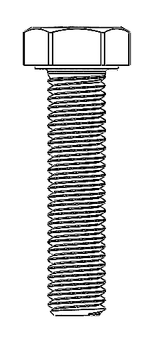 x3 / 5 M8-1.25 X 35 mm Hex Head Bolt | 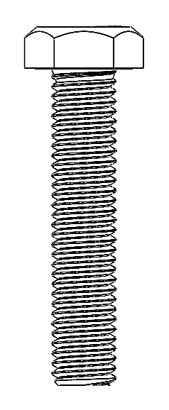 x3 / 5 M8-1.25 X 40 mm Hex Head Bolt |  x2 / 4 M8-1.25 X 55 mm Hex Head Bolt |  x2 / 4 M8-1.25 X 75 mm Hex Head Bolt |  x3 Phillips No. 8 x 1.25 in. Screw |
 x5 / 9 M8 Cylindrical Washer for Hex Head | x5 / 9 Transom Plate Bolt Cover |  x5 / 9 M8 Cylindrical Washer |  x5 / 9 M8 Wedgelock Washer |  x5 / 9 M8-1.25 Hex Nut |
| Seal Plate Hardware | Blade Hardware | |||
 x4 / 6 M6-1.0 x 30 mm Hex Head Bolt |  x4 / 6 M6 Washer |  x6 / 10 M6-1.0 x 16 mm Flathead Screw |  x4 M8-1.25 X 30 mm Hex Head Bolt |  x4 M8 Washer |
| Cable Routing Hardware | Endcaps | |||
 x2 Phillips No. 8 x 0.75 in. Screw |  x2 Phillips No. 8 x 1.5 in. Screw |  x2 Phillips No. 10 x 1.0 in. Screw | 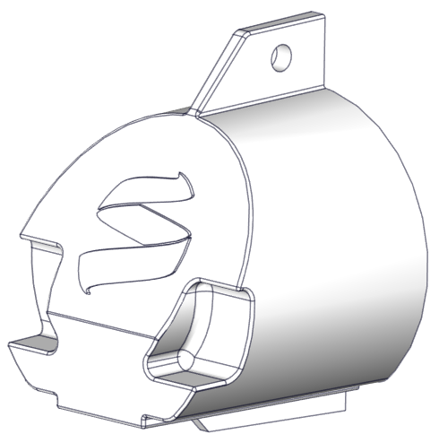 x0 / 2 Endcaps (Only included with Dual Actuator systems) |
Note: Vibra-tite 122 threadlocker will also be included in the packaging.
5. Identify Installation Location
Installation Location Introduction
The performance of the Seakeeper Ride system is a direct result of the proper mounting location of the Controllers. It is vital to abide by the criteria in the Seakeeper Ride Installation Location Guide to choose the optimal mounting point for the Controllers. Optional use of the Seakeeper Ride 750 Controller Tool will assist with locating where the Seakeeper Ride system will sit on the boat Hull and how much room it will take in order to install.
For new production installations, please consult with the Seakeeper Applications Engineering Team or a naval architect for the proper location of the Seakeeper Ride Controllers according to the hull shape, hull type, engine configuration, and other relevant application details.
Note: Seakeeper has adopted a notation of the following to describe multiple controller installations:
| P1 | Port 1 | Port Outside |
| P2 | Port 2 | Port Inside |
| S2 | Starboard 2 | Starboard Inside |
| S1 | Starboard 1 | Starboard Outside |
Details for the inside and outside controller beam wise locations will follow.
For refit installations, please review the following sections to determine the ideal location for the Seakeeper Ride Installation.
5.1 Longitudinal Location
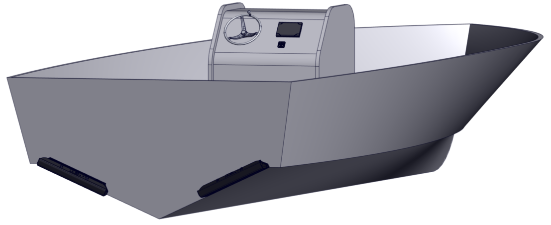
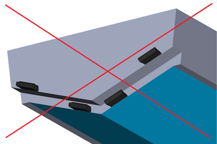
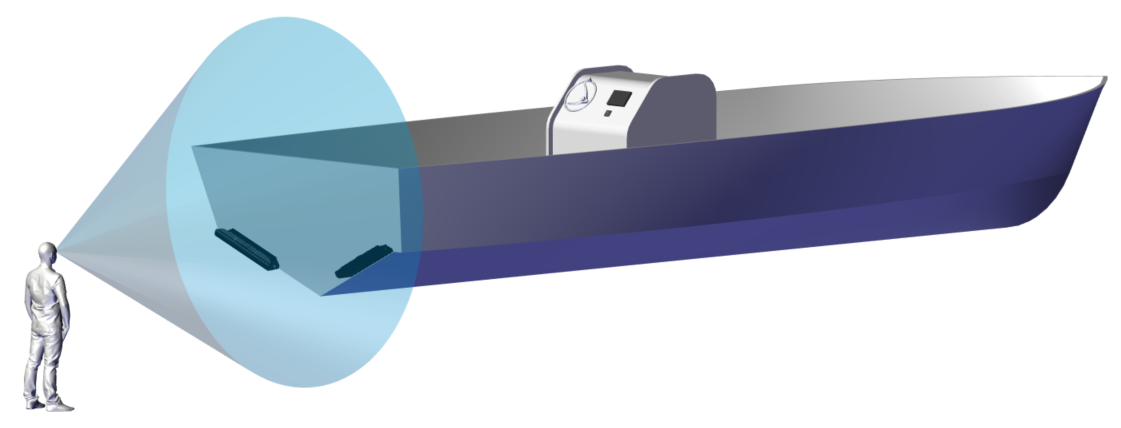
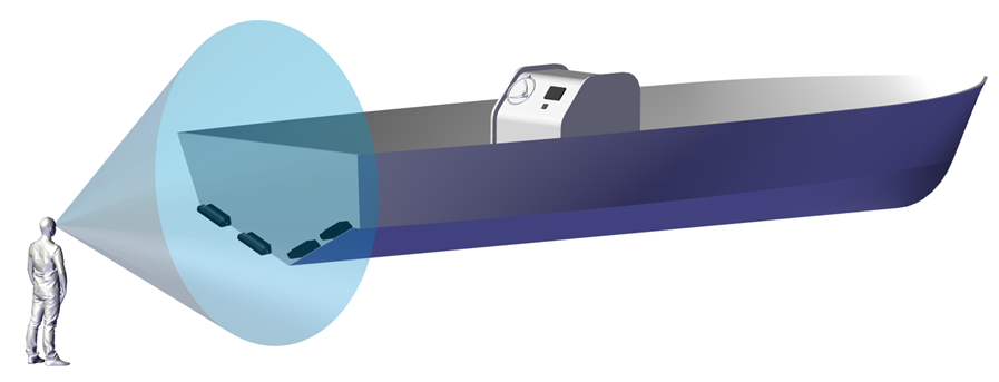
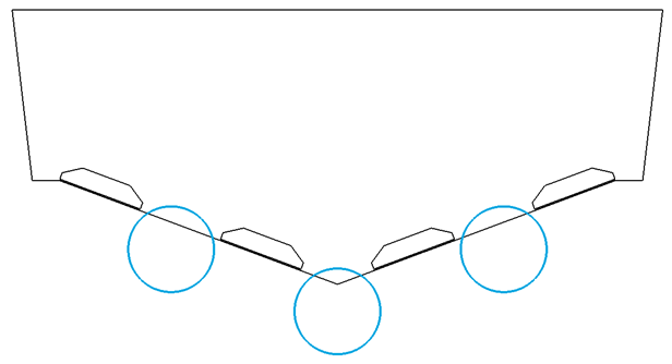
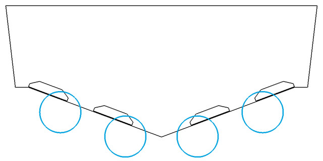
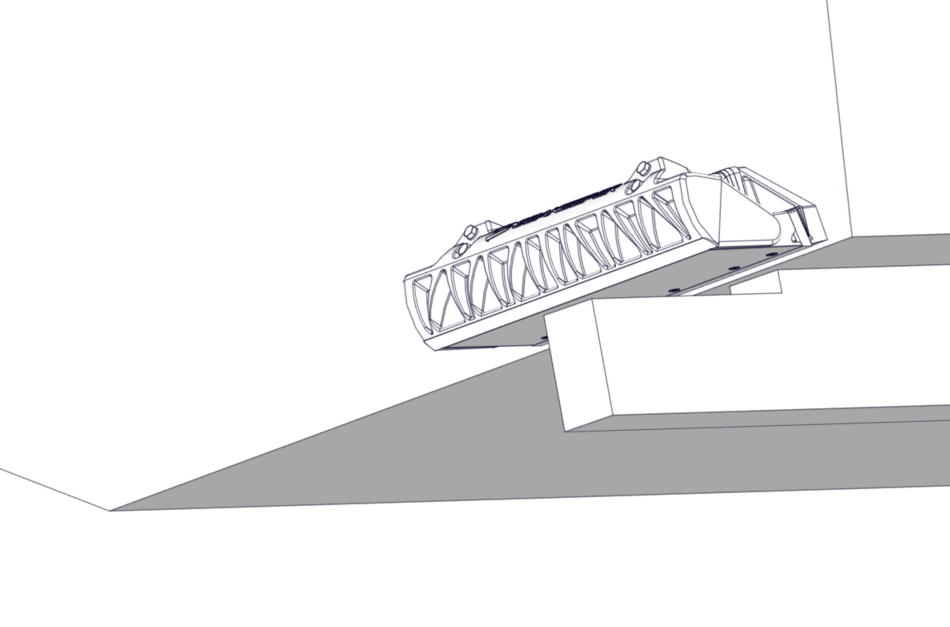
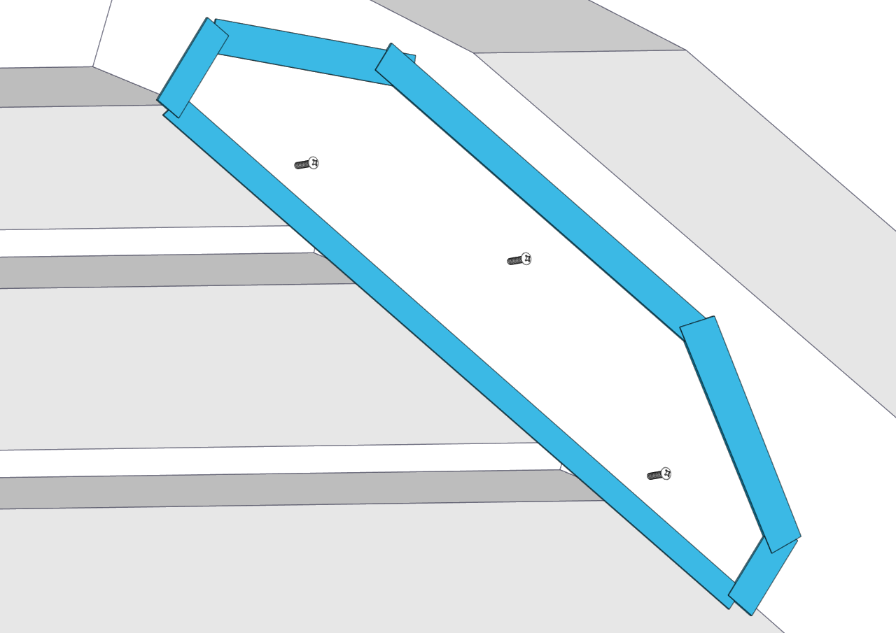
The Seakeeper Ride Controllers will be mounted to the transom, the approximately vertical surface at the aft end of the running surface, as shown in figures below.


In Quad Controller installations, the outer Controllers, P1 and S1, may be installed at a different longitudinal location from the inner Controllers, P2 and S2. All Controllers must be flush with the running surface of the hull, highlighted in blue in the examples below.
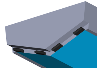
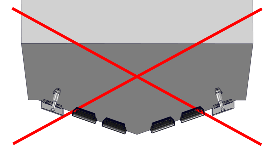
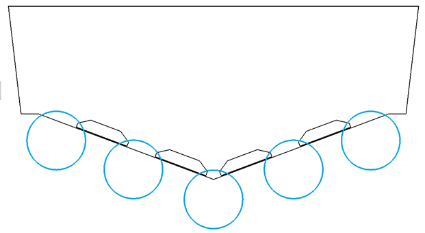
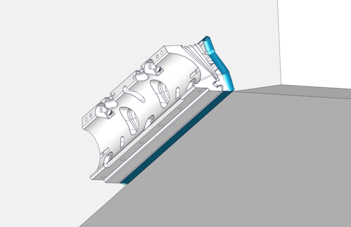
If any of the Controllers are installed above the running surface of the hull, they will not make contact with the water while at speed and be unable to influence boat motion as intended. See the example below of this type of incorrect installation.
5.2 Vertical Location
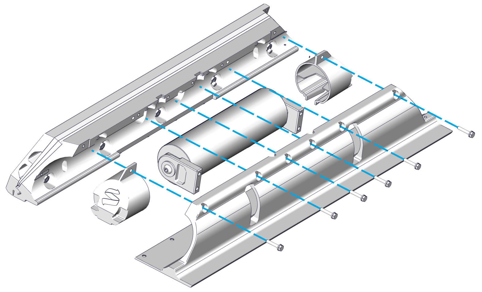
Seakeeper Ride’s Controllers must be mounted so that the bottom surface of the Seal Plate (Item Number 2 below) aligns flush and parallel with the hull bottom. The goal is to have the Seal Plate acting like an extension of the hull bottom. The Seal Plate’s location is determined by the Transom Plate (Item Number 8 below), which is affixed to the transom and adjusted up and down during installation to allow for fine-tuning the location.
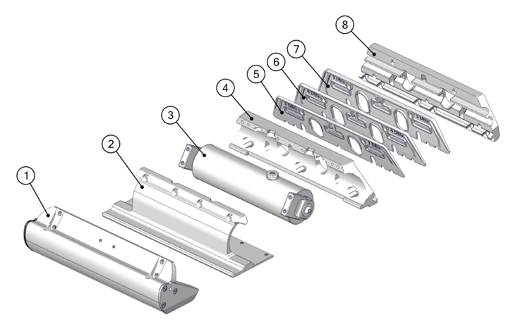
1) Blade
2) Seal Plate
3) Rotary Actuator
4) Actuator Plate
5) 5 Degree Wedge Plate
6) 4 Degree Wedge Plate
7) 3 Degree Wedge Plate
8) Transom Plate
Figure 8 – Seakeeper Ride 750 Controller Constituent Parts
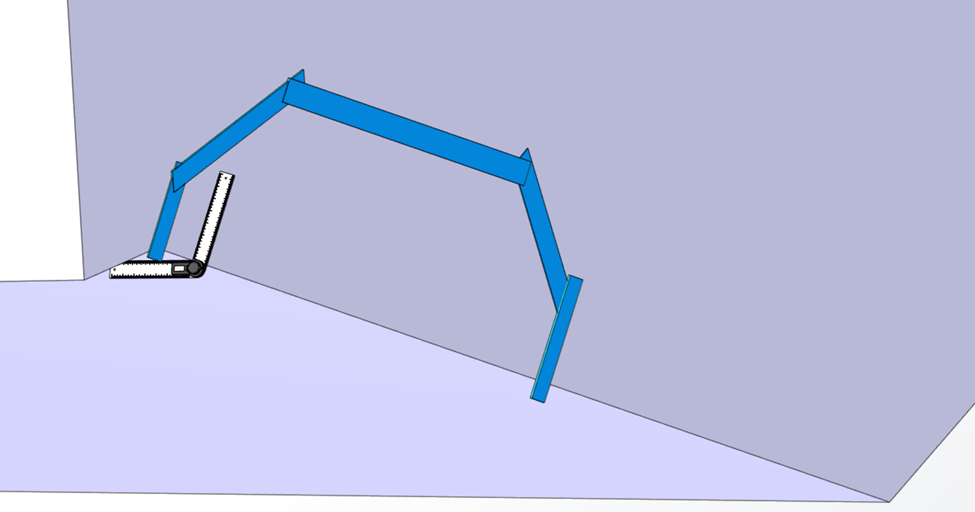
The Ride Reference Line (RRL) is a guide for where the bottom of the Controller should be when mounted. The RRL is a representation of the bottom edge of the transom where it meets the running surface of the hull. Because of the unique shapes of different hulls, the RRL may not follow the bottom edge of the hull exactly. The following examples give guidance on where the RRL should lie on hull bottoms that are not perfectly straight.
An example transom with an exaggerated radius is shown below. The RRL is shown in blue and is the intersection of the two straight edges.
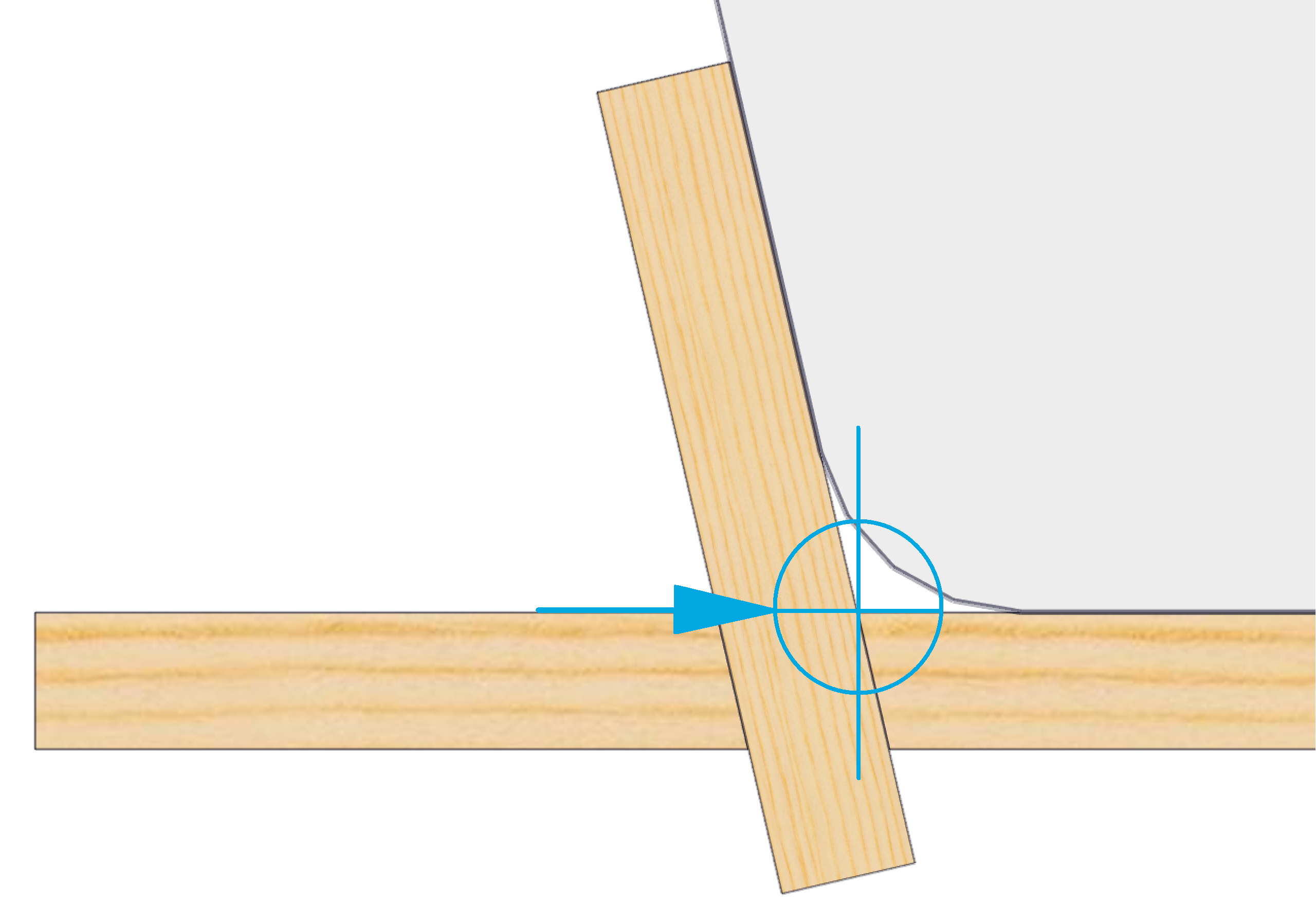
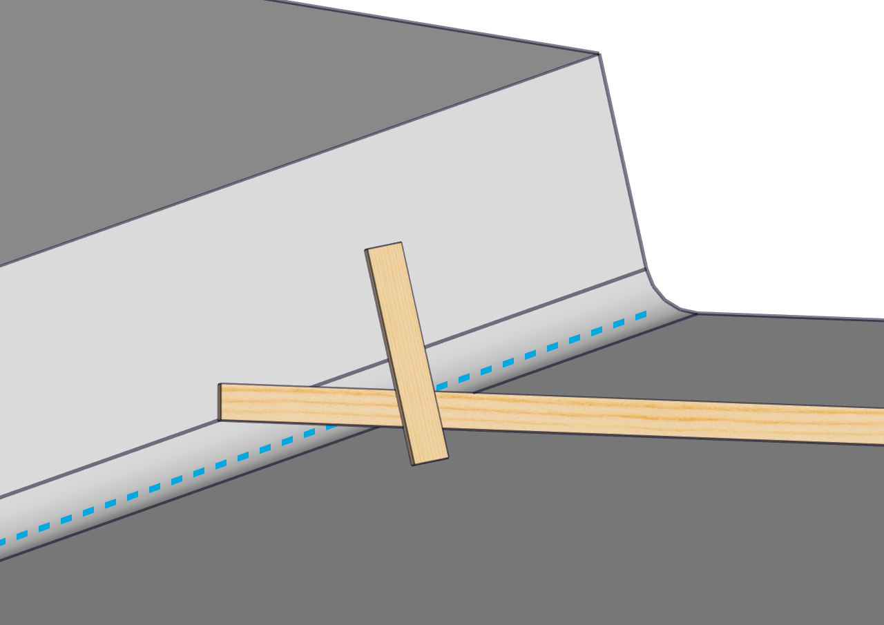
Figure 9 – Finding Reference Line with Straight Edges
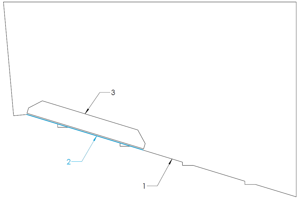
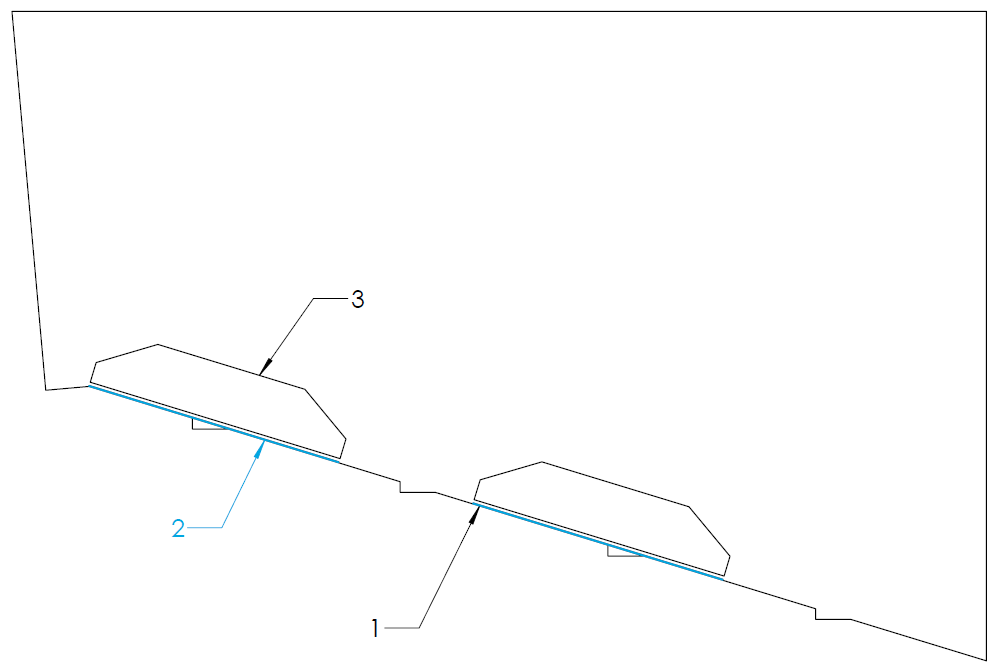
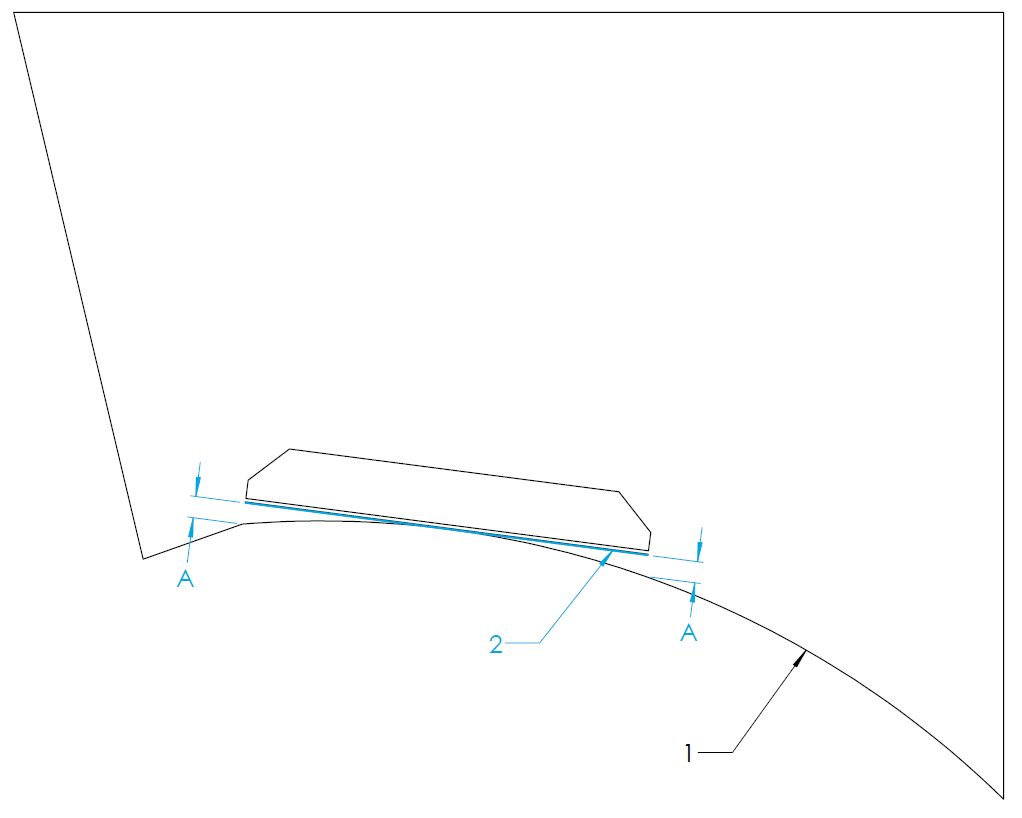
Figure 12 to Figure 19 in this section show a view from the stern of the vessel looking toward the bow. Label 1 indicates the bottom of the hull, Label 2 indicates the RRL, and Label 3 indicates the outline of the Transom Plate.
Strakes
Note: In this instruction manual the term ‘Strake’ is regarding a portion of the hull bottom which has an abrupt change in deadrise angle in comparison to the greater hull bottom. Sometimes referred to as ‘Lifting Strakes’ or ‘Spray Strakes’ it does NOT concern Chines.
For hulls with strakes, they can be ignored for the placement of the equipment and determination of the RRL. Strakes which extend all the way to the transom can reduce the authority of the Seakeeper Ride equipment. Terminating the strake at least 12 inches forward of Ride maintains full system authority.
Concave and Convex Deadrise
The Seal Plates (Item Number 2 in Figure 5) have a straight design. Some hulls may have curvature along the deadrise which will cause the Seal Plate to show gaps between the deadrise at either the ends or center of the plate. The following sections describe how to find the RRL in concave and convex deadrise hulls.
Concave Deadrise
For vessels with concave curvature, the Seal Plate should be mounted such that the center of the Seal Plate is flush to the hull bottom and the ends of the Seal Plate are equidistant from the hull bottom (measurement A and B in the figures below). Measurement A and B must be 0.5 in. or less. More curvature decreases Seakeeper Ride Authority. For vessels with concave curvature, the RRL is defined as the tangent to the hull bottom, shown by the blue line.
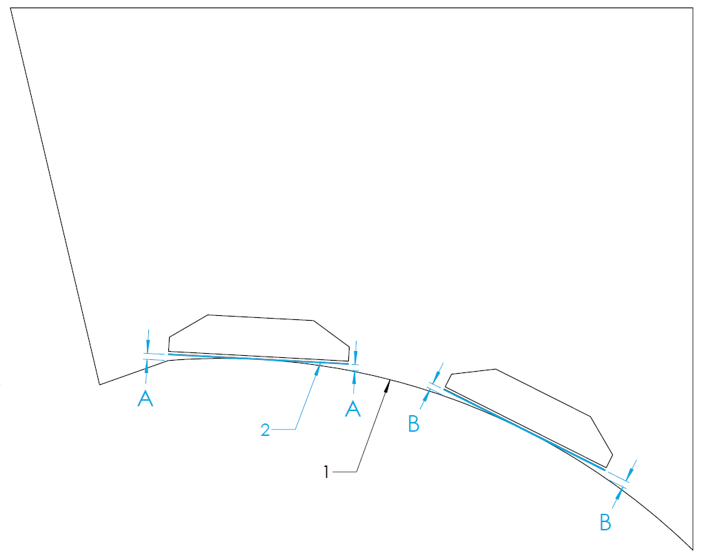
Convex Deadrise
For vessels with convex curvature, the ends of the Seal Plate should be mounted flush with the hull bottom with a gap between the center of the Seal Plate and the hull bottom (measurement A and B in the figures below). Measurement A and B must be 0.5 in. or less. More curvature decreases Seakeeper Ride Authority. For vessels with convex curvature, the RRL is defined as the straight line along the transom between inboard and outboard ends of the seal plate’s destination.
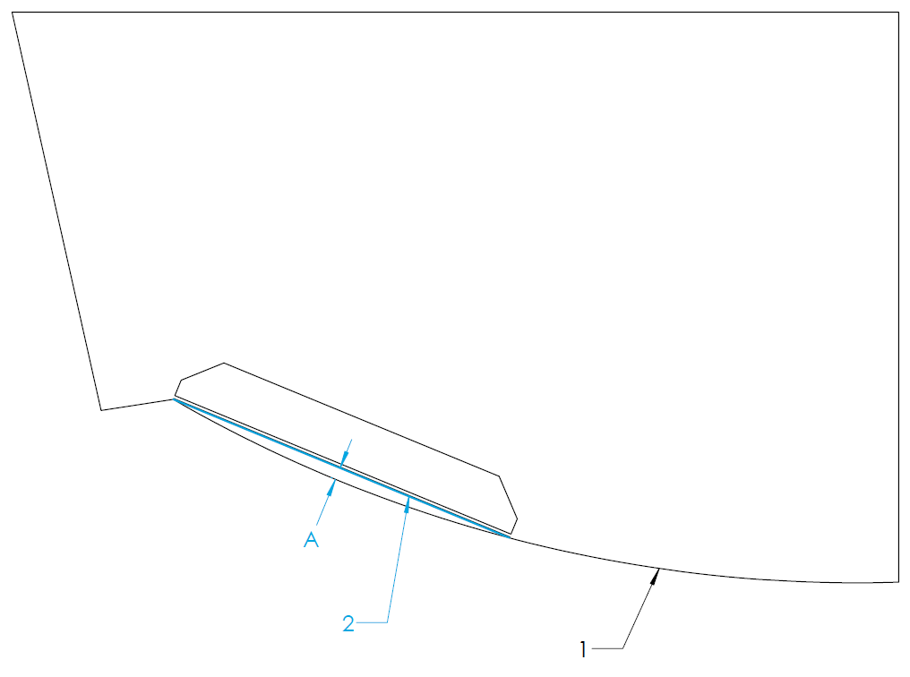
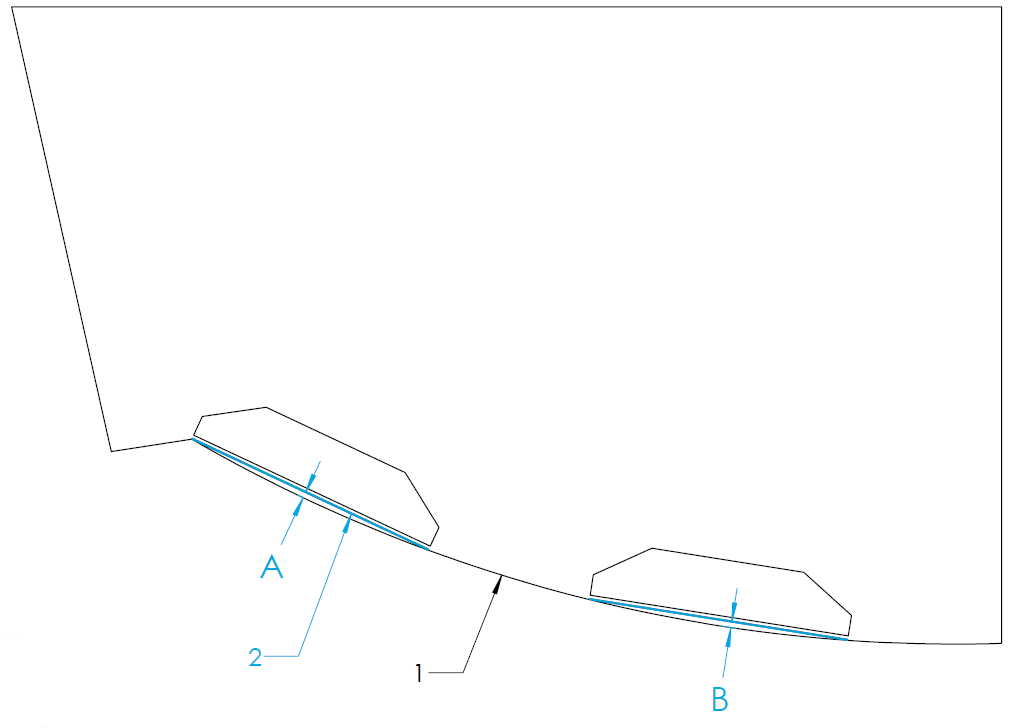
Figure 17 – Convex Hull Bottom RRL and Transom Plate Trace (Quad Controller)
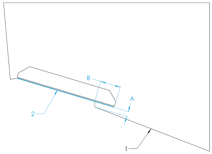
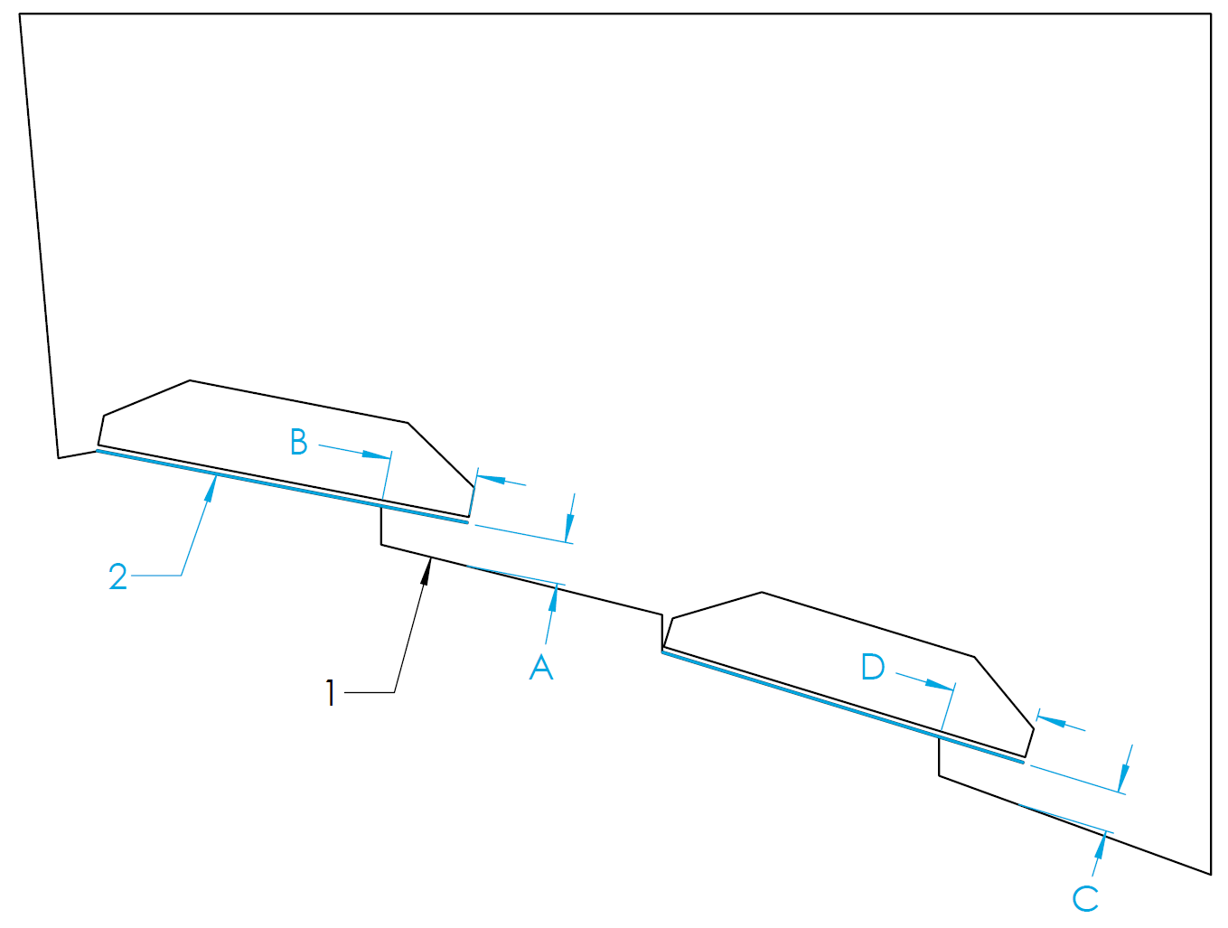
Variable Deadrise
Variable deadrise hulls are those where the running surface has breaks that run longitudinally. Generally, these hulls have decreasing deadrise angle in each successive panel moving outboard from centerline. Seakeeper Ride Controllers are capable of being mounted on variable deadrise hulls, so long as the following mounting conditions can be met:
- Distance from inboard edge of the Controller to the running surface of the hull (Dimension A and C in the figures below) is 0.75 in. (19 mm) or less. This requirement only applies to vertical changes beneath the Controller.
- The portion of the Controller extending inboard of the deadrise break (Dimension B and D in the figures below) is 3 in. (76 mm) or less. For Quad Controllers, the overhanging portion of both Controllers added together must be 3 in. (76 mm) or less (In the figure below, B + D = 3 in. max).
In hulls with a variable deadrise, the RRL is the highest portion of the deadrise that the Seakeeper Ride system will cover. See the figure below for this position. Because performance may degrade rapidly if these conditions are not met, please reach out to Seakeeper for guidance in this instance if a boat falls outside these parameters.
5.3 Beam-Wise Location
There are several hull features that should be considered when determining the location of the Controllers in a beam-wise orientation.
As a general rule, the OUTSIDE MOST Controllers must be mounted as far outboard as possible, up to the chines (if the hull has chines). Details on the precise beam wise location is in the following sections.
Inboard Controllers should be mounted according to different priorities and should follow section 5.4.

ATTENTION: Mounting the OUTSIDE MOST Controllers towards the centerline of the boat reduces the leverage the system has on the boat and severely reduces roll performance.
Chines
Note: In this instruction manual the term ‘Chine’ is regarding the intersection of the hull bottom and hull side with an abrupt change in deadrise angle. This is sometimes referred to as ‘Reverse Chine’.
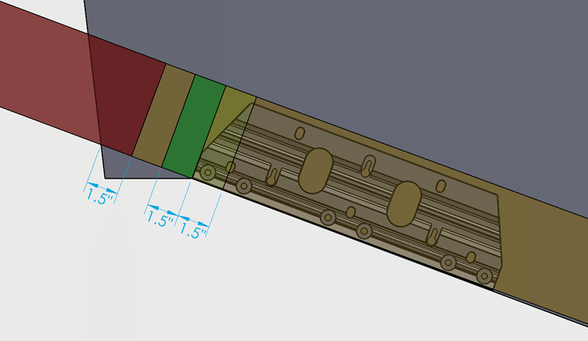
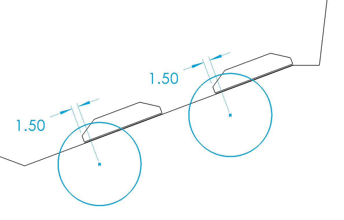
Based on the considerations of engine spacing and transom appendages, some installations will require the Controllers to extend outboard of the inboard edge of the chine. An overlap of the outboard chine of 1.5 in. (38 mm) is acceptable. For overlaps greater than 1.5 in. (38 mm), performance may degrade rapidly. The figure below illustrates placement of the outboard edge of the Controller with the following color code:
- Green (Outboard of chine up to 1.5 in. (38 mm)) – Ideal
- Yellow (Inboard of chine up to 1.5 in. (38 mm)) – Good
- Orange (More than 1.5 in. (38 mm) from chine) – Acceptable*
- Red (Overhanging Hull Side) – Unacceptable
*Controllers must NOT be mounted far enough inboard to reduce leverage, as outlined above.
Hull Side Spacing
It is possible to have an installation where the Controller is mounted too far outboard causing water flowing around the hull side to interfere with the Controller and substantially reduce performance.
To avoid this issue, the Controller should be mounted at least 1.5 in. (38 mm) inboard of the hull side, as shown below.
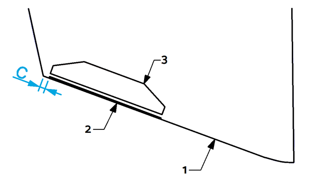
Figure 23 – Hull Side Clearance
Propeller Tunnels
In the event a hull has propeller tunnels and there is not enough beam to install a Dual Controller system outboard of the tunnel, it is possible to utilize a Quad Controller system.
The outboard controllers should be mounted outboard of the propeller tunnel.
The inboard controllers could be mounted in 2 locations. The inboard controller can be mounted on top of the propeller tunnel if there is a straight section of the tunnel to match with the controller seal plate. Alternatively the inboard controller can be mounted on the deadrise inboard of the propeller tunnel.
Review of other hull features like convex and concave hull bottoms and variable deadrise should be considered with this placement.
5.4 Engine Spacing
NOTE: For all installations it is vital to ensure the Ride equipment is mounted such that the propulsion equipment is able to articulate through its full range of travel including trim, tilt and steering without any contact between Ride and propulsion.
Inboard and Podded Propulsion Applications
For Inboard and Podded Propulsion boats where Ride is mounted aft of the propeller, the Ride mounting location should not take into consideration the propellers. Podded Propulsion includes but not limited to Mercury/Cummins Zeus Drive and Volvo IPS Drive.
Ride recommends utilizing Dual Controllers if the hull shape allows. In the event the hull has propeller tunnels or other novel hull features which prevent Dual Controller installation should consider Quad Controllers to allow best Ride authority over the hull. Testing has shown comparable performance in Dual and Quad Controller installations.
Outboard and Sterndrive (Inboard/Outboard) Applications
For Outboard and Sterndrive (I/O) applications the following guidance should be used to determine best locations for controllers relative to the propellers. Location must consider hull shape and propeller location in these boats.
NOTE: Seakeeper has performed successful testing with Seakeeper Ride overlapping propellers significantly further than indicated below; however, because of the infinite variables (engine height, engine trim, engine longitudinal offset from Seakeeper Ride Controllers, propeller selection, propeller rotation, sea conditions, loading conditions, vessel characteristics, and more) which impact the interaction between Seakeeper Ride and propulsors, Seakeeper cannot provide more specialized guidance or blanket recommendation to install with more propeller overlap than indicated below. If the Builder, Owners, or Operators choose to install the Seakeeper Ride Controllers with more propeller overlap than indicated in the figure below, it may result in rpm/coolant fluctuation and/or engine faults. Please see the Operation Manual for additional detail on Seakeeper Ride’s potential impacts to propulsors.
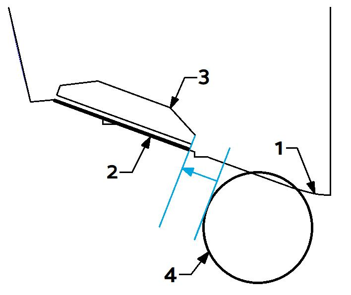
Due to the Controllers potential to change water flow into the boat’s propellers, it is recommended the Controllers be spaced around the engines and propellers to the outboard most Controllers should be mounted as far from the propellers as possible. It is recommended that the inner edge of the Controller be mounted outboard of the diameter of the propeller tip (see the figure below). The line defining this instruction is the tangent line to the diameter of the propeller tip on the outboard side, perpendicular to the deadrise. Label 4 indicates the diameter of the propeller tip.
5.6.1 Three (3) Outboard or Sterndrive Engine Applications
For installations with Triple Outboards or Sterndrive (Inboard/Outboards (I/O)) we recommend the following guidance for locating the controllers:
Dual Ride Controllers on three (3) Outboard or Sterndrive Engine Applications
If Dual Controllers are selected, the controllers should be mounted as far outboard to the hull side as indicated in Section 5.3.
Quad Ride Controllers on three (3) Outboard or Sterndrive Engine Applications
If Quad Controllers are selected, the outside controller to be as far up the chine as possible.
The inside controller is to be centered between the engines. If there is Controller overlap of propellers, the inside controller should be such that the Blades of all four (4) controllers overlaps of all three (3) propellers evenly.
5.6.2 Four (4) Outboard or Sterndrive Engine Applications
For installations with Quad Outboards or Sterndrive (Inboard/Outboards (I/O)) we recommend the following guidance for locating the controllers:
Dual Ride Controllers on four (4) Outboard and Sterndrive Engine Applications
If Dual Controllers are selected, the controllers should be mounted as far outboard to the hull side as indicated in Section 5.3.
Quad Ride Controllers on four (4) Outboard and Sterndrive Engine Applications
If Quad Controllers are selected, the outside controller to be as far up the chine as possible.
The inside controller should be such that the Blades of all four (4) controllers overlaps of all four (4) propellers evenly. Measuring for this can be simplified by setting the the distance from the outboard engine centerline to the outboard controller centerline the same as the distance from the inboard engine centerline to the inboard controller centerline.
5.6.3 Five (5) Outboardor Sterndrive Engine Applications
For installations with Quint Outboards or Sterndrive (Inboard/Outboards (I/O)) we recommend the following guidance for locating the controllers:
Dual Ride Controllers on five (5) Outboard or Sterndrive Engine Applications
If Dual Controllers are selected, the controllers should be mounted as far outboard to the hull side as indicated in Section 5.3.
Quad Ride Controllers on five (5) Outboard or Sterndrive Engine Applications
If Quad Controllers are selected, the outside controller is to be centered between outboard propellers.
The inside controller should be such that the Blades of all four (4) controllers overlaps the center and middle propellers evenly.
5.5 Physical Space
Before beginning the installation, check that there is adequate space in the ideal location determined above. Some hulls may not have physical space for the installation of Seakeeper Ride. There may be some installations where brackets, lights, live well pickups, hull features, or similar components must be cleared or relocated to proceed with the installation.

Note: Seakeeper is not responsible for hull modifications performed when attempting to install Seakeeper Ride. It is the responsibility of the installer to determine reasonable modifications to prepare room for the Controllers without making undesirable changes to the boat. If unsure of installation details, contact a licensed marine engineer or naval architect before making significant boat modifications. Contact Seakeeper if additional help is needed.
The width of the Controller mounting footprint will vary depending on Controller size. See the figure and table below for dimensions to determine if there is adequate space on the boat’s transom. The clearance between the bottom of the hull and any surface above where the Controller will be placed is recommended to be at least 5 in. (127 mm). The exact height is dependent on the transom angle and resulting Wedge Pack build of the Controller. The Controller will extend aft of the hull by 8 in. (203 mm).
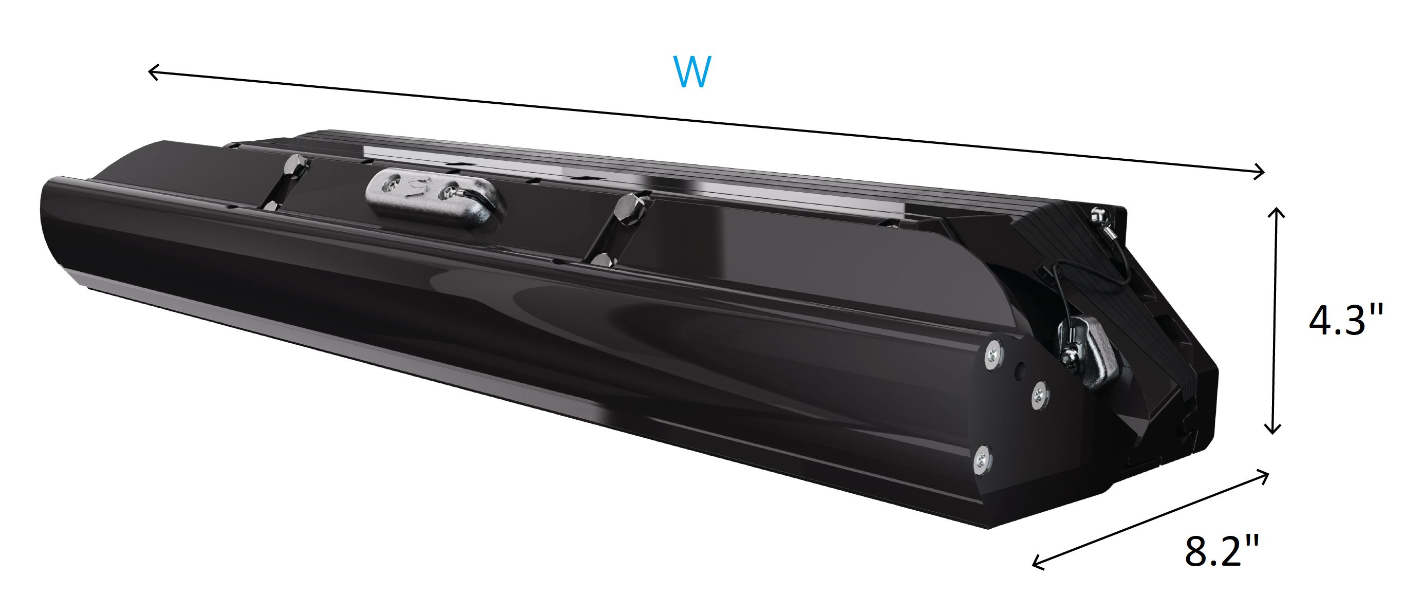
| Boat Length (ft) | 37-42 | 37-42 |
| Seakeeper Ride | 750 Dual | 750 Quad |
| Part Number | 90900 | 90882 |
| Width (mm) | 750 | 375 |
| Width (in.) | 30.1 | 15.4 |
Table 2 – Controller Width
Refer to the Controller Footprint and Envelope page for higher detail dimensions.
5.6 Loading and Storage Details
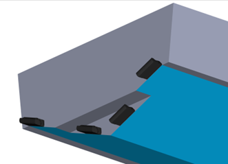
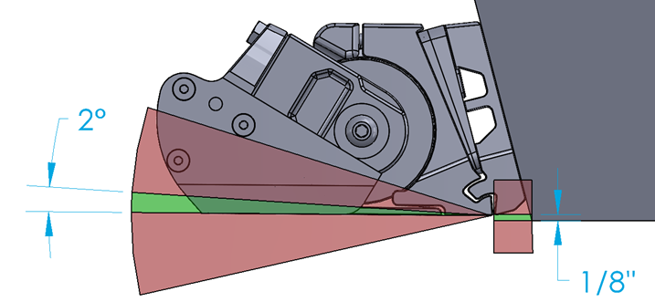
The Controllers should not be installed where they will carry any load of the boat while on bunks (i.e. a trailer, storage rack, or fork truck). If there is concern with bunks loading the Controllers:
Mount Upward – Seakeeper Ride can be mounted up to 1/8 in. (3.2 mm) up from the bottom of the hull with negligible effect on system performance.
Angle Upward – Seakeeper Ride can be mounted up to two (2) degrees angled upward from the bottom of the hull with negligible effect on system performance.
One or both of these mounting tolerances may be used to keep Seakeeper Ride from contacting the bunks and increase the longevity of the system.
Seakeeper Ride will automatically retract the Blades when coming to a stop, meaning that they will be flush with the rest of the Controller and should not cause problems when placing the boat on bunks during normal operation in both Auto and Manual modes.
Setting Up the Trailer for Seakeeper Ride
Cut bunks short – If the bunks are too long, cut them to correspond with the end of the transom rather than extending aft.
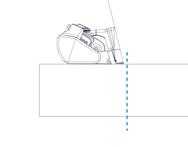
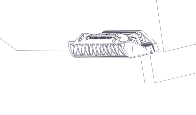
Figure 29 – Cutting Bunks Short
Cut bunks low – If the bunks cannot be cut shorter, bunks can be cut with a small recess below Seakeeper Ride to prevent excessive force on the Controller when going down the road.
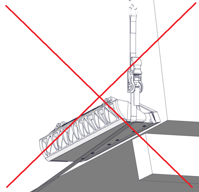
Do Not Place Tie-Down Straps Across Seakeeper Ride – Consider moving straps to cleats or to a different tie down point.
5.7 Asymmetrical Details
Many boats are not perfectly symmetrical about the centerline, resulting in subtly different mounting locations and angles for each Controller. This is acceptable and may require different Wedge Plate angles used for port and starboard Controllers. Following this guideline for the correct installation location will result in a proper installation even if there are asymmetries in the hull.
5.8 Cable Entry
In the final details of the installation, the cable that powers and drives the Controllers must pass through the transom of the hull. The location for cable penetration will be based on available access to the transom on the interior.
Concealed Cable Entry
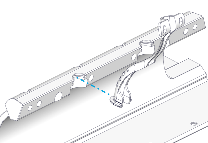
For concealed cable entry, route through either of the oval holes of the Transom Plate (highlighted in blue in the figure below). To utilize either location, you must be able to reach the hole from the inside to tighten the supplied cable gland and prevent water entering the hull.
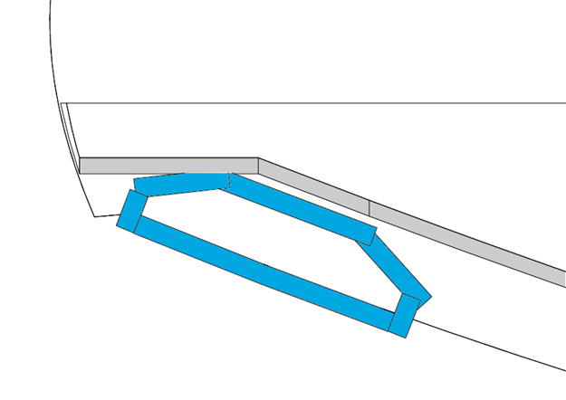
As an example for internal routing, the figure below depicts a stringer shown with dotted lines that is preventing use of the inboard cable penetration. In this example, the outboard cable pass-through is available as indicated by the blue arrow. This can only be used if there is access on the interior side of the penetration.
Exposed Cable Entry
Locations outside the Transom Plate can be used as well. If the cable penetration location is below the waterline, the supplied cable gland must be used to ensure a watertight hull after the penetration.
This cable penetration method can be used in locations above the waterline as well.
Cable Lengths
In all cases, the supplied cable for the Controllers is limited to 10 ft (3 m). Carefully consider the cable routing and location of the Distribution Module to ensure both cables can connect to the Distribution Module.
Note: On 4 controller applications, there are 2 distribution modules. Any Controller may be connected to any Distribution Module and function correctly. It is therefore possible to have a ‘Port Side Distribution Module’ and ‘Starboard Side Distribution Module’ or an ‘Inside Most Distribution Module’ and ‘Outside Most Distribution Module’ depending on available space and cable lengths.
6. Measure Transom Angle
Measure Transom Angle Introduction
Seakeeper Ride Controllers must be mounted as close to flush and parallel with the running surface of the hull as possible, as explained in Section 5. This portion of the installation requires installer to measure the transom angle at the chosen Controller locations.
The Ride 750 Series controllers allow for some adjustment in seal plate angle after installation to fine tune the equipment. We strongly recommend attempting to install the equipment as precisely as possible to achieve a flush and parallel Seal Plate. If the Seal Plate angle needs to be adjusted after adhesive cure it can be done.
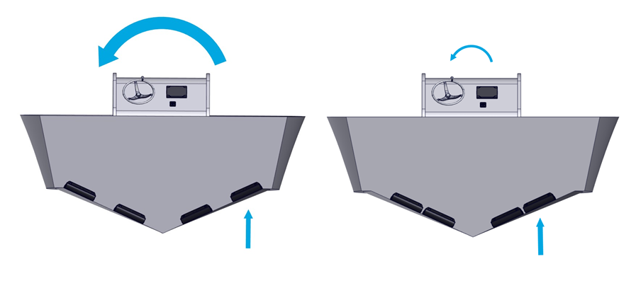
The Wedge Pack Assembly (Items 4, 5, 6, 7, and 8 in Inventory Parts) allows for the adjustment of the Controllers to the boat’s transom angle. The figure below illustrates the differences in the angle between the aft end of the running surface and the transom (A) and the resulting effects on Wedge Pack selection (B). The top two images show correct angle adjustments. The bottom two images show incorrect angle adjustments.
For optimal performance, the Seal Plate must be completely flush with the aft end of the running surface of the boat, which will eliminate angle C in the figure above. The Seal Plate can angle upward up to 2 degrees with a negligible effect on system performance. DO NOT mount the Controller angled upward more than 2 degrees. DO NOT mount the Controller angled downward at all.
6.1 Measurement Steps
- Using the selected Controller locations from Section 5, measure the angle with a digital protractor from the running surface to the transom, perpendicular to the deadrise. See the figure below for an example of the measurement on the port Controller, outboard location.
- Measure the inboard and outboard ends of the port 1 Controller area and use the larger angle in the following Sections. Round up to the nearest degree.
- Measure inboard and outboard ends of the starboard Controller area and use the larger angle in the following Sections. Round up to the nearest degree. As with every step, repeat measurement process for both port and starboard sides. Note: It is possible to find different angles between port and starboard side of the hull.
- For Quad Systems
- Measure the inboard and outboard ends of the port 2 Controller area and use the larger angle in the following Sections. Round up to the nearest degree. Note: It is possible to find different angles between port 1 and port 2 locations.
- Measure the inboard and outboard ends of the starboard 2 Controller area and use the larger angle in the following Sections. Round up to the nearest degree. Note: It is possible to find different angles between starboard 1 and starboard 2 locations.
5. Determine the number of Wedge Plates required for each Controller’s Wedge Pack using the transom angle measured previously and Table 3.

The transom and Wedge angles indicated in the Table 3 are the maximum range of the product. If the boat’s transom angle is outside the range of Table 3, do not add or remove more Wedges to accommodate the different angle. Contact Seakeeper to determine the best course of action.
Table 3 – Transom Angle and Wedge Plates
| TRANSOM ANGLE | 3 DEGREE | 4 DEGREE | 5 DEGREE | Top Bolt | Bottom Bolt |
| 90 | 3 | 1 | 2 | 75MM BOLT LENGTH | 40mm BOLT LENGTH |
| 91 | 3 | 2 | 1 | ||
| 92 | 1 | 2 | 2 | ||
| 93 | 2 | 1 | 2 | ||
| 94 | 3 | 2 | |||
| 95 | 3 | 1 | 1 | ||
| 96 | 1 | 1 | 2 | ||
| 97 | 2 | 2 | |||
| 98 | 2 | 1 | 1 | ||
| 99 | 2 | 2 | |||
| 100 | 1 | 2 | |||
| 101 | 1 | 1 | 1 | 55mm BOLT LENGTH | 35mm BOLT LENGTH |
| 102 | 2 | 1 | |||
| 103 | 2 | 1 | |||
| 104 | 3 | ||||
| 105 | 1 | 1 | |||
| 106 | 1 | 1 | |||
| 107 | 2 | ||||
| 108 | 1 | ||||
| 109 | 1 | ||||
| 110 | 1 |
6.2 Hulls with Unique Stern Features
For many planing hulls, the aft portion of the running surface is straight, however, there can be exceptions where there is a curvature, angle, or twist just forward of the transom. This may be referred to as a stern wedge, hook, or rocker. These types of features are generally added to the hull to improve handling characteristics or induce a constant trim, adding a bow down moment during normal running conditions.
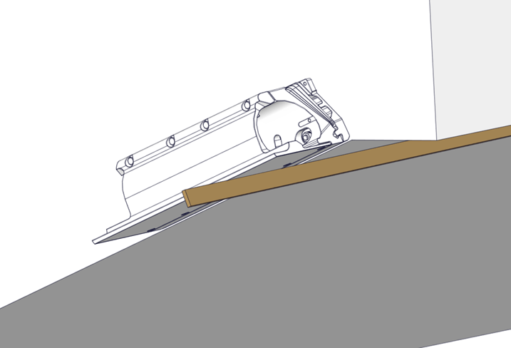
Be sure to use a 3-ft (0.9 m) straight edge along the hull bottom when evaluating the transom angles to obtain a correct assessment of the running surface.
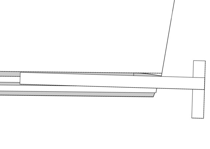
If the Seal Plate were to be installed following the same angle as a stern wedge, it would create a permanent additional upward force in the aft of the boat, and the bow would be pushed down irreversibly. This incorrect assessment for installation is demonstrated below.
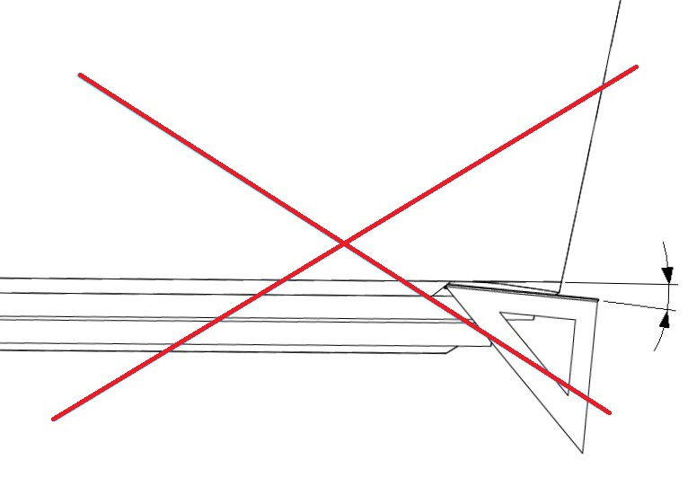
Measure the angle of the transom over a greater length of the running surface up to 3-ft (0.9 m) to ensure the proper angle.
7. Prepare Wedge Pack Introduction
Preparing the Wedge Pack Introduction
This portion of the installation will require the Wedge Pack hardware kit illustrated in Section 4.
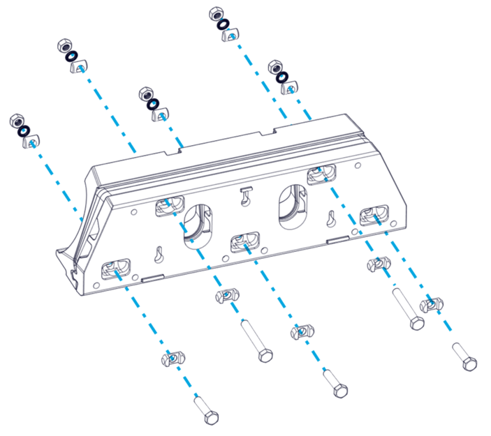
To begin the Transom Plate must be assembled. This requires selecting the correct length bolts as indicated by the transom angle table above.
- Place a Cylindrical Washer for Hex Head on each bolt, with the flat side on the head of the bolt.
- Install the bottom five (5) M8 bolts must be selected based upon the total Wedge Plates in use. See Table 2 to determine if the 35mm or 40mm bolts must be used. (The Quad controller systems will have three [3] bolts.)
- The top four (4) M8 bolts must be selected based upon the total Wedge Plates in use. See Table 3 to determine if the 55 mm or 75 mm bolts must be used. (The Quad controller systems will have two [2] bolts.)
- At this point, the bolts must be inserted into the Transom Plate with Cylindrical Washer for Hex Head cylinder in each of the 9 locations. (The Quad controller systems will have five [5] locations.)
- Cover the bolt head with the supplied self adhesive backed plastic caps. The caps will prevent adhesive leak by around the bolts and allow for tuning the equipment by adding or removing wedges once installed and adhesive has cured.
7.1 Determine Wedges to use for the Seakeeper Ride 750 system
Based on Table 3 and the transom angle determined in Section 6, compile the Transom Plate, Actuator Plate, Wedge Pack Hardware kit and appropriate wedges for each controller. It is possible that the hull has different angles for each Controller location.
- Stack the proper number of Wedge Plates on top of the Transom Plate using the bolts to guide them into place. The locking tabs of the Wedge Plates will face the Transom Plate and secure the correct orientation.
- Place the Actuator Plate on top of the Wedge Plates using the bolts to guide them into place. The tabs of the Actuator Plate will match with the grooves of the Wedge Plates to complete the Wedge Pack Assembly.

7.2 Secure Actuator Plate
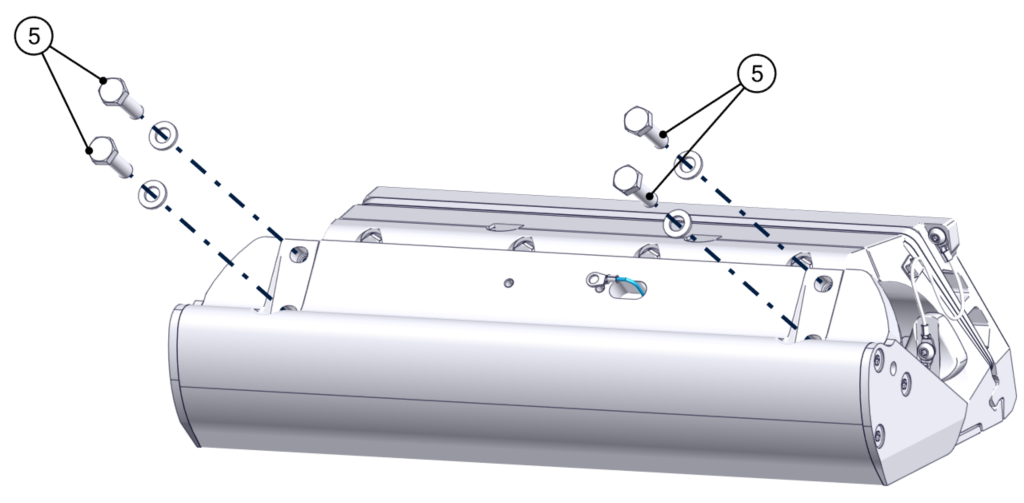
- Locate the following pieces:
- Qty 9 M8 Cylindrical Washers (Qty 5 per Controller on Quad Systems)
- Qty 9, M8 Wedge Lock Washers (Qty 5 per Controller on Quad Systems)
- Each washer has 2 components.
- Qty 9, M8 Nuts (Qty 5 per Controller on Quad Systems)
- Each washer has 2 components.
- Insert all the cylindrical washers, flat face out, onto each of the bolts within the milled pockets on the Actuator plate.
- Insert all the wedge lock washers onto each of the cylindrical washers.
- Thread all the nuts onto each of the bolts of the assembly hand tight.
- Check the bolt length is sufficient to engage all threads of the nuts.
- Tighten nuts to 130 in-lbs (14.7 N-m)
- Adhere Bolt Covers.
Note: Be sure to use the correct bolt length. Incorrect bolt length may result in insufficient thread engagement or the inability to attach the Seal Plate in later steps.
Note: All variables to be torqued to in-lbs NOT ft-lbs.
Repeat this process for all Controllers to create the Wedge Pack Assemblies before moving on.
8. Prepare Hull
Prepare Hull Introduction
Note: In Section 8 there are different levels of abrasion recommended to the installer based upon the history of the boat and materials used. Follow all steps 1 through 4 in preparation no matter what the abrasion requirements.
For fiberglass construction with original, unmodified gel coat follow Section 8.5.
For fiberglass construction where the history of the laminate is unknown, or where modifications or repair to the laminate have occurred follow sections Section 8.6.
When utilizing Epoxy adhesives follow Section 8.6.
For Aluminum construction follow Section 8.7.
8.1 Trace Template Outline
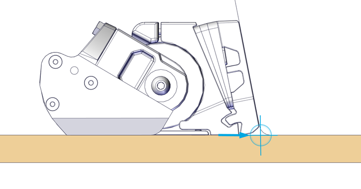
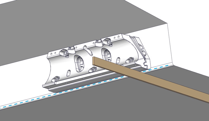
Figure 42 – Wedge Pack Assembly in Line with RRL and Hull Bottom
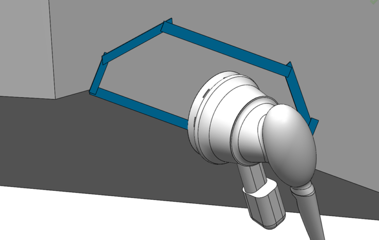
Based on the selection criteria from Section 5 for mounting location, hold the Wedge Pack to the transom in the designated location. Use a straight edge to align the Actuator Plate with the RRL (shown in blue above) and the bottom of the hull. Two people should be available for this section to make holding and tracing easier and more consistent.
For optimal Seakeeper Ride performance, the Seal Plate must be between the RRL and 1/8in. up above the RRL. DO NOT mount the Seal Plate below the RRL at all. If trailering or forklifting the hulls are a frequent occurrence, it may be desirable to mount the equipment 1/8in up to avoid excess contact with the trailer bunks or forklift. Alternatively moving bunks or forklifting the hull in a different location to avoid contact can be done to maintain peak performance.
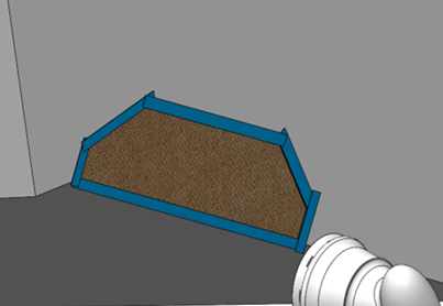
- Using a marker or pencil, trace the outline of the Transom Plate on the transom.
- Trace three (3) mounting hole (keyhole) locations while the Transom Plate is in place.
- Trace out cable entry oval holes.
8.2 Drill Holes
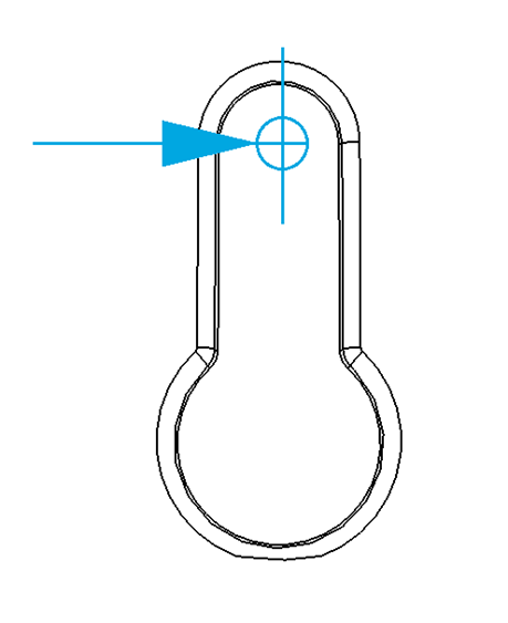
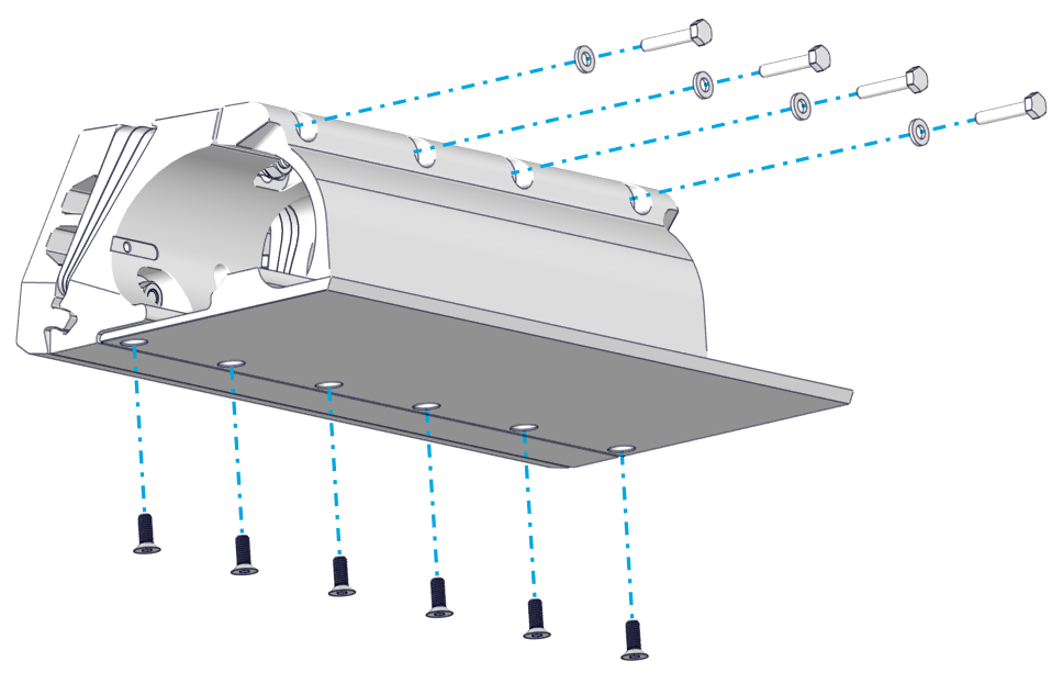
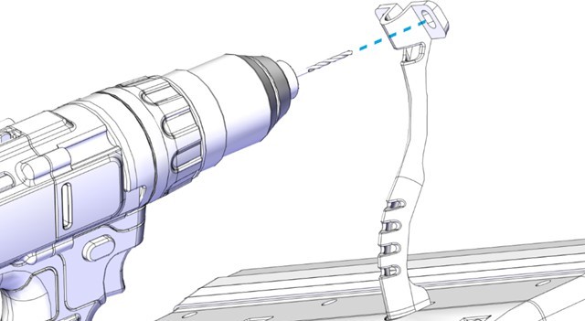
- Drill pilot holes for each of the three (3) positioning screws highlighted in the figure below using a 9/64 in. (3.6 mm) drill bit. The screws will be installed such that they are extending off the transom approximately 3/4 in. (19 mm). Drill the holes at the highest available position of the keyhole slot, as shown below.
- For aluminum hulls it is possible to utilize machine screws to support the transom plate as prepared for in this step. If you wish to use machine screws, drill and tap these holes at this time and locations indicated in this step.
8.3 Wipe Area with Solvent
Using denatured alcohol and a plain white paper towel, wipe the area down to remove surface contaminants.
8.4 Mask Area with Tape
Mask the area surrounding the Transom Plate with tape to protect the surrounding gelcoat or paint, as shown below. Mask all surfaces below the Ride Reference Line, such as spray strakes.

8.5 Fiberglass Hulls – Abrading Gel Coat
Note: This section is only for new build installations at the boat original equipment manufacturer (OEM) or for boats that meet the following criteria:
- Purchased directly from the OEM.
- Less than 6 months old.
- Known history with virgin gel coat. The boat must never have been painted, repaired, or modified in any way.
If the boat does not meet these requirements, or if there is any uncertainty, follow Section 8.6.
Sand down the gel coat with 60 grit sandpaper to remove the gloss surface. You may use a Dual Action Sander (DA), but you must be extremely careful not to remove excess material. Note: It is important not to change the shape of the transom and to stay within the perimeter of the Transom Plate.
8.6 Fiberglass Hulls – Removing Gel Coat
Note: Follow this section for most refit installations. If the boat does not meet the criteria listed below in Section 8.5, or if there is any uncertainty, continue with this section. Seakeeper requires this level of preparation when using epoxy adhesives based on endurance testing of the adhesives.
If the transom in question has been repaired or modified in any way that would compromise fiberglass bond in the region of the Controller installation, please contact a structural engineer or naval architect to ensure the structure in way of the Controller is suitable for installation. If the structure is deemed acceptable for installation, continue through the following sections.
Grind the area where the Transom Plate is to be mounted, using 60 grit abrasive pad or Dual Action Sander. Remove the outer layers of paint, gel coat, or fairing to reveal the fiberglass beneath.
Note: Be sure to wipe the sanded down area with denatured alcohol to allow for a clean space before adhesive is used.
8.7 Aluminum Hulls
For aluminum hulls, use 80 grit sandpaper, a grinder, wire brush or a Dual Action sander to scuff the entire mounting surface to remove all coatings and oxidation until the Seakeeper Ride Controller area is a rough surface with no impurities for the approved two-part adhesive to adhere to. For aluminum hulls be sure to follow adhesive manufacturers recommendations for surface preparation and application of adhesive.
8.8 Insert Positioning Screws
If installing on a fiberglass Hull, insert the No. 8 x 1.5 in. positioning screws, leaving the head exposed off the hull by about ¾ in. or 19mm. For Aluminum hulls, wood screws may be substituted with self- taping screws or machine screws if a drill and tap are utilized.
Note: These positioning screws provide no structural purpose and will not support the weight of the Actuator. These screws are intended to assist with installation only and are not meant to handle any forces created by the Controller.
9. Test Fit
Test Fit Introduction
To ensure proper fit of the equipment, the Seal Plate must be temporarily installed.
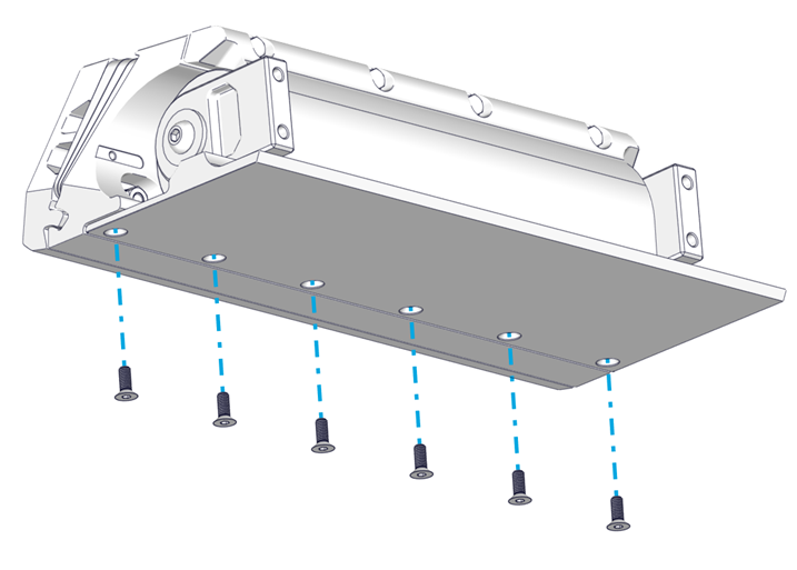
9.1 Test Fit the Seal Plate
- Hang the Wedge Pack on the positioning screws. Align the bottom surface of the Wedge Pack Assembly with the deadrise as indicated in Section 5.
- When aligned, tighten the positioning screws to hold the Wedge Pack in place.
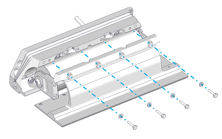
- Thread in two (2) of the bottom six (6) M6-1.0 x 16 mm Flathead Screws to align the Seal Plate with the Wedge Pack Assembly, but do not tighten. See figures below.
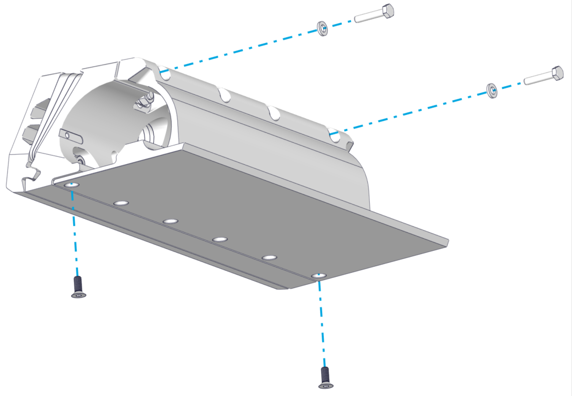
Figure 52 – Seal Plate Test Fit
- Thread in two (2) of the top four (4) M6-1.0 x 30 mm Hex Head Bolts with M6 Washers to align the Seal Plate with the Wedge Pack Assembly, but do not tighten. There should be a gap between the top of the Seal Plate and the Wedge Pack Assembly.
- Using a straight edge, verify that the Seal Plate is in the position identified in Section 5. Due to different hull shapes and features, the Seal Plate may not be flush with the hull bottom across its full span. However, make sure no part of the Controller is below the RRL. For more information, refer to Section 5.
- If the Seal Plate is not flush in the location needed, repeat Section 7, modifying the number of Wedge Plates until the correct angle has been achieved. Note: When removing and re-inserting bolts, be cautious of debris on the hardware that can cause it to bind, including old thread locker, dirt, etc.
- Once fit is satisfactory, mark the alignment with a writing utensil on inboard and outboard sides of the Transom Plate to make the final mounting easier.
- Remove the Seal Plate from the Wedge Pack.
10. Drill for Cable Entry
Drill for Cable Entry Introduction
The Seakeeper Ride system can be installed on a variety of boats with different space and size constraints for the Actuator Cable entry. Based on the selection of cable entry determined in Section 5.8, follow either Section 10.1 for Concealed Cable Entry or Section 10.2 for Exposed Cable Entry.
10.1 Concealed Cable Entry
The cable routing can be concealed if the hull structure allows for it. Follow this procedure for mounting the supplied protective conduit for the Actuator cable.
- Check for available space on the interior of the hull and clean access to the transom prior to starting the Concealed Cable Entry procedure. Verify there is no structure or cable in the way of either inboard or outboard oval hole location of the Wedge Pack Assembly.
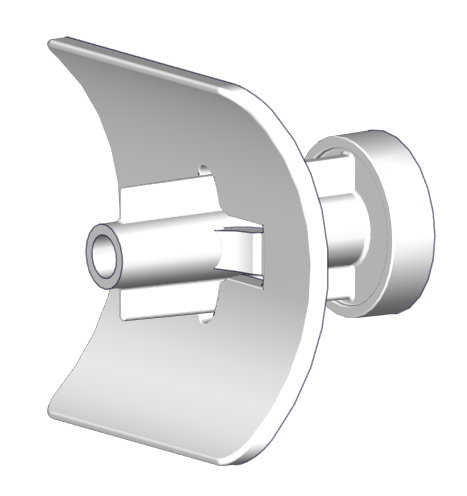
- Assemble the Drill Guide by placing the Drill Guide Tube inside of the follower with the rounded part of the tube on the outer diameter of the follower, as shown below. The tube should telescope in and out of the follower freely.
- Leave the Wedge Pack in place as fitted during Section 9.
- Place the Drill Guide Assembly in one of the oval cable ports in the Wedge Pack Assembly as shown below.
- The inboard or outboard oval cable port in the Wedge Pack Assembly can be used depending on available inboard space.

- Press the face of the Drill Guide flush with the transom of the boat. Use this to create a 1/4 in. (6.4 mm) pilot hole in the transom.
- Remove the Drill Guide.
- Loosen the positioning screws that are holding the Wedge Pack in place, then remove the Wedge Pack Assembly.
- Drill out the pilot hole to match the diameter of the Cable Gland with a 3/4 in. (19 mm) drill bit.
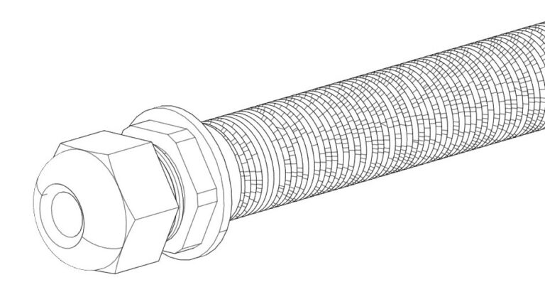
- Apply a liberal amount of sealant on the outer diameter of the Cable Gland tube (See below, Left). Install the Cable Gland tube from the inboard side of the transom.
- Apply more sealant where the tube meets the outboard side of the transom (See below 40, Right).
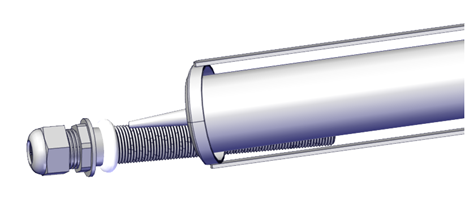
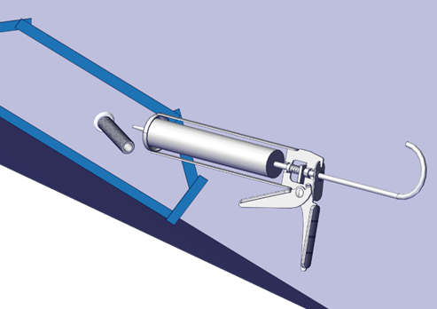
Figure 56 – Sealant Application to Cable Glan
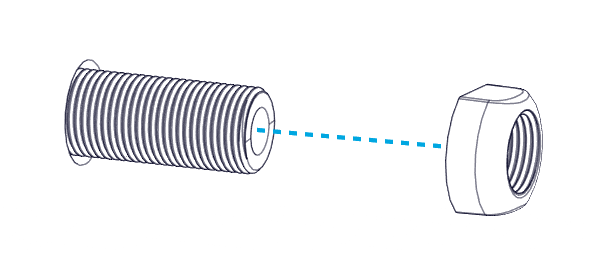
Install the Nut on the outboard side of the transom. Tighten until the Nut contacts the transom. Do not overtighten.
13. Cut off the excess threads on the outboard side off using a hacksaw or oscillating tool.
10.2 Exposed Cable Entry
In the instance in which the Actuator cable will be exposed, follow this procedure for mounting the supplied protective conduit for the Actuator cable.
- Check for structural clearances and rigging inside the hull before proceeding with drilling holes for the cable route in the transom.
- Determine the ideal location where the cable will penetrate the hull based on Section 5.7
- Using 3/4 in. (19 mm) drill-bit or hole saw, drill a hole through the transom.
- Apply a liberal amount of sealant on the outer diameter of the gland. Install the Cable Gland tube from the inside (Figure 56 – Sealant Application to Cable Gland).
- Install the Nut on the outboard side of the transom. Tighten until the Nut contacts the transom. Do not overtighten (Figure 57 – Outboard Cable Gland Nut Installation).
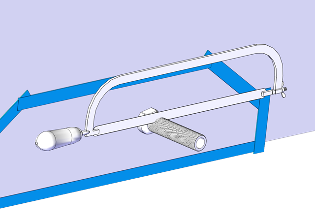
- Cut off the excess threads on the outboard side using a hacksaw or oscillating tool (Figure 58 – Cable Gland Trimming).
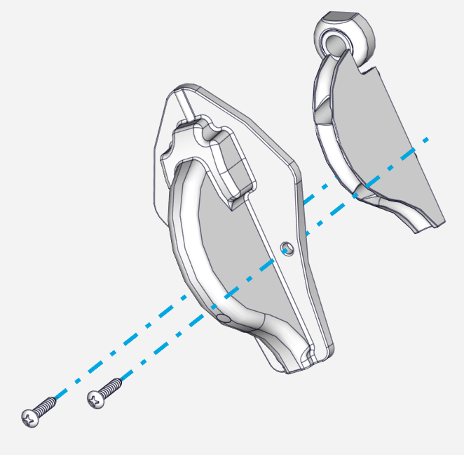
- Hold the Inner Cable guide up to the Cable Gland in the desired mounting location. Mark the locations of the two (2) mounting screws and drill 3/32 in. (2.4 mm) pilot holes in these locations.
- Inject sealant in both pilot holes. Use a screwdriver to install the two (2) No. 8 x 1-1/2 in. screws to mount the Inner Cable Guide.
11. Mount Wedge Pack
Mount Wedge Pack Introduction
Care must be taken to ensure clean working conditions. Wearing clean gloves is highly recommended to keep caustic substances off skin and prevent oil and grease from getting on adhesive surfaces.
For concealed cable entry, take note of the Actuator cable routing side. Knowing the routing side will be required when commissioning the system.
11.1 Prepare Parts and Hull
- Wipe the area to be bonded with acetone or denatured alcohol and plain white paper towels.
- Replace the tape around the border of the abraded portion of the transom where the Transom Plate will be mounted. Mask around the mounting location and the bottom of the boat. The tape will help keep the surrounding gelcoat clean of adhesive. The inside of the Cable Gland should be covered to avoid adhesive from entering the gland, particularly when installing with a Concealed Cable Entry as indicated in Section 10.1.
3. Tape the top, side, and bottom edges of the Wedge Pack Assembly. On the bottom, cover the gap between the Transom Plate and the Actuator Plate while leaving the angled portions of the Transom Plate exposed as shown below.
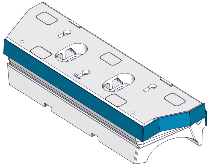
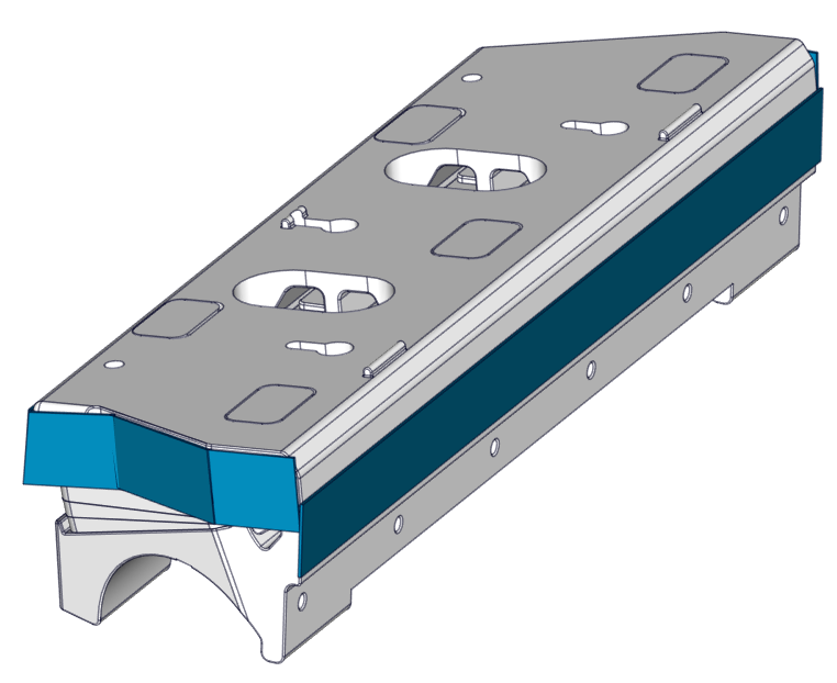
Figure 61 – Tape on Wedge Pack
4. Wipe the mounting face of the Wedge Pack down with denatured alcohol using plain white paper towels to remove oil/surface contaminants. The mounting face will show a matte grey color compared to the gloss black finish of the other parts in the kit. The mounting face has been masked off during the coating process to reduce assembly time.
Please note these solvents will distort the aesthetic quality of the gloss black parts if they spill. Careful application to the mounting surface should be used.
11.2 Clean Adhered Surfaces
- Wipe the Wedge Pack down with denatured alcohol and plain white paper towels a second time to remove oil and/or surface contaminants. Again, solvents will cause aesthetic damage to the coatings on parts, therefore be careful to only apply the wipe on the surface which is mounted to the boat transom.
- Clean the transom mounting location with acetone or denatured alcohol and plain white paper towels a second time to remove oil and/or surface contaminants after sanding.
11.3 Adhere Wedge Pack
- Apply adhesive to both the Transom Plate and transom. Use at least the amount of adhesive listed in the table below to ensure both surfaces are covered completely by adhesive. There must be enough adhesive between the Transom Plate and the transom for a strong bond with no voids. The Transom Plate has three (3) stand offs to allow for adequate adhesive thickness once mounted.
Please verify the adhesive selected from the approved list is compatible with your hull material. If in doubt, contact the adhesive manufacturer for best practice instructions with your given hull material. Some materials may require a primer for best adhesion. See here 3. Tools Needed – Seakeeper Manuals
Note: Work from this point on should be deliberate, keeping in mind the working time of the adhesive being applied. Warmer temperatures reduce working time.
Quantity:
| Controller Size | Minimum Adhesive Quantity (per boat) | Minimum Adhesive Quantity (per Controller) |
| 750 mm Quad | 1500 ml | 750 ml |
| 750 mm Dual | 1500 ml | 375 ml |
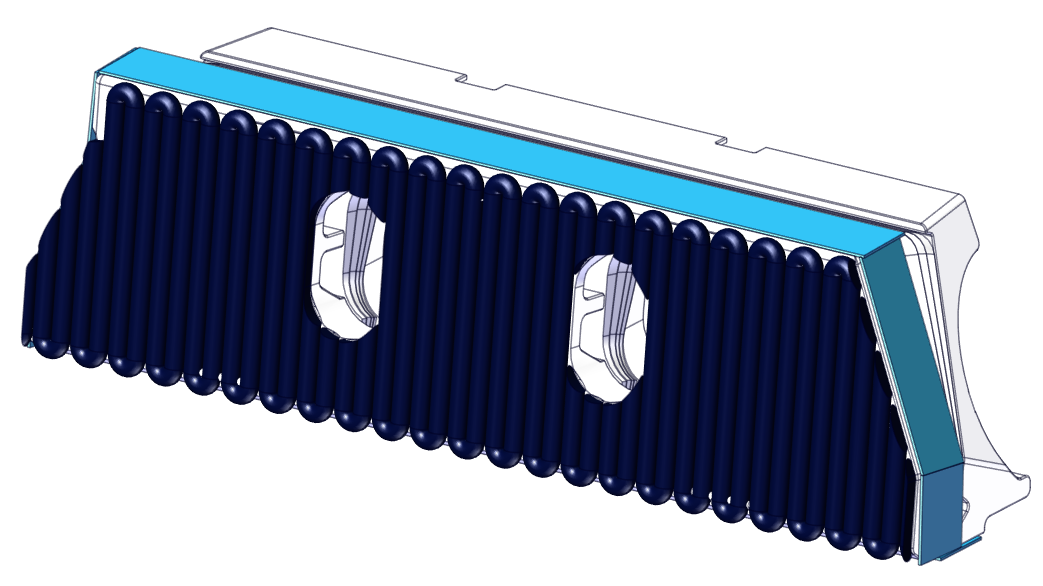
Figure 62 – Adhesive on Wedge Pack and Transom
2. . Install the Wedge Pack Assembly by sliding the keyholes over the positioning screws. Excess adhesive should appear around the entire perimeter of the Wedge Pack Assembly as the Wedge Pack is pressed into place.
11.4 Confirm Location
- Add the Seal Plate to the assembly to check its position as indicated in Section 9.
- Thread in the bottom six (6) M6-1.0 x 16 mm Flathead Screws, but do not tighten.
- Thread in the top four (4) M6-1.0 x 30 mm Hex Head Bolts with M6 Washers to align the Seal Plate with the Wedge Pack Assembly, but do not tighten. There should be a gap between the top of the Seal Plate and the Wedge Pack Assembly.
2. Using a straight edge, verify the Wedge Pack is flush with the hull bottom in the desired location as determined in Section 5. Be sure location requirements previously called out are met. Due to different hull shapes and features, the Seal Plate may not be flush with the hull bottom across its full span.
3. Once the position is confirmed, remove the Seal Plate, and tighten the positioning screws with a Phillips head screwdriver. The screws must be tight enough to press out excess adhesive and keep the assembly from sagging.
Note: In the uncommon case that the measured transom angles for the inboard and outboard sides of a Controller location (found in Section 6.1) are greater than 2 degrees apart, tighten beginning on the side with the larger transom angle pulling it tight to the transom. On the side with the smaller transom angle, gently advance the screws but do not tighten it all the way to the transom. If the screws on the side of the smaller transom angle are overtightened, it can stress the fasteners and cause issues.
11.5 Fair in Excess Glue
- Using a squeegee, putty knife, or tongue depressor, fill in the gap between the running surface of the hull and the Actuator Plate with excess adhesive, as shown below. Apply extra adhesive as needed. Note: The smooth transition from the hull bottom to the Seal Plate is critical for achieving the best performance out of the system.
2. Using a squeegee, putty knife, or tongue depressor, clean away excess adhesive.

ATTENTION: For concealed cable entry, clean out all of the adhesive from around the Cable Gland. You must make sure the Cable Gland will be accessible after the adhesive cures.
3. Make a smooth transition with adhesive on the upper edges of the Transom Plate to the transom. Apply extra adhesive as needed.
4. Remove the masking tape from the Wedge Pack Assembly and transom. If needed, clean any excess adhesive using denatured alcohol and plain white paper towels.
6. Allow adhesive to cure before proceeding. Some adhesives have ‘handling times’ where the product feels firm but is not ready for loading. Some adhesives also have required times before submersion. Please follow the adhesive manufacturer’s instructions.
7. For aluminum hulls, upon completion of the installation use a paint or similar coatings to protect the edges of aluminum from corrosion seeping between the adhesive and aluminum.
12. Actuator and Blade Installation
Actuator and Blade Installation Introduction
The final stages of installation are differentiated by the cable entry into the hull. If you are following a concealed cable entry, follow the procedure detailed in Section 12.1. For exposed cable entry, follow procedure in Section 12.2.
Note: Do not bend the Actuator Cable at a radius smaller than 50 mm (1.97 in.) to avoid damaging the cable.
12.1 Concealed Cable Entry
- Place the Actuator into the Actuator Plate, aligning the cable gland in the slot provided in the Actuator Plate. The Actuator can be mounted either way, so the cable is in the left or right slot. The arms should be pointed out toward the installer. One arm is stiffer than the other.
- Position the Seal Plate over the arms and Actuator and align the countersunk holes on the bottom surface.
- On Dual Controller systems the 2 supplied plastic debris caps will need to be inserted between the Seal Plate and Actuator Plate at this stage. See Figure 67 below.
- Apply thread locker and thread in the top four (4) M6-1.0 x 30 mm Hex Head Bolts with M6 Washers to align the Seal Plate with the Wedge Pack Assembly, but do not tighten. There should be a small gap (about 2 mm) between the top of the Seal Plate and the Actuator Plate. (Quantity six (6) bolts for Dual Controller systems)
- Visually center the Actuator to the Seal Plate by comparing small length of protruding Actuator housing on each end.
- Apply thread locker and insert the bottom six (6) M6-1.0 x 16 mm Torx Flathead Screws. Torque to 80 in-lbs (9 N-m) in an alternating pattern. Repeat the top torquing sequence 2 times or until the bolts do not rotate when achieving the torque. (Quantity ten (10) bolts for Dual Controller systems)
- Torque the top four (4) M6-1.0 x 30 mm Hex Head Bolts to 50 in-lbs (5.7 N-m) in an alternating pattern. Repeat the top torquing sequence 2 times or until the bolts do not rotate when achieving the torque. This ensures an even clamping force is applied across the Actuator. (Quantity six (6) bolts for Dual Controller systems).
- Ensure rubber gromet is present in Cable Gland and then Tighten the Cable Gland on the inboard side of the transom. The Cable Gland should be snug to prevent leaking, but do not overtighten. Gently pull on the cable to ensure there is no movement and prove it is sealing securely.
Verify Seal Plate Angle
At this point the Seal Plate angle can be verified with a straight edge to ensure the wedge pack selection was correct. Following the procedure from Section 6.2 to check the angle of the Seal Plate. If adjustments are desired, remove Seal Plate and rebuild the Wedge Pack following Section 7 in place until desired Seal Plate angle is achieved.
Note: The Cable Gland must have the rubber grommet in place to properly seal. The outside of the cable must be clean of debris, dust, adhesives, etc. to properly seal. Do not allow acetone to come in contact with the Controller Cable Gland Sealing Nut.
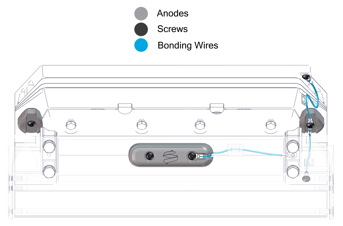
- Attach the bonding wires and Actuator Plate Anodes.
- Attach one terminal end of one bonding wire to the upper right corner of the Transom Plate using one (1) M2-0.7 x 6 mm Phillips Head Screw.
- Attach one terminal end of another bonding wire the the front right-hand side of the Seal Plate using one (1) M2-0.7 x 6 mm Phillips Head Screw.
- Install the two (2) Actuator Plate Anodes using two M5-0.8 x 20 mm Button Head Screws. Slide the two free terminal ends of the bonding wires over the right-hand anode screw while inserting creating a continuous connection between the Transom Plate, Actuator Plate, and Seal Plate.
- Note: Install the wire to the starboard side arm before mounting the Blade.
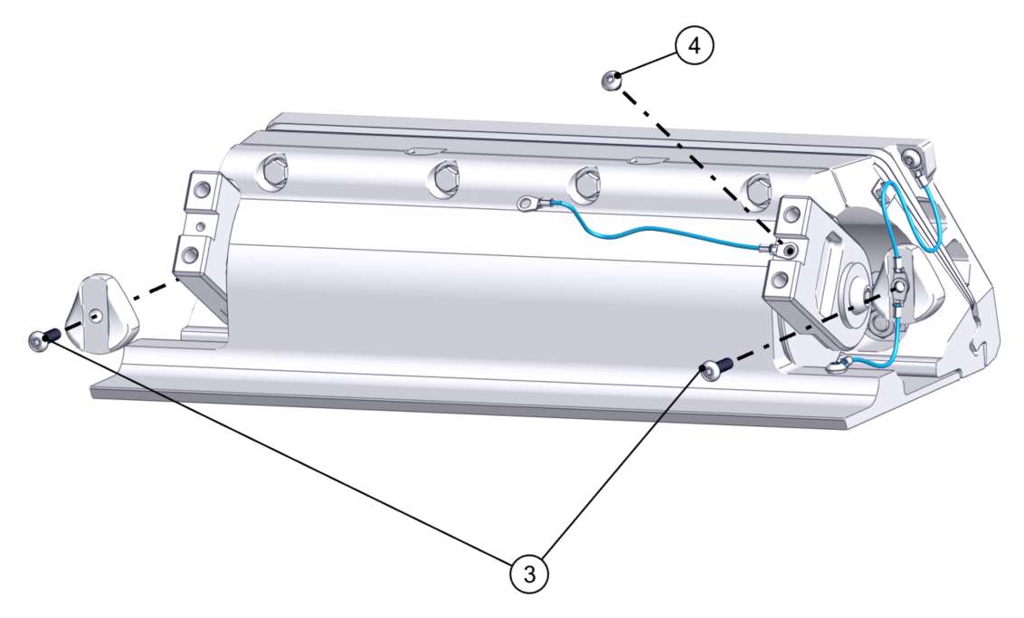
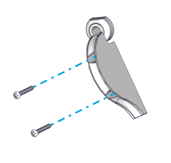
- Install the Blade to the Actuator Arms using the four (4) M8-1.25 x 30 mm Hex Head Bolts and their washers. Slide one of the bonding wire terminal ends over the top right bolt while inserting. Before torqueing the bolts, push the Actuator Arms firmly down against the Blade supporting edge. Torque these four (4) bolts to 130 in-lbs (14.7 N-m) in an ‘X’ pattern.
- Once installed, push the Blade all the way down and verify that the Blade is not contacting the Seal Plate. There should be a small, even gap between the Blade and the Seal Plate.
- Before torquing, the Blade can be slid up and down slightly to bring it closer and farther away from the Seal Plate, respectively. If the Blade is rubbing and creating friction against the Seal Plate, or if the gap appears too large, adjust the Blade accordingly. Contact Seakeeper if there are still concerns with Blade gap tolerance after following these instructions.
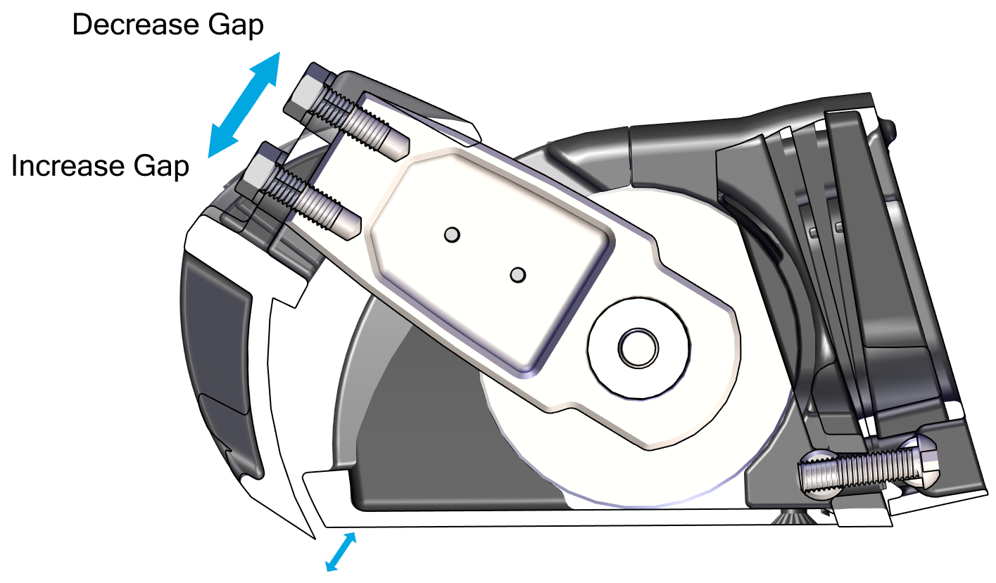
Note: Maintaining this gap between the Blade and Seal Plate is critical to maintaining factory tested failure mode performance. If the gap between the Blade and Seal Plate is too large, system performance will fall off. If the Blade contacts the Seal Plate, the friction will slow down the system’s response time, also reducing performance.
To maintain the factory fitment:
- Do not apply anti-fouling coating to the surfaces between the Blade and Seal Plate in order to avoid changing the fit of those parts.
- Always keep the surfaces between the Blade and Seal Plate clean and free from debris, including naturally occurring debris (such as marine debris) and other debris (such as paint or coating.
- When repairing or replacing any components on the Controller, confirm that the Blade rotates by hand. Resistance will be felt from the Actuator, but there must be no additional grinding or friction inhibiting movement.
- Install the Blade Anode using two M5-0.8 x 20 mm Button Head Screws. Slide the other terminal end of the bonding wire over the right-hand side screw while inserting.
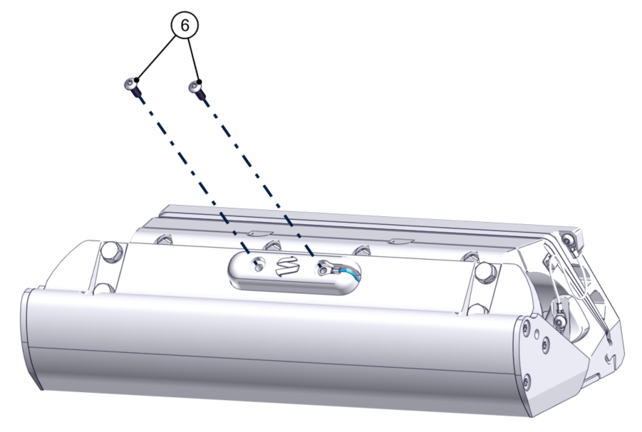
When complete, the anodes and bonding wires should be connected as shown below.
12.2 Exposed Cable Entry
- Install the Cable Guide Support in the groove in the Seal Plate.
- Place the Actuator into the Actuator Plate. The Actuator can be mounted with cable exiting to port or starboard side, so select the correct side to align with the Cable Guide. The arms should be pointed out toward the installer. One arm is stiffer than the other.
- Position the Seal Plate over the arms and Actuator and align the countersunk holes on the bottom surface.
- On Dual Controller systems the two (2) supplied plastic debris caps will need to be inserted between the Seal Plate and Actuator Plate at this stage. See Figure 67.
- Route the Actuator Cable through the Cable Guide Support.
- Apply thread locker and thread in the top four (4) M6-1.0 x 30 mm Hex Head Bolts with M6 Washers to align the Seal Plate with the Wedge Pack Assembly, but do not tighten. There should be a small gap (about 2 mm) between the top of the Seal Plate and the Actuator Plate. (Quantity six [6] for Dual Controller systems) See Figure 66 – Seal Plate Top Screw Installation.
- Visually center the Actuator to the Seal Plate by comparing small length of protruding Actuator housing on each end.
- Apply thread locker and insert the bottom six (6) M6-1.0 x 16 mm Torx Flathead Screws. Torque to 80 in-lbs (9 N-m) in an alternating pattern. Repeat the top torquing sequence 2 times or until the bolts do not rotate when achieving the torque (Quantity ten [10] bolts for Dual Controller systems) See Figure 69 – Bottom Bolts Installation.
- Torque the top four (4) M6-1.0 x 30 mm Hex Head Bolts to 50 in-lbs (5.7 N-m) in an alternating pattern. Repeat the top torquing sequence 2 times or until the bolts do not rotate when achieving the torque. This ensures an even clamping force is applied across the Actuator. (Quantity six (6) bolts for Dual Controller systems).
Verify Seal Plate Angle
At this point the Seal Plate angle can be verified with a straight edge to ensure the wedge pack selection was correct. Following the procedure from Section 6.2 to check the angle of the Seal Plate. If adjustments are desired, remove Seal Plate and rebuild the Wedge Pack following Section 7 in place until desired Seal Plate angle is achieved.
- Mount the Cable Guide Support in line with the natural path of the Actuator Cable to the transom. Pre-drill two (2) mounting screw pilot holes using a 3/32 in. (2.4 mm) bit. Inject sealant into the holes. Insert two (2) No. 8 x 0.75 in. screws and tighten with a Phillips head screwdriver.
- Route the Actuator cable over the Inner Cable Guide. Feed as much cable as possible through the Cable Gland Tube.
- Tighten the Cable Gland around the Actuator Cable on the inboard side of the transom (See Figure 70 – Cable Gland Installation Inboard of Transom). The Cable Gland should be snug to prevent leaking, but do not overtighten. If the Cable Gland was not selected, apply marine adhesive sealant to the cable sheath and cable hole to seal the penetration from outside the hull. Note: The Cable Gland must have the rubber grommet in place to properly seal. The outside of the cable must be clean of debris, dust, adhesives, etc. to properly seal. Do not allow acetone to come in contact with the Controller Cable Gland Sealing Nut.
- Place the Outer Cable Guide over the Inner Cable Guide. Mark the location of the six (6) mounting screw holes. Drill 3/32 (2.4 mm) pilot holes in these six (6) locations.
- Inject sealant into the pilot holes for the mounting screws for the Outer Cable Guide. Using a Phillips head screwdriver, install the six (6) mounting screws into the hull and hand-tighten.
- Attach the bonding wires and Actuator Plate Anodes.
- Attach one terminal end of one bonding wire to the upper right corner of the Transom Plate using one (1) M2-0.7 x 6 mm Phillips Head Screw.
- Attach one terminal end of another bonding wire the front right-hand side of the Seal Plate using one (1) M2-0.7 x 6 mm Phillips Head Screw.
- Install the two (2) Actuator Plate Anodes using two M5-0.8 x 20 mm Button Head Screws. Slide the two free terminal ends of the bonding wires over the right-hand anode screw while inserting creating a continuous connection between the Transom Plate, Actuator Plate, and Seal Plate.
- Note: Install the wire to the starboard side arm before mounting the Blade.
- Install the Blade to the Actuator Arms using the four (4) M8-1.25×20 mm screws and their washers. Before torquing the bolts, push the Actuator Arms firmly down against the Blade supporting edge. Torque these four (4) bolts to 80 in-lbs (9.0 N-m) in an ‘X’ pattern (Figure 72 – Blade Installation).
- Once installed, push the Blade all the way down and verify that the Blade is not contacting the Seal Plate. There should be a small, even gap between the Blade and the Seal Plate. Contact Seakeeper if the Blade does not meet this requirement.
- Before torquing, the Blade can be slid up and down slightly to bring it closer and farther away from the Seal Plate, respectively. If the Blade is rubbing and creating friction against the Seal Plate, or if the gap appears too large, adjust the Blade accordingly. Contact Seakeeper if there are still concerns with Blade gap tolerance after following these instructions. (Figure 73 – Blade Gap Adjustment)
Note: Maintaining this gap between the Blade and Seal Plate is critical to maintaining factory tested failure mode performance. If the gap between the Blade and Seal Plate is too large, system performance will fall off. If the Blade contacts the Seal Plate, the friction will slow down the system’s response time, also reducing performance.
To maintain the factory fitment:
- Do not apply anti-fouling coating to the surfaces between the Blade and Seal Plate in order to avoid changing the fit of those parts.
- Always keep the surfaces between the Blade and Seal Plate clean and free from debris, including naturally occurring debris (such as marine debris) and other debris (such as paint or coating.
- When repairing or replacing any components on the Controller, confirm that the Blade rotates by hand. Resistance will be felt from the Actuator, but there must be no additional grinding or friction inhibiting movement.
- Install the Blade Anode using two M5-0.8 x 20 mm Button Head Screws. Slide the other terminal end of the bonding wire over the right-hand side screw while inserting. (Figure 74 – Blade Anode Installation)
See Figure 75 for Anode and Bonding Wire overview.