Seakeeper 9 Operation Manual (90223-10); S/N 9-233-4900 to Current
2.0 System Overview
2.1 System Overview Introduction
The Seakeeper 9 uses gyroscopic principles to reduce boat roll motions in waves and wakes independent of boat speed. In installations involving multiple Seakeepers, each Seakeeper operates independently of one another; therefore this manual only discusses the operation of a single unit.
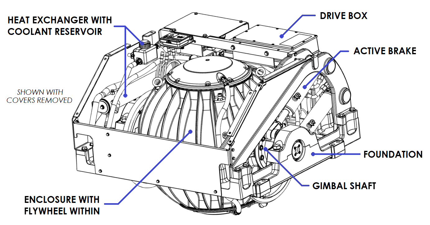
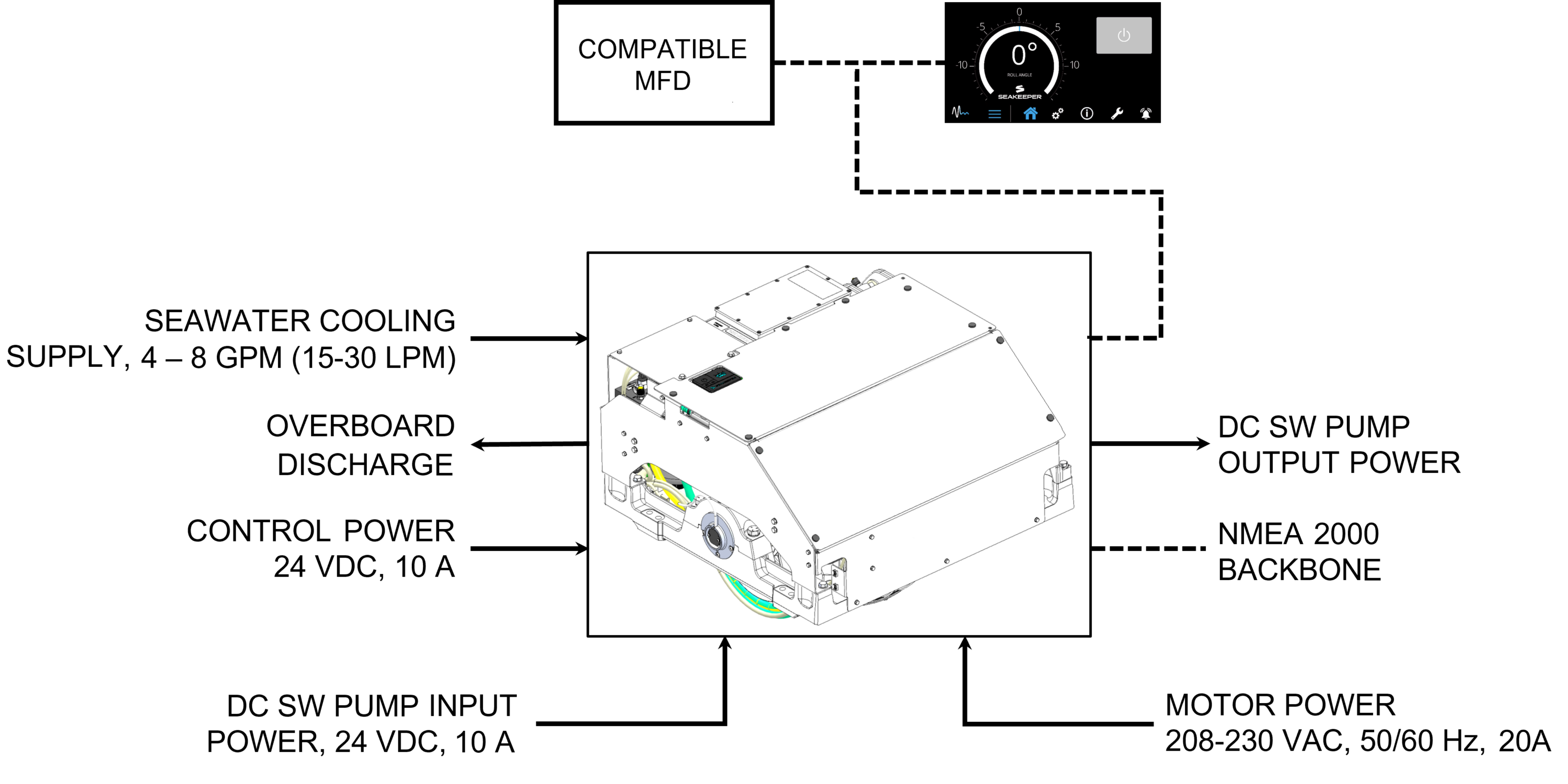
A Seakeeper 9 consists of a Gyro assembly, a CAN communications cable, and a Display. Figure 1 illustrates the interconnection of these components and their interface with the boat.
Seakeeper 9 technical specifications provided in Section: Specifications and Summary, list the power consumption, total weight, and dimensions of the major components. Gyroscopic principals that apply to boat roll control are discussed on Seakeeper’s website at www.seakeeper.com. The Seakeeper website also contains videos of Seakeeper operation and a variety of different boats operating in waves with the Seakeeper on and off. It is recommended that the reader play these videos prior to reading the remainder of this manual.
The gimbal angle and the rate of rotation about the gimbal axis (termed precession rate) play an important role in its operation. These parameters are illustrated in Figure 2. At zero degree gimbal angle, the sphere is vertical; it can precess a maximum of +/- 70 degrees about this position. The amount of torque that the Seakeeper exerts on a boat’s hull to counter the wave induced roll is directly proportional to the precession rate. The farther the Seakeeper is from vertical (zero degrees) the lower the anti-roll torque. The vertical arrows in Figure 2 illustrate the direction of the forces that the Seakeeper exerts on the boat’s hull to damp roll motion.
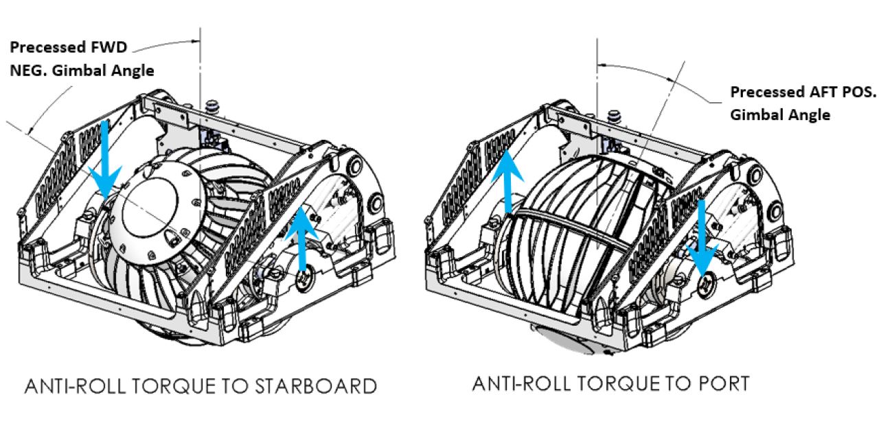
Seakeeper precession is actively controlled by an electronic controller and a hydraulic brake throughout each roll cycle so the Seakeeper supplies the maximum anti-roll torque and does not make mechanical contact with the hard stops that limit the maximum gimbal angle travel to +/- 70 degrees.
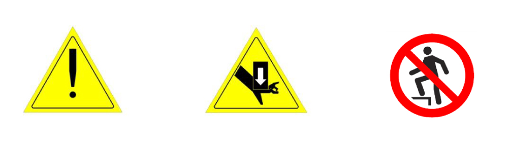
There is a large torque about the gimbal axis when the Seakeeper is precessing. Seakeeper cover panels are provided to prevent personnel or equipment from contacting the Seakeeper while it is in operation. These covers should not be stood on or have anything placed on top. The covers should always be in place during operation.
___________________________________________________________________________________________
If it is ever necessary to touch the Seakeeper while the flywheel is spinning, the Seakeeper must be locked at the display to stop the Seakeeper from precessing.
___________________________________________________________________________________________
Seakeeper maintenance should not be attempted unless the Seakeeper is locked, the flywheel has stopped spinning, and AC input power disconnected for at least 10 minutes due to remote start capabilities in some installations.
2.2 Seakeeper Assembly
The Seakeeper assembly consists of a flywheel housed in a cast aluminum vacuum-tight enclosure. The flywheel spins about a vertical axis and is supported by upper and lower pairs of bearings. A DC brushless motor mounted inside the enclosure spins the flywheel at high speed.
The enclosure is fastened to two gimbal shafts that are supported by gimbal bearings on either side. These shafts establish an athwartship gimbal axis about which the flywheel and enclosure precess or rotate up to +/- 70 degrees during operation. The gimbal bearings are supported by a foundation which is attached to the hull structure. This foundation transfers the loads that the Seakeeper produces to the hull structure.
An active hydraulic brake mechanism is located on the Seakeeper assembly to regulate the Seakeeper’s precession motions about the gimbal shaft. It includes two hydraulic cylinders and a hydraulic manifold.
A coolant pump, heat exchanger, and reservoir are located near the manifold. A glycol/water mix is circulated through a closed loop to the motor drive box, hydraulic manifold, and the end caps of the enclosure to remove heat.