Seakeeper 5 / 6 Installation Manual (90402-4) 6/5-222-5365 to 6/5-233-5846
3.4 Electrical Equipment Mounting
Precautions: Each item of electrical equipment has specific mounting instructions. These instructions
should be followed to ensure proper function of the Seakeeper.
Do NOT move Seakeeper mounted components from their
locations or incorrect Seakeeper operation will result.
3.4.1 Seakeeper 6 Display Options
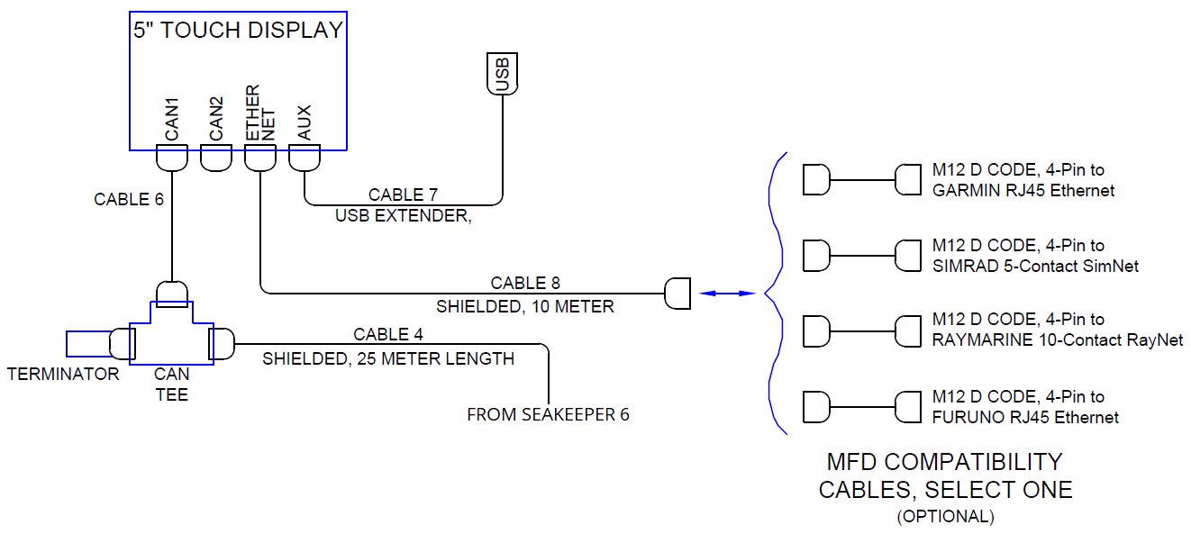
The Seakeeper 6 includes a 5″ Touch Screen Display (P/N 30296) standard. The 5″ Touch Display can be integrated with compatible Multifunction Display systems, per the MFD Compatibility Technical Bulletins.
The Seakeeper MFD App provides an interface for controlling the Seakeeper 6 and viewing the Settings, Service, Info, and Alarm pages from a compatible MFD.
The following figures provide schematics of display options. The subsequent sections outline the instructions and references for connecting the Seakeeper 6 to MFD display option.
3.4.2 Connecting to an Optional Compatible MFD
- The Seakeeper 6 can be connected to a variety of available MFD systems. Refer to the Technical Bulletins Section of the Seakeeper Technical Library for manufacturer specific MFD compatibility technical bulletins.
- MFD specific Technical Bulletins will be updated regularly as new MFD systems become compatible. Currently GARMIN, RAYMARINE, NAVICO (Simrad, Lowrance, B&G), and FURUNO offer compatible MFD models.
- Once a compatible MFD has been selected, refer to the appropriate manufacturer specific Technical Bulletin for integration instructions.
- Connect Seakeeper-supplied Cable 9 (P/N 30330), D-Code 10 m cable to MFD manufacturer-specific Ethernet adapter cable. Custom Ethernet cables for specific MFD manufacturers are available through Seakeeper and must be purchased with the Seakeeper 6 if connecting to an MFD.
3.4.3 Installing the Seakeeper 5″ Touch Display
- Touch Display Mounting Instructions, Surface Mount
- Console space required: Approx. 5.24 W x 3.70 H in. (133 x 94 mm)
- Mounting Instructions, Surface Mount: See Drawing No. 90438 – 5″ Operator Display Envelope and Mounting Details, for details.
- CAN Communications Tee Adapter and Terminator Mounting Instructions:
The CAN Cable Assembly (P/N 30332, Cable 4) is an 82 ft (25 m) shielded cable and the largest connector is a molded plug with maximum outer diameter of .58 in. (14.8 mm)
- Console space required, Rear: Approx. 4 W x 3 H in. (102 x 76 mm)
- Mounting Instructions: Rear mount on vessel console panel, within 1 ft (0.3 m) of Display.
- Hardware required: One mounting screw for .197 in. (5 mm) diameter mounting hole on Tee Adapter.
- USB Extension Cable Assembly Mounting Instructions:
Cable 7 is 6.5 ft (2 m) long cable
- Console space required: Approx. 2 W x 2 H in. (51 x 51 mm), within 5 ft (1.5 m) from Touch Display.
- Mounting Instructions, Surface Mount: Use panel cutout as shown in Section: Display Installation Template. Maximum panel thickness 1/8 in. (3.2 mm).
- Install sealed USB connector end of the extender cable assembly in panel from rear and secure with hex jam nut (provided) on front.
- Connect M12 connector end of the extender cable assembly to the rear of the Touch Display on receptacle AUX.