Seakeeper 40 Installation Manual (90715-2) 40-234-0043 - 40-244-0120
2.5.1 Preparation of Vessel Structure
Refer to Seakeeper Drawing No. 90878 – Seakeeper 40 Bond-In Installation Details. Important dimensional and load information is given in this drawing that will impact the design details of the structure that will receive the Seakeeper as well as selection of the adhesive to bond the Seakeeper into the hull. Reference TB-90382 – Structural Adhesive Recommendation for the recommended adhesives for bond-in installation.
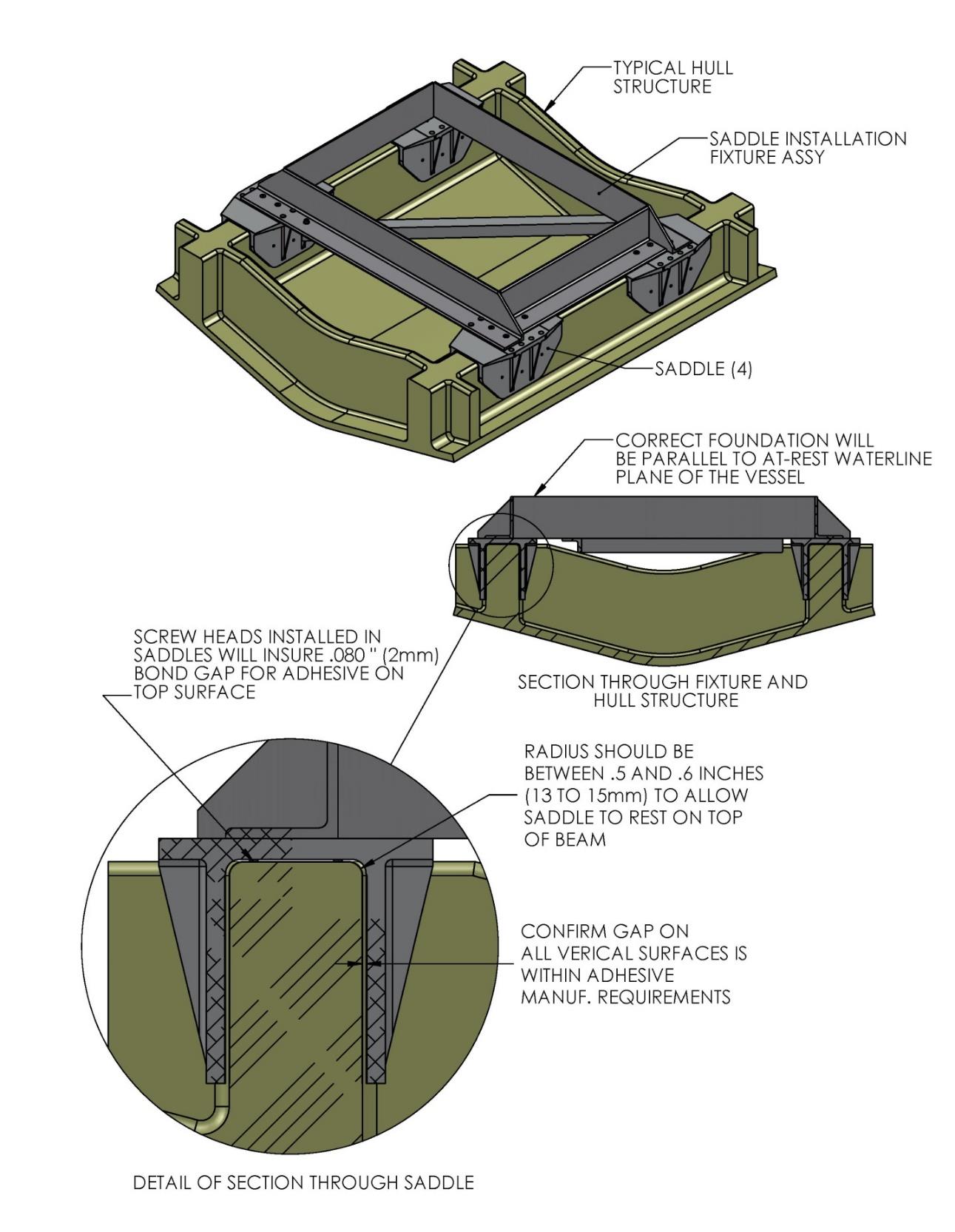
The foundation “saddles” of the Seakeeper are designed to be bonded directly to the composite hull structure of the vessel to effectively distribute Seakeeper loads. A complete bond is required between the inside surface of the saddles and the hull structure. An estimate of adhesive volume required should be calculated for each installation based on gaps between saddles and structural members. There is some adhesive waste as a part of the process so a good rule of thumb is to purchase 50% more adhesive than estimated volume to ensure a complete bond. Depending on conditions and adhesive used, two workers may be required to apply the adhesive at the same time to finish the installation before the adhesive starts to cure. To aid in determining the quantity of adhesive required, the interior surface area (bonding surfaces) of each saddle is 325 in.2 (2,097 cm2) for a total bonded surface area for all four saddles of 1,300 in.2 (8,387 cm2).
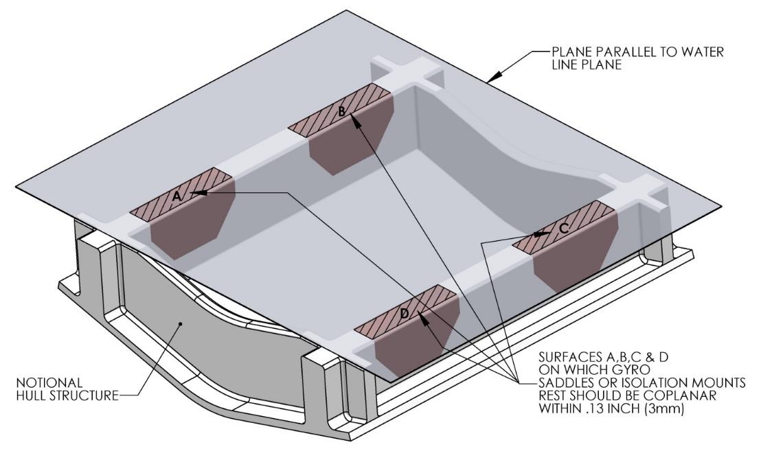
The hull structure supporting the Seakeeper should be arranged so the Seakeeper is parallel to the waterline. In addition, the four areas on top of the beams that the saddles will bond to need to be co-planar within 0.13 in. (3 mm) to minimize potential distortion of Seakeeper support frame when installed, as shown in Figure 13.
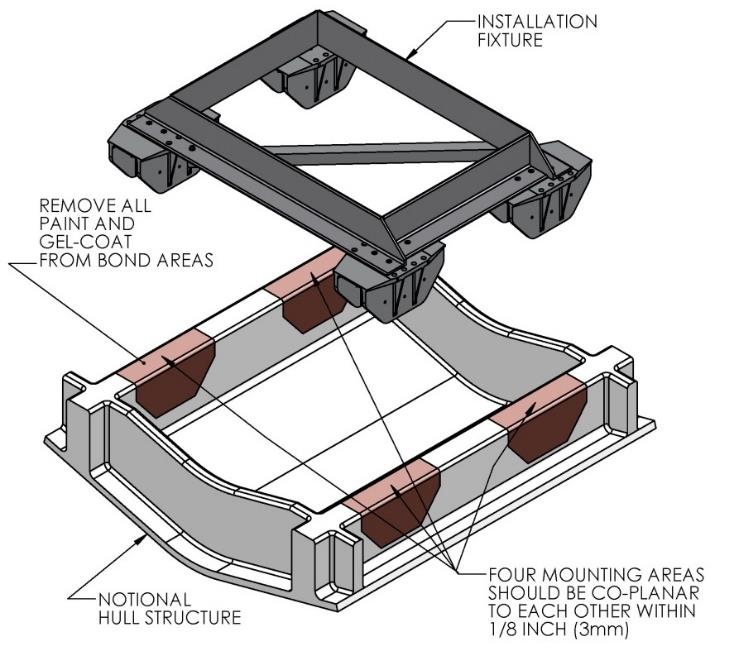
Note that any paint or gel-coat present in bond area should be removed so that adhesive will bond directly to laminate fibers and resin.
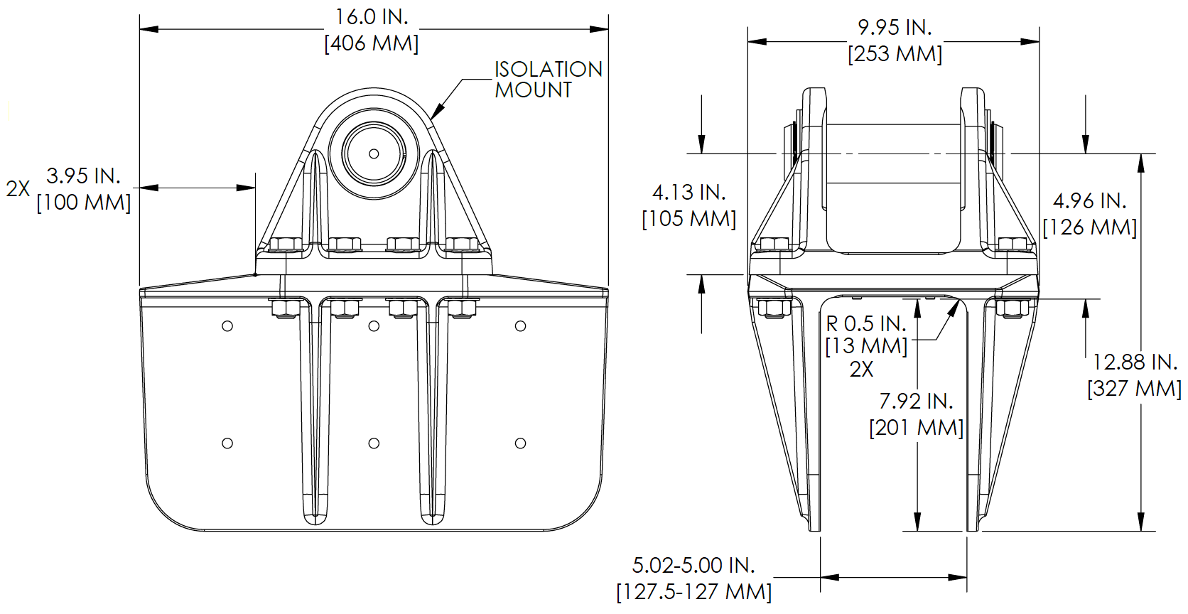
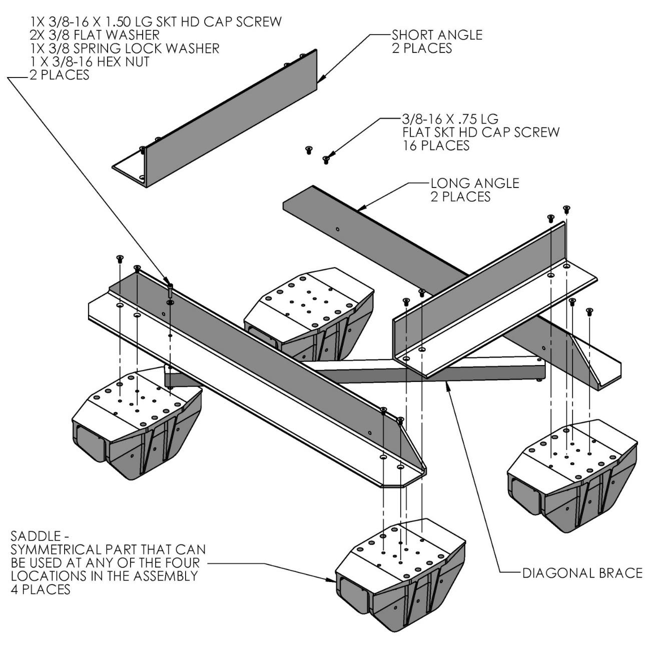
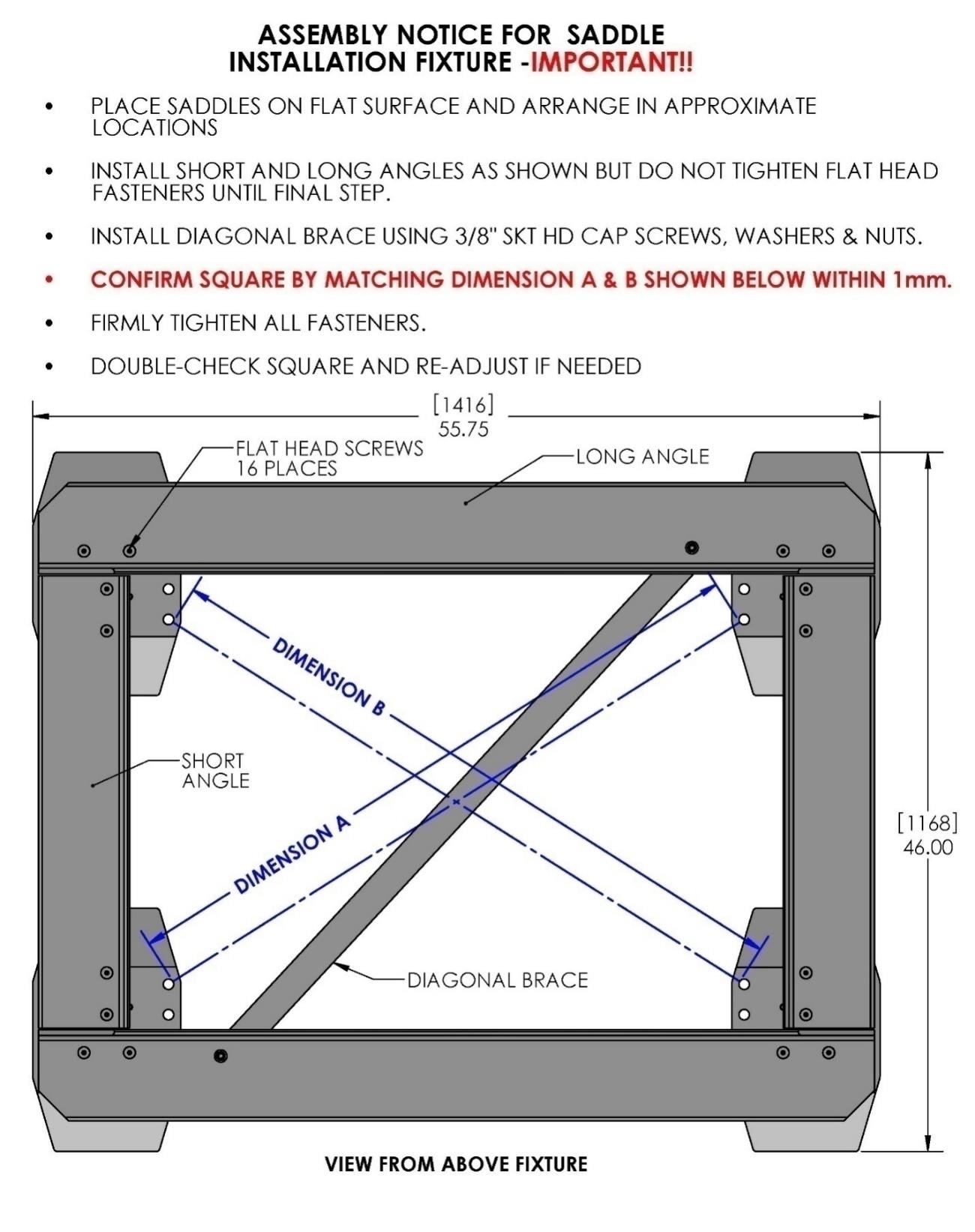
Seakeeper provides an installation fixture template (P/N 90088), that locates the saddles at the proper spacing both in the forward-aft direction and the port-starboard direction. See Figures 8, 9, and 10 below. Once assembled with the provided saddle fittings, the fixture can be used to check clearances and alignment of the hull structure. The fixture will allow the builder / installer to lay-up and adjust the foundation dimensions to create a low-clearance fit between the Seakeeper foundation saddles and the hull structure. Shear strength of the adhesive will be maximized if the cured thickness between the vessel structure and the Seakeeper saddles is at the thinner end of the adhesive manufacturer’s recommended range. Therefore, the fixture should be used to confirm that the overall dimensions of the foundations are square and level and that the adhesive gap is within Seakeeper’s recommended range of 0.04 in. to 0.13 in. (1 to 3 mm).
Note: Do NOT use the installation fixture to establish Seakeeper envelope dimensions. Refer to Drawing No. 90878 – Seakeeper 40 Bond-In Installation Details, for envelope dimensions. A 3-D model of the Seakeeper is available on the Seakeeper website (www.seakeeper.com) to aid in designing the Seakeeper foundation and the space around the Seakeeper.
Hull Preparation
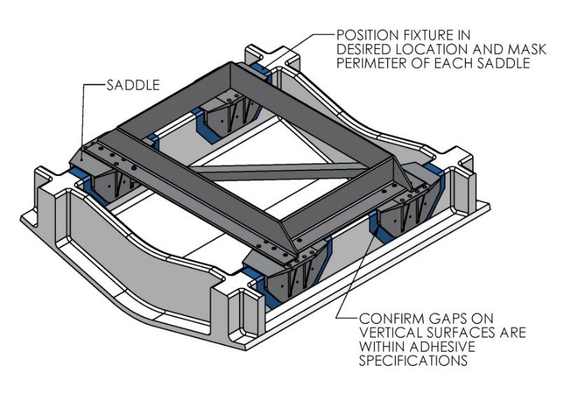
- Position installation fixture (Figure 11) on hull girders noting recommended clearances for maintenance from Drawing No. 90878 – Seakeeper 40 Bond-In Installation Details. Check that the screws fastening the saddles to the installation fixture are tight (Figure 9).
- Mask hull area (as shown in blue, Figure 12) around foundation saddles for easy clean-up and to create an outline of surface area to receive adhesive, as shown in brown (Figure 13). Ensure that the bond gap is within adhesive manufacturer’s recommended thickness, or 3 mm if using Plexus MA590.
- Raise fixture clear of foundation. Check all four mounting areas are co-planar to within 0.13 in. (3 mm) to each other, as well as parallel to the water line plane, as shown in Figure 13.
- Thoroughly clean with alcohol or acetone all areas (highlighted in brown, Figure 13) of girders to be bonded to remove any contaminates. Use new paper towels for cleaning, not shop rags.
- Remove any paint or gel-coat from bond surfaces so that adhesive will bond directly to laminate fibers and resin.
- Thoroughly sand girder bond surfaces with 80 grit sandpaper. (IMPORTANT – BOND STRENGTH MAY BE REDUCED IF THIS STEP IS SKIPPED.)
- Wipe surfaces clean from dust with alcohol or acetone using new paper towels, not shop rags.
- Re-position installation fixture on girders and double-check that the adhesive gap is within the adhesive manufacturer’s maximum recommended thickness. Seakeeper recommends a maximum gap of 3 mm if using Plexus MA590.
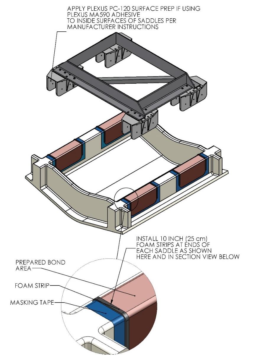
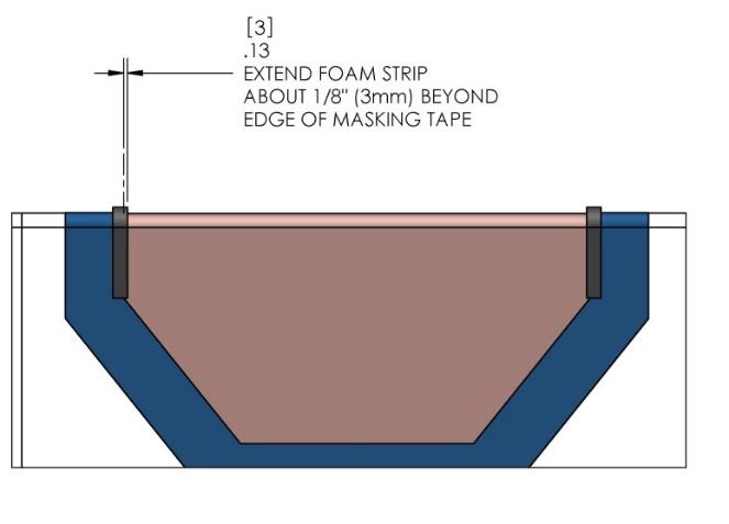
- Lift installation fixture clear of foundation. Apply Seakeeper provided adhesive backed foam strips at the eight locations shown (each end of four saddles) in Figure 14 below. These strips are to serve as a dam to minimize adhesive escaping out the ends of the saddles as they are positioned over the bond area.
Note: If bonding saddles to a metal structure, contact Seakeeper for hull preparation instructions.