Seakeeper 40 Installation Manual (90715-2) 40-234-0043 - 40-244-0120
4.3 Connecting Seawater to Heat Exchanger
Connecting Seawater Pump to Heat Exchanger
- Connect seawater from installer-supplied pump to lower 1 in. (25.4 mm) hose barb on heat exchanger. Use the same practices as other below waterline seawater plumbing. Required flow rate is 13 GPM (49 LPM) minimum and 15 GPM (57 LPM) maximum.
- Connect seawater discharge (upper hose barb) to overboard drain. Use the same practices as typical below waterline seawater plumbing.
- In addition to initial operation at dock, new installations should be checked with a flow meter for minimum 13 GPM (49 LPM) and maximum of 15 GPM (57 LPM) flow under all normal operating conditions.
- If no other method of confirming flow is available, discharge line may be temporarily diverted to a bucket. Flow is calculated from time to fill a known volume.
- A self-priming seawater pump (customer/installer supplied) may be required due to installation location to maintain water flow in all underway conditions where cavitation near the intake may occur and potentially cause an air-lock condition restricting seawater flow to the heat exchanger.
- Inspect raw water plumbing after sea trial for any signs of leakage.
- Heat exchanger contains removable end-caps to provide access for cleaning the tube bundle.

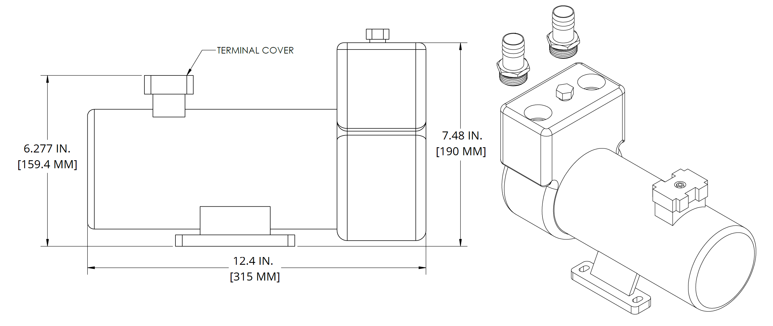
Seakeeper Optional DC Seawater Pump (P/N 30529)
- Seakeeper offers a self-priming DC Seawater Pump as an optional addition, P/N 30529 – 24 VDC Seawater Pump, shown in Figure 29.
- Pump fittings are 3/4 in. NPT. To connect to Seakeeper 40 heat exchanger, a 3/4 to 1 in. barbed adapter will be necessary. DO NOT use bronze or brass fittings on the optional DC Seawater Pump. Use pipe sealant on the threads and other connections.
- The base does not require direct mounting if one of the pipe flanges is rigid mounted. Do not rigid mount both the flanges and the base to avoid mounting tolerances that may distort the motor base. Install the pump with the shaft in a horizontal direction. NEVER install the pump vertical with the motor below the pump.
- Figure 29 provides a mounting hole dimensions for mounting the DC Seawater Pump.
- The pump assembly is pre-wired for connection to the Seakeeper 40 wire harness through Cable 5. The pump specifications are as follows:
| Voltage | 24 VDC |
| Overcurrent Protection Rating | 20 A |
| Suction Lift | 26 FT |
| Flow Rate | 23 GPM with 10 FT suction head |
| Ignition Protection | ISO 8846 or equivalent |