Seakeeper 4 / 4.5 Installation Manual (90762-1)
3.2.1 Seakeeper 4 Motor Power Connection

Reversing polarity on the DC power input to the Seakeeper can result in damage to electronics in the control system.
High Current 12 VDC Power Source Requirements
- One 12 VDC, 100 A (Customer supplied) for Seakeeper flywheel motor power.
- A dedicated breaker should be used for each Seakeeper in a multiple Seakeeper installation.
High Current 12 VDC Power Connection
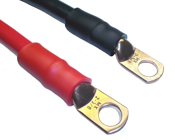
- Connect high-current power red and black cables, 2 AWG conductors, to the 12 VDC power source.
- Both cables (red and black) are supplied at length 13 ft (4 m) and approximately 0.5 m is routed within the gyro frame.
- If installing cables NOT provided by Seakeeper, ensure the following:
- Cable lengths do not exceed 29.5 ft (9 m)
- Cable gauge is 2 AWG or larger
- Cables bound together but not coiled
- Connect high-current power positive (B+, red) conductor through 100 A overcurrent protection device, dedicated battery isolation switch (customer supplied), and to battery positive (B+) terminal.
- Connect high-current power negative (B-, black) conductor directly to battery negative (B-) terminal or to vessel main negative bus.
- If the 2 AWG high current 12 V power input conductors are shortened or lengthened, use heavy-duty eyelet (closed end) terminal such as Molex 19221-0235 and follow instructions outlined in the following steps.
- The bare wire strands should extend fully into the barrel of the heavy-duty eyelet and be crimped in two places if possible then sealed with double-wall heat shrink tubing. Crimp heavy-duty terminals with Quick Cable 4245 Crimp Tool, Molex19284-0034 Crimp Tool, or equivalent using manufacturer’s instructions.
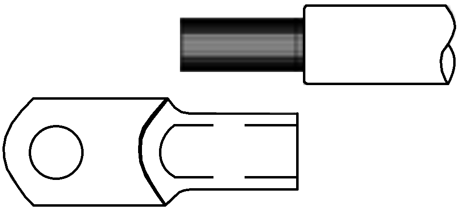
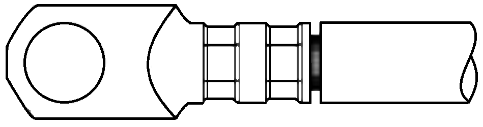
- Use heavy-duty eyelet (closed end) terminal such as Molex 19221 – Strip insulation from 2AWG conductor to the length of the terminal barrel approximately as shown.
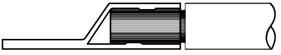
- Insert stripped end of 2 AWG conductor fully into barrel of heavy-duty eyelet (closed end) terminal, approximately as shown.
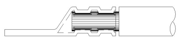
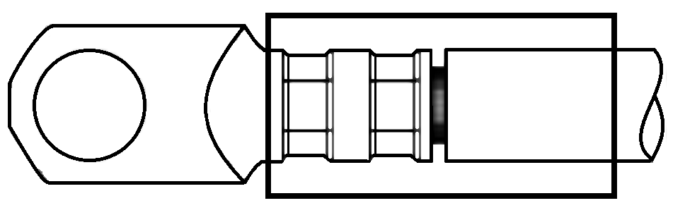
4. Crimp with quick cable 4245 cub crimp tool or equivalent, double
crimp, as shown.
- The resultant crimp(s) should fully enclose and confine the conductor strands from all sides and withstand an aggressive manual pull test.
- Install approximately 1.5 in. (38 mm) of double wall (adhesive lined) heat shrink tubing over both the terminal barrel and the conductor insulation. Heat shrink in place until tubing conforms to barrel and conductor shape and adhesive seals the junction (See figure below).