Troubleshooting Guide
Seakeeper Ride | Troubleshooting Guide
Troubleshooting Introduction | Tables
Updated 9/22/2025
1/2
This troubleshooting guide contains descriptions of issues that may be encountered while using or setting up the Seakeeper Ride system and how to resolve these issues. Please become familiar with all associated documentation before attempting to resolve issues encountered.
Associated Documentation
User Interface Questions/General – Seakeeper Ride Operation Manual
Configuration Issues – Seakeeper Ride Configuration Instructions
Maintenance – Seakeeper Ride Maintenance
Mechanical Issues – Seakeeper Ride Mechanical Installation Guide
Electrical Issues – Seakeeper Ride Electrical Installation Guide
Drawing 90609 (2 Controller Systems) – 3.1 Drawings (Dual) – Seakeeper Manuals
Drawing 90654 (4 Controller Systems) – 3.2 Drawings (Quad) – Seakeeper Manuals
Tables

ATTENTION: For all troubleshooting issues ensure the following:
- The Software Module is updated to the most current version of software.
- The MFD is updated to the most current version of software.
- There is a stable GPS connection.
- Some Service Menu items are protected by a code to prevent accidental adjustment of critical settings. Refer to Service Menu Items – Seakeeper Manuals for the code to access these items.
- Avoid performing a factory reset unless specifically instructed in the troubleshooting steps associated with the issue and only after following all other steps.
- Note that the Fault History within the Menu (accessed by the three lines icon) shows codes that have appeared in the past, NOT codes that are active. DO NOT clear the Fault History.
- If after following the troubleshooting instructions contained in this manual, the issue is still not resolved, reach out to Seakeeper for additional assistance.
| Common Fault Codes | |||
|---|---|---|---|
| Issue | Likely Reason(s) | Solution | Additional Details |
| 555 – LossGPSFix | No GPS connection, because: Boat is indoors. Blocked antenna signal. GPS antenna is defective or broken. Main unit is mirrored to another unit causing GPS or NMEA2000 issues. | Move boat outside where GPS can get a good signal. Repair or adjust GPS antenna. | Fault 555 & 554 – GPS & NMEA – Seakeeper Manuals |
| 554 – NMEA2000Fault | No GPS connection, because: Cable between Software Module and NMEA 2000 network is loose or damaged. Boat’s NMEA 2000 network is not correctly assembled. Main unit is mirrored to another unit causing GPS or NMEA2000 issues. | Check cable between Software Module and NMEA 2000 network. Replace if needed. Restore power to the boat’s NMEA 2000 network. Install terminators on the ends of the boat’s NMEA 2000 network. Verify Ride is visible on NMEA 2000 network. | Fault 555 & 554 – GPS & NMEA – Seakeeper Manuals |
| 256 – Port1AgeCount 257 – Port2AgeCount 259 – Starboard1AgeCount 260 – Starboard2AgeCount 262 – Pitch1AgeCount 263 – Pitch2AgeCount | Configuration incomplete. Connection between Software Module and Distribution Module loose or damaged. Actuator Cable connection to Distribution Module loose or damaged. Power Cable connection to Distribution Module loose or damaged. Electromagnetic interference present. | See ‘No Controllers Found’ message. Electromagnetic Interference: If codes consistently occur when turning on and off another electrical device such as a jack plate or windlass, ensure the Seakeeper Ride wires are not run/bundled with the wires of the other electrical device. | |
| 556 – Port1NoCANFault 557 – Starboard1NoCANFault 558 – Port2NoCANFault 559 – Starboard2NoCANFault | Connection between Software Module and Distribution Module loose or damaged. | Software Module has lost power while Distribution Module remained powered. See ‘No Controllers Found’ message. | |
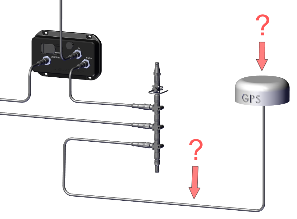
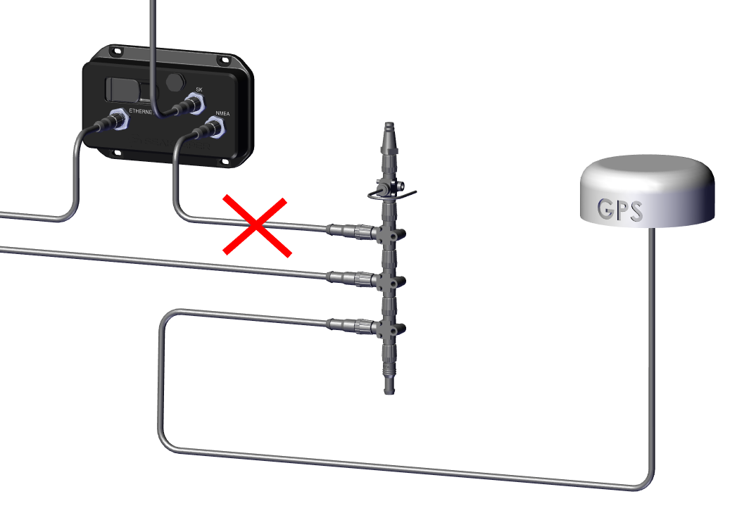
| 1024 – No CAN Communication | Ride Proprietary CAN Bus Signal is interrupted in delivering data from the Software Module to the Controllers. Boat’s NMEA network may be connected to the Ride network, a faulty cable or tee may be present, etc. | Ensure there is no cross between the Ride Proprietary CAN Bus Network and the boat’s other NMEA and communication networks. Pay particular attention to GPS, Optimus, Yamaha, or other systems that may be connected the Ride network. Refer to the Electrical Installation Manual, checking that the Ride network is setup as shown in blue in Figure 1 and as shown in Figure 12. Rebuild the Ride network using new cables and tees. | |
| 1040 – UI Issue | Some/all Ride Proprietary CAN Bus devices are not detected, or boat’s other network devices are connected to the Ride network. | See 1024 – No CAN Communication. | |
| Other Fault Codes | ||
|---|---|---|
| Issue | Likely Reason(s) | Solution |
| 265 – Port1RangeFault 266 – Port2RangeFault 268 – Starboard1RangeFault 269 – Starboard2RangeFault 271 – Pitch1RangeFault 272 – Pitch2RangeFault | Ride Controller Blade position was different than expected. | Check that the Blade is firmly attached and not broken. Redo Controller Zeroing. |
| 283 – Port1NotResponsive 284 – Port2NotResponsive 286 – Starboard1NotResponsive 287-Starboard2NotResponsive | Blockage to Blade deployment. | Ensure no contamination is binding between Blade and Seal Plate. Ensure no contamination is preventing Actuator movement. Check Blade zero position. Check Blade Diagnostics to verify correct direction of movement. |
| 508 – TrimAngleOutOfRange 509 – ListAngleOutOfRange 510 – RollRateOutOfRange 511 – YawRateOutOfRange 512 – PitchRateOutOfRange 518 – LongAccelOutofRangeFault 519 – LatAccelOutofRangeFault 520 – VertAccelOutofRangeFault 521 – RateLimit | GPS signal is inconsistent. The Software Module is mounted at an angle greater than 15˚. Software Module is mounted upside down. Angle Calibration is off. | See 555 – NMEA2000Fault. Remount the Software Module upright at an angle less than 15˚ both front to back and side to side. Redo the Attitude Calibration. 2.6. Service – Seakeeper Manuals |
| 513 – ICMTempOutOfRange 514 – ADXLTempOutOfRange 515 – CPUTempOutOfRange | Heat source near Software Module. | Shut off power to all systems. Ensure there are no signs of fire and remove any sources of heat from near the Software Module. |
| 516 – VBattLowFault 517 – VBattHighFault | Battery under 9.5 V or over 16 V for more than 2 seconds. | Shut off power to all systems. Check voltage at batteries. If battery voltage is good, inspect terminals and wiring. Remove corrosion, replace power cable, or increase wire gauge if needed. For low voltage: -Recharge battery if needed. -Replace battery if needed. -Inspect alternator. For high voltage: -Consult with manufacturer to inspect batteries or alternator. |
| 522 – IMU Orientation Startup | Software Module is installed incorrectly. | Review mounting of Software Module and ensure it meets specification of installation manual. 6.1 Software Module – Seakeeper Manuals |
| 523 – IMUOrientation | Software Module orientation selection (Bow or Stern) does not match physical orientation. | Ensure physical orentation of the Software Module matches selection within the Ride app. The orientation can be found under Settings -> Service -> System Status. |
| 553 – EPEFault | GPS accuracy low. | Ensure proper mounting of GPS antenna and clear line of sight to the sky. Select alternate GPS source or replace faulty GPS source. |
| 556 – Port1NoCANFault 557 – Starboard1NoCANFault 558 – Port2NoCANFault 559 – Starboard2NoCANFault | Connection between Software Module and Distribution Module loose or damaged. Software Module has lost power while Distribution Module remained powered. | See ‘No Controllers Found’ message. |
| 570 – ConfigurationFault 571 – Port1ConfigInProgressFault 572 – Port2ConfigInProgressFault 573 – Starboard1ConfigInProgressFault 574 – Starboard2ConfigInProgressFault 575 – Pitch1ConfigInProgressFault 576 – Pitch2ConfigInProgressFault | Configuration incomplete. | Factory Reset and repeat the configuration process. Ensure the software is up to date. Vessel Attitude Control System | Motion Control Software Updates |
| 582 – SystemUpdateFailed | Software Update does not load properly to the Software Module. | Is the software already updated? Review details of software update instructions to ensure memory stick formatting and handling procedure is correct. Vessel Attitude Control System | Motion Control Software Updates |
| 1025 – GyroIncompatible | The detected Seakeeper Gyro system is not compatible with this version of Ride. | Please update your Gyro software to the latest version. |
| 1041 – CANUpdateSoftwareNotFound 1044 -CANUpdateFailedToProgram 1043 – CANUpdateFailedToDisableSystem 1042 – CANUpdateDowngradeNotAllowed | Unable to find software for some/all connected CAN devices. Software updates of some/all CAN devices failed. Failed to disable the system so we cannot update CAN device software. CAN software downgrades are not supported and a device with a newer version than expected was detected. | Insert LATEST software into micro USB of software module and cycle power to full system (Distribution Module and Software Module). Check the Seakeeper CAN Bus backbone for proper terminator resistors. |
| 1050- “Unable to authenticate Ride system as some/all CAN devices are not detected.” 1051- “Failed to authenticate Ride system.” 1052- “Authentication Fault” | The actuator could be disabled if there is not a genuine software module. The actuator and software module being used are not compatible. | Ensure the correct sized actuator/controller type for the system is installed. (Ex. If the actuators being used are for a 450 system, the software module must also be a 450 system software module.) |
| 2050 – FailedToRebootController | Invalid action such as attempting recalibration of Blade zero point with active AgeCount fault. | Clear all faults before performing Service menu items. |
| Ride : Full Code (Garmin) | Fault is present in the Seakeeper Ride app. | Navigate to the Seakeeper Ride app and address the fault present. |
| Configuring and Testing the System | ||
|---|---|---|
| Issue | Likely Reason(s) | Solution |
| Stuck in Init – During configuration, ‘Please Connect both Controllers’ shows on screen and will not continue, but Controller cables are inserted. | No power to Distribution Module. No NMEA or bad NMEA connection to Distribution Module. Incorrect Controller pinout. | Check 15 or 25 amp circuit breaker or fuse. Check battery switches and terminal connections and verify polarity is not reversed. Ensure that Distribution Module power cable is recieving consistent 12 V power and is fully inserted (clicks into place). Verify that Seakeeper Ride Proprietary CAN Bus is setup correctly. See 8.1 Seakeeper Ride Proprietary CAN Bus – Seakeeper Manuals. Replace NMEA cable if necessary. Ensure there is a tee with a resistor installed next to the Distribution Module. This should receive the cable that runs from the Seakeeper Ride Proprietary CAN Bus and have a drop cable that connects to the Distribution Module. Ensure there is no cross between the Ride Proprietary CAN Bus Network and the boat’s other NMEA and communication networks. Pay particular attention to GPS, Optimus, Yamaha, or other systems that may be connected the Ride network. Verify pinout matches diagram in 8.3 Distribution Module Wiring – Seakeeper Manuals. Trace the Distribution Module power cable and power tee and make sure they are connected to a common positive and negative 12 V source. |
| Controller Blades are opposite (left arrow moves Port Controller or vice versa). | Port and Starboard assignments are flipped. | Factory Reset under Menu, Service, Factory Reset. During re-configuration, pay special attention to Controller Configuration. 2.6. Service – Seakeeper Manuals |
| Controller Blade moves up instead of down OR Port and Starboard Indicators (blue bars) max out around 30%. | Incorrect Cable Orientation assignment. | Factory Reset under Menu, Service, Factory Reset. During re-configuration, pay special attention to Controller Cable Orientation. 2.6. Service – Seakeeper Manuals |
| Controller Blade is not sitting flush with Seal Plate. | Bad Zero Position calibration. | Redo Controller Zero Position. Go to Menu, Service, Controller Zeroing. 2.6. Service – Seakeeper Manuals |
| Screen is blank. | Software Module switches are in the wrong position for the MFD manufacturer. | Follow Configuration Instructions Section 2 – Software Module Switches. |
| ‘Vessel Speed Too High!’ message. | Boat is moving while attempting angle calibration. GPS signal is lost while attempting angle calibration. | Slow down the boat to a stop. Restore GPS signal. See 555 – NMEA2000Fault Issue. |
| Electrical | ||
|---|---|---|
| Issue | Likely Reason(s) | Solution |
| ‘No Controllers Found’ message. | No Seakeeper CAN Bus connection to Distribution Module. Missing Seakeeper CAN Bus Terminator. No power to Distribution Module. Incorrect Controller Cable pinout. | See Section 8 of the Electrical Installation Manual. Ensure the CAN Bus cables are fully inserted, replace if damaged, and verify all wiring matches instructions and diagrams. Ensure Ride CAN Bus network is not connected with any other networks. Check Circuit Breaker. Check that Distribution Module power cable is recieving consistent 12 V power and is fully inserted (clicks into place). Rewire the Actuator Cable Ampseal Plugs if necessary. |
| Seakeeper Ride App not displaying on MFD | Ethernet cable between Software Module and MFD is loose or damaged. No power to the Software Module. Software Module switches are incorrect. MFD issue or software is outdated. | Ensure the ethernet cable is attached. Verify Software Module has power via LED lights inside Software Module rubber cover. 2. Software Module Switches – Seakeeper Manuals. See Section 8.2 of the Electrical Installation Manual and ensure the wiring is correct. See the Powered CAN Bus Tee section in Section 8.1 of the Electrical Installation Manual. Ensure power is flowing to the Powered CAN Bus Tee, the 3 A inline fuse is not blown, and polarity is not reversed. Ensure the Software Module switches are in the correct position for the MFD manufacturer. 2. Software Module Switches – Seakeeper Manuals. Update MFD software. If after ensuring Seakeeper Ride electrical setup is correct, contact the MFD manufacturer to troubleshoot for 3rd party app connectivity. |
| ‘No Connection’ message. | See ‘Seakeeper Ride App not displaying on MFD’ issue. | |
| ‘Searching for OneHelm Device’ | See ‘Seakeeper Ride App not displaying on MFD’ issue. | |
| Keypad is not working or lighting up. | Seakeeper CAN Bus connection to Keypad is loose or damaged. | Ensure the Keypad cable is fully inserted and connected to the Seakeeper Ride Proprietary CAN Bus. Replace if damaged. |
| Position Sensing Fault. | The Blade arms could be loose or the torque arms loose. | Replace the Actuator. |
| Stabilization Issues | ||
|---|---|---|
| Issue | Likely Reason(s) | Solution |
| Boat is listing in Auto Mode. | Attitude Calibration is off. Software Module Orientation is wrong. | Redo the Attitude Calibration under Menu, Service, Attitude Calibration. 2.6. Service – Seakeeper Manuals Redo the Software Module Orientation. 2.6. Service – Seakeeper Manuals |
| Boat is porpoising in Auto Mode. | Software Module Orientation is wrong. | Redo the Software Module Orientation. 2.6. Service – Seakeeper Manuals |
| Boat listing in Manual Mode OR Boat is bow heavy in Manual Mode OR Seakeeper Ride has limited influence above 20 mph. | Bad Zero Position calibration. | Redo the Controller Zeroing and ensure the Blade is perfectly flush with the Seal Plate. 2.6. Service – Seakeeper Manuals |
| Seakeeper Ride appears to do nothing in Auto and Manual modes above 20 mph. | Incorrect Cable Routing Side assignment. Fault or other error is present. | Factory Reset under Menu, Service, Factory Reset. During re-configuration, pay special attention to Controller Cable Orientation. 2.6. Service – Seakeeper Manuals See details on Fault or other error present. |
Troubleshooting | Problems and Solutions
Software Updates.
Seakeeper Ride releases new software approximately every 3 months. Each software update is applicable to all Ride systems. We recommend updating equipment with the latest software prior to starting any troubleshooting. Software updates and instructions can be found here – Vessel Attitude Control System | Motion Control Software Updates. Software updates require a correctly formatted (FAT32) memory card and micro USB adapter. No other files can be present on the memory card for the update to function properly.
The Seakeeper Ride system is not stabilizing the boat.
If the system is in Manual Mode, the Controllers will not move unless they are moved manually by the user. Ensure that the system is in Auto Mode by pressing the button with the Seakeeper Logo in the center of the directional arrows until the word ‘Auto’ is underneath the Seakeeper Logo.
The Seakeeper Ride system is in Auto Mode and is still not stabilizing the boat.
See Diagnostics (2.6. Service – Seakeeper Manuals) in the Service Menu. If the Controllers are not responding as intended while in Manual Mode, they may need to be reconfigured. Please review the entirety of the Seakeeper Ride Configuration Instructions. Make sure that each configuration setting matches the orientation of the Controllers and cable routing.
The directional arrows are not working properly, or user is unsure what they are doing.
A full description of the directional arrows and their function can be found in the Operation Manual (2.1. Home | Auto Mode – Seakeeper Manuals). Note that the Seakeeper Ride controls are not the same as the controls for trim tabs or other transom mounted devices.
The boat moves in the opposite direction of user inputs.
The Controller configuration may be backwards. See Diagnostics in the Service Menu 2.6. Service – Seakeeper Manuals. If the Controllers are not responding correctly while in Manual Mode, they may need to be reconfigured. Perform a Factory Reset from the Service Menu and follow on screen prompts to re-configure the system. Make sure that each configuration setting matches the port and starboard sides the Controllers are on and cable routing.
The boat will not respond in Manual Mode until the directional arrow is pressed multiple times.
Note: Seakeeper Ride only works when boat is moving over 10 mph and power increases with speed so if you’re going slow, it will not be as noticeable.
The zero position of the Actuators may be too high. Visually confirm that the Controller Blade is flush with the Seal Plate when there is no input (the vessel may need to be out of the water to see). If the Controller Blade is not flush with the Seal Plate, the zero position of the Actuator will need to be redone. See the Controller Zeroing portion of the Service Menu (2.6. Service – Seakeeper Manuals).
The boat will not respond at all in Manual Mode.
The cable routing side configuration may be wrong. Perform a Factory Reset from the Service Menu and follow on screen prompts to re-configure the system (2.6. Service – Seakeeper Manuals). Verify that the Actuator Cable orientation matches the configuration under ‘Cable Routing Side’ on the MFD.
The boat occasionally heels to one side or the other.
Be sure to check the maintenance schedule specifically for Actuator Friction.
Use the directional arrows to trim the boat as desired. See 2.1. Home | Auto Mode – Seakeeper Manuals of the Seakeeper Ride Operation Manual.
The boat always heels to one side when there is no input.
- Put the system in Manual Mode by pressing the button with the Seakeeper Logo in the center of the directional arrows until the word ‘Manual’ is underneath the Seakeeper Logo. If the boat heels to one side in Manual Mode with no input, the zero position of the Actuators may be off. Visually confirm that the Controller Blades are flush with the Seal Plates when there is no input (the vessel may need to be out of the water to see). If either Controller Blade is not flush with its Seal Plate, the zero position of the Actuator will need to be redone. Select Controller Zeroing in the Service Menu (2.6. Service – Seakeeper Manuals) and ensure the Blades are perfectly flush with the Seal Plate.
- If the boat rides level in Manual Mode but heels to one side in Auto Mode, check the Software Module orientation by viewing the System Status Screen (2.6. Service – Seakeeper Manuals). Verify that the system orientation matches the direction the Software Module logo is facing.
- If the Software Module Orientation is correct and the boat heels to one side in Auto Mode, the Attitude Calibration will need to be redone. Perform an Attitude Calibration in the Service Menu (2.6. Service – Seakeeper Manuals).
The bow of the boat occasionally rides too high or too low.
Use the directional arrows to trim the boat as desired. See 2.1. Home | Auto Mode – Seakeeper Manuals of the Seakeeper Ride Operation Manual.
The bow of the boat always seems to be pushed down when there is no input.
- Put the system in Manual Mode by pressing the button with the Seakeeper Logo in the center of the directional arrows until the word ‘Manual’ is underneath the Seakeeper Logo. If the boat is bow heavy in Manual Mode with no input, the zero position of the Actuators may be off. Visually confirm that the Controller Blades are flush with the Seal Plates when there is no input (the vessel may need to be out of the water to see). If either Controller Blade is not flush with its Seal Plate, the zero position of the Actuator will need to be redone. Select Controller Zeroing in the Service Menu (2.6. Service – Seakeeper Manuals) and ensure the Blades are perfectly flush with the Seal Plate.
- If the boat rides level in Manual Mode but is bow heavy in Auto Mode, see 3.3. Trim Command Curve (TCC) – Seakeeper Manuals of the Seakeeper Ride Operation Manual and make sure the trim is not set too high at certain speeds. There should generally be little to no trim in the TCC at higher speeds.
- If the TCC is set up correctly and the bow is still heavy in Auto Mode, the Attitude Calibration will likely need to be redone. Perform an Attitude Calibration in the Service Menu (2.6. Service – Seakeeper Manuals).
Note: Be wary of aggressive trim command curve. This can cause unanticipated maneuvering if the boat has not accelerated past the hole shot portion of the curve.
The bow is raising or lowering too much during the mid-speed range.
If the attitude of the bow is irregular or behaving undesirably at certain speeds, please refer to 3.3. Trim Command Curve (TCC) – Seakeeper Manuals of the Seakeeper Ride Operation Manual.
The Seakeeper Ride application is blank on the MFD, the Keypad is not lit, and the Controllers are not moving.
Note: The Seakeeper Ride system may be connected to the boat’s ignition switch, meaning the system will only power on when the key is turned on.
There is power loss either to the Distribution Module or to the Seakeeper Ride CAN Bus Backbone.
Note: In the event there is damage to the terminal ends of any of your Actuator Cable terminals, they can be replaced. Replacement should include all 6 cables in order to keep cable length into the amp seal connector even. Utilize a crimper, part number 58529-1, and genuine amp seal connectors, part number 770678-1. Follow procedure as outlined here.
- Review Drawing No. 90609 – Seakeeper Ride Cable Block Diagram & Arrangement and Section 8 – Wiring and Terminating Cables of the Seakeeper Ride Electrical Installation Manual.
- Verify that the cable to the Distribution Module aft in the boat is connected properly and supplying +12 VDC. Check all power isolation switches and circuit breakers to ensure power is flowing to the Distribution Module.
- Verify that the Powered Tee in the Seakeeper CAN Bus Backbone is connected properly. The red wire must be connected to the ignition switch supplying +12 VDC, and the black wire must be grounded. Check any fuses or switches to ensure power is flowing to the Seakeeper CAN Bus Backbone.
The system has power, but the Seakeeper Ride application is blank on the MFD.
- Open the rubber cover on the upper left-hand side of the Software Module and confirm a green LED is showing to verify the system has power.
- Check the cable between the Software Module and GPS and ensure it is connected properly.
- Update the MFD to the latest software version.
- Confirm the MFD is in the correct application.
- The Seakeeper Ride system may be rebooting or downloading software. Wait for a few minutes and try again.
- See Section 2 – Software Module Switches of the Seakeeper Ride Configuration Instructions and verify that the switches are configured correctly for the MFD brand. See the Seakeeper Ride MFD Compatibility Page to confirm that the MFD is compatible.
The system seems to be functioning and the Keypad lights up, but the Seakeeper application is not loading on the MFD.
The ethernet cable is likely bad. Check the cable connection and replace it if needed. Restart the MFD once connection is fixed.
The system is functioning and the Seakeeper application shows on the MFD, but the Keypad is not lighting up.
Check connection of the Seakeeper cable going to the Keypad. Replace the cable if needed.
The system is stuck in Manual Mode.
Seakeeper Ride requires GPS connection for speed information to operate in Auto Mode. Check that the boat’s GPS has not lost signal. Check the NMEA 2000 cable connection to the Software Module and replace it if needed.
The Controller command indicators are filling in/lighting up correctly, and the Controllers move correctly out of the water, but the Controllers do not seem to have influence on the boat.
The torque arms on the Actuator or the bolts holding the Seal Plate on may not be torqued properly. Check that all the bolts are torqued to the correct values specified in the Seakeeper Ride Mechanical Installation Guide.
Be sure to check the maintenance schedule specifically for Actuator Friction.
Note: If controllers are flashing intermittently during configuration process check to ensure the controllers are assigned to each side, NOT both assigned to 1 side.
- Ensure there are no additional items connected to the Seakeeper CAN Bus network. additional items might collapse the Seakeeper Ride network (notably the NMEA2000 network if connected directly to the Seakeeper Ride network will collapse them both)
Faults
Sensors, faults, and shutdowns are provided to allow unattended operation. Sensors measure Actuator temperatures, Blade deployment, NMEA connectivity, and vessel motion. The Seakeeper Controller sends sensor values and fault information to the MFD and retracts the Blades in the event of a fault condition. The history is recorded in the controller’s memory for subsequent recall if service is needed. Seakeeper and Seakeeper Dealers may access the software to gather run hours, deployment angles and other operation information.
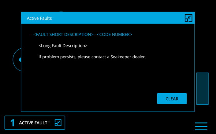
The fault is shown on the MFD with a fault pop up, and on the Keypad (if equipped) with a solid red light. The Seakeeper Application must be used on the MFD to identify and address the fault. Most faults will not clear until the operator presses the fault CLEAR button and the fault condition is no longer present.
A Non-Resposive fault will be accompanied by the Keypad center ring blinking red and blue. This fault is a warning and will allow the system to continue functioning fully.
A view of a typical Fault screen. To reset the fault, press the CLEAR button.
The Fault History page on the Seakeeper Application shows the recent faults and warnings. Faults trigger a pop-up message to be displayed on the Seakeeper Ride application and cause the Keypad to be non-responsive. Warnings will be listed in the fault history but do not affect operation. The history of faults and warnings are in chronological order starting with the most recent. To show the Fault History Page, press the Menu button ![]() , press Faults, and then press Historic.
, press Faults, and then press Historic.
See the Fault Codes table in the previous section for details on a faults that may be seen, likely causes, and solutions.
Fault 555 & 554 – GPS & NMEA
Overview
Seakeeper Ride requires a continuous, reliable GPS signal to function. The faults in this section are Seakeeper Ride communicating that this requirement has not been met, which could have multiple causes.
Fault 555 – LossGPSFix
Fault 555 indicates that Seakeeper Ride detects connection to a valid NMEA 2000 network but does not detect a valid GPS fix (i.e., no good GPS signal is being received).
It may be helpful to verify that the GPS is present and has a fix (good signal) according to the MFD by viewing signal strength in the GPS, Satellite, or Device settings depending on your MFD.
Causes and Solutions:
- Boat is indoors, under a bridge, or too close to other nearby large structures.
- The GPS antenna is blocked by structure or has interference with equipment on the boat. This could be T-tops, bimini tops or other coverings, consoles, other equipment near the GPS, etc.
- GPS antenna is defective or broken.
- NMEA 2000 cable or tee is defective or broken.
- Main MFD unit is mirrored to another unit causing GPS or NMEA 2000 issues.
- Move the boat outdoors or away from potential obstructions.
- Relocate the GPS on the boat for better line of sight to the sky.
- Repair or replace GPS antenna.
- Replace suspect NMEA2000 cable or tee.
- Restructure NMEA 2000 connection between the MFDs. Change or cancel mirroring settings.
Fault 554 – NMEA2000Fault
Fault 554 indicates that Seakeeper Ride detects no connection to the NMEA 2000 network, and consequently, no connection to a valid GPS device.
Causes and Solutions:
- Cable between Software Module and NMEA 2000 network is loose or damaged.
- Boat’s NMEA 2000 network is not correctly assembled.
- Main unit is mirrored to another unit causing GPS or NMEA2000 issues.
- Check cable between Software Module and NMEA 2000 network. Replace if needed.
- Restore power to the boat’s NMEA 2000 network.Install terminators on the ends of the boat’s NMEA2000 network.
- Verify Ride is visible on NMEA 2000 network. Restructure NMEA 2000 connection between the MFDs. Change or cancel mirroring settings.
Simrad NSS4 Connecting to Seakeeper Ride App
The Seakeeper Ride app may not populate automatically on Simrad NSS4 devices if the settings are incorrect. The following instructions describe how to change the ethernet settings to populate the Ride app on the MFD.
Instructions
1. From the home screen of the NSS4, select the SETTINGS gear.
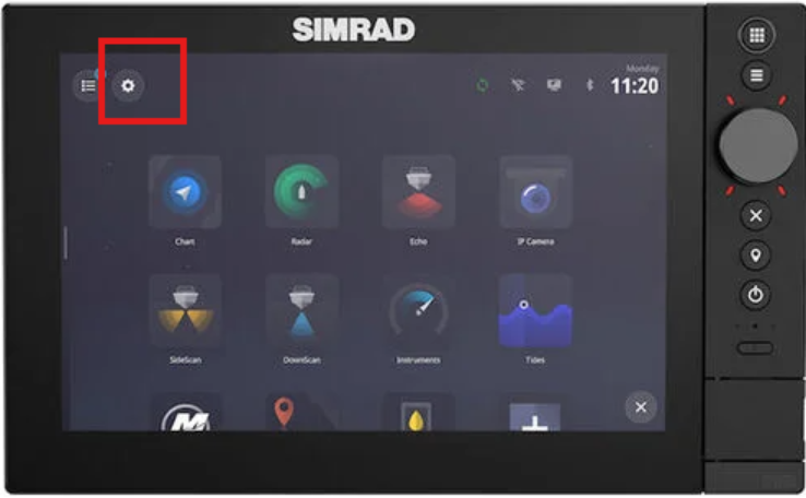
2. Once inside the settings, go to BOAT NETWORK
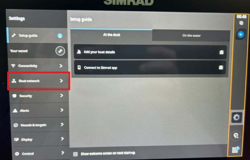
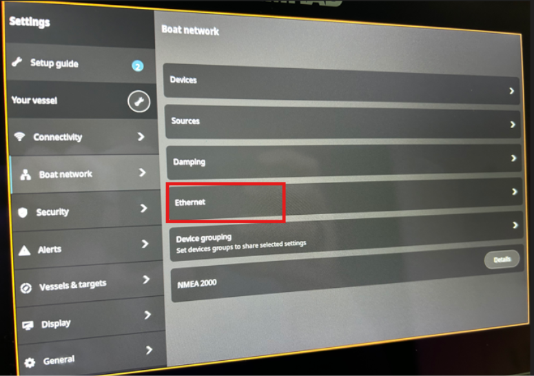
3. From Boat Network, select ETHERNET
4. Next, check the DHCP setting. Switch to AUTO.
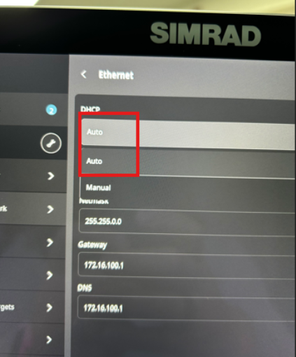
5. Your Ride app should now be successfully appearing on the Simrad NSS4.