Seakeeper 40 Installation Manual (90715-1)
2.3.1 Preparation of Vessel Structure
Seakeeper provided mounting hardware is intended to apply to typical installation arrangements. However, each installation, especially custom aftermarket foundations, should be thoroughly reviewed to ensure the provided hardware meets the required thread engagement for the Seakeeper unit being installed. The mounting bolt thread engagement requirements are outlined in the Installation Manuals and Installation Details Drawings for each Seakeeper model. This also applies to Seakeeper model adapter kits and OEM built frames where the bolt hole depth should be checked to ensure the bolts will not bottom, preventing the bolts from achieving the intended preload.
When the Seakeeper provided hardware is not appropriate, the bolt specification (diameter and thread pitch) and grade should be matched in the required length and used with the Seakeeper provided washers. Mounting bolts should always be torqued to the Seakeeper specification. All Seakeeper provided bolts are metric course thread. Hardware specifications are also listed in the Installation Manuals and Installation Details Drawings.
Refer to Seakeeper Drawing No. 90714 – Seakeeper 40 Bolt-In Installation Details. Important dimensional and load information is given in this drawing that will impact the design details of the structure that will receive the Seakeeper. It is assumed that a proper structural analysis has been performed for the hull structure to which the Seakeeper will be fastened to ensure proper strength margins for the loads the Seakeeper will create during operation.
The hull structure supporting the Seakeeper should be arranged so the Seakeeper is parallel to the waterline in the forward-aft and port-starboard directions (with up to 2° allowance for trim). In addition, the four areas on top of the beams on which the isolation mounts will rest, need to be co-planar within 0.12 in. (3 mm) to minimize potential distortion of Seakeeper support frame when installed.
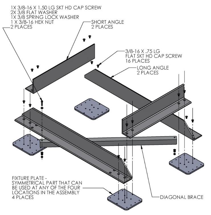
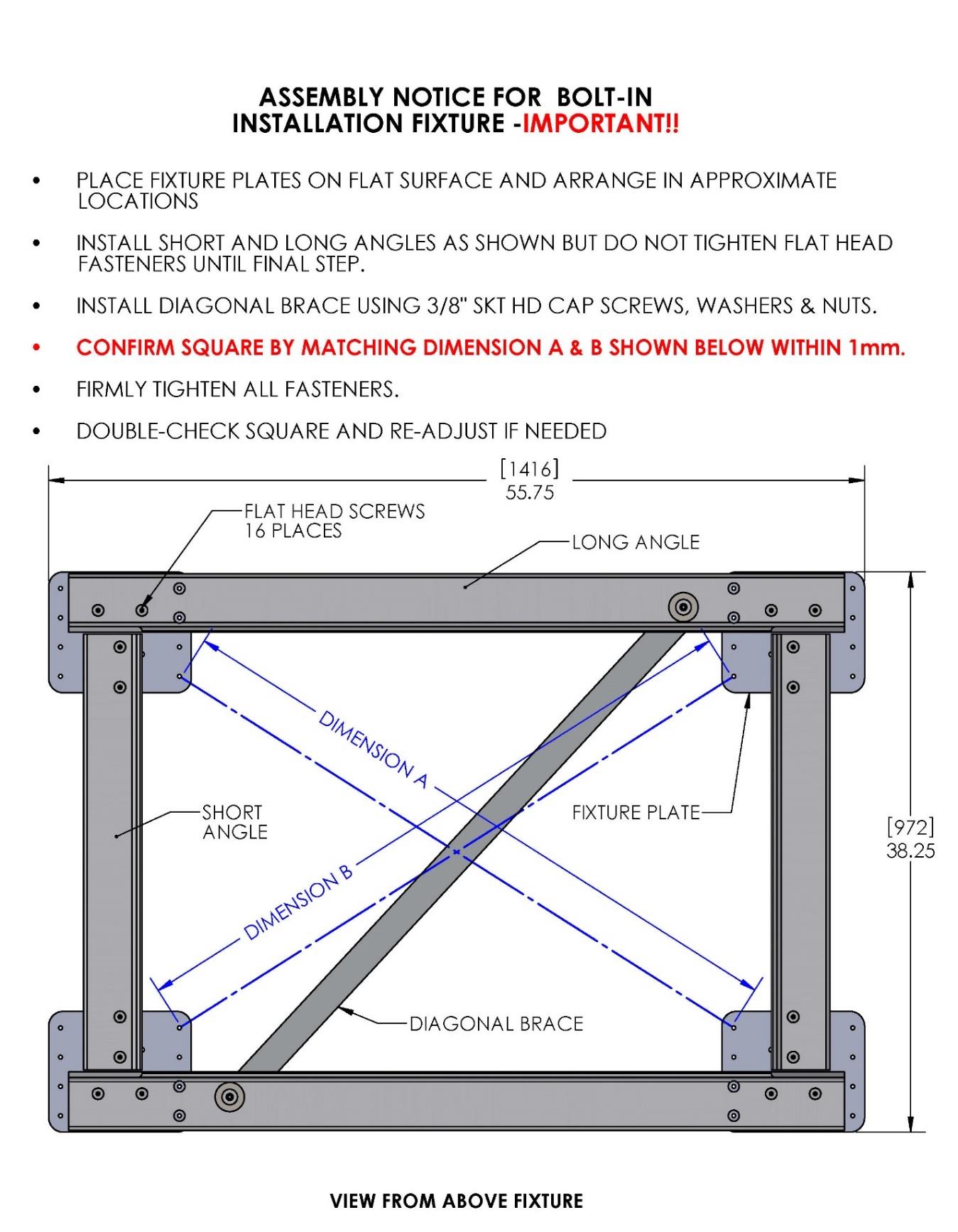
Seakeeper provides an installation fixture assembly (P/N 90089), which contains four plates that mimic the mating surfaces of the four isolation mounts located on the Seakeeper’s foundation. These plates have 8 holes located at the same centers as the holes in the isolation mounts. These smaller holes can be used to locate the holes in the ship’s structure through use of a transfer punch or drill. The fixture locates the hole patterns at the proper spacing, both in the fore-aft direction and the port-starboard direction. See Figures 4 & 5 below. Once assembled, the fixture can be used to check clearances and alignment of the hull structure.
Note: Do NOT use the installation fixture to establish Seakeeper envelope dimensions. Refer to Drawing No. 90714 – Seakeeper 40 Bolt-In Installation Details, for envelope dimensions. A 3-D model of the Seakeeper is available on the Seakeeper website (www.seakeeper.com) to aid in designing the Seakeeper foundation and the space around the Seakeeper.
CAUTION: Tight clearances from cable guide bands to hull structure. See above figure for dimensions and reference Seakeeper Drawing No. 90714 – Seakeeper 40 Bolt-In Installation Details, for complete envelope.