Seakeeper 35 / 30HD Operation Manual (90269-7)
System Overview
System Overview Introduction
The Seakeeper 35 uses gyroscopic principles to reduce boat roll motions in waves and wakes independent of boat speed. In installations involving multiple Seakeepers, each Seakeeper operates independently of one another; therefore this manual only discusses the operation of a single unit.
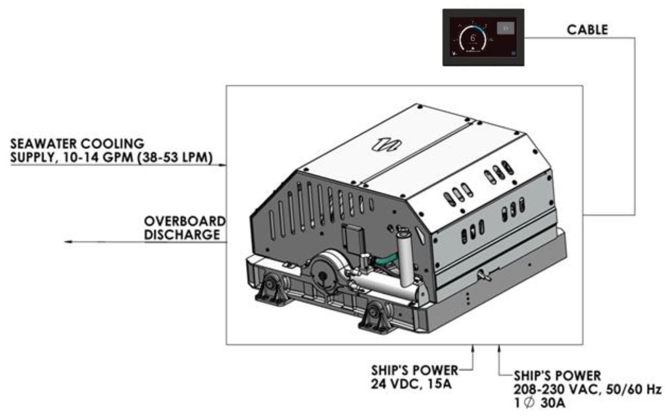
A Seakeeper 35 consists of a Gyro assembly, a CAN communications cable, and a Display. Figure 1 illustrates the interconnection of these components and their interface with the boat.
Seakeeper 35 technical specifications provided in Section: Specifications and Summary, list the power consumption, total weight, and dimensions of the major components. Gyroscopic principals that apply to boat roll control are discussed on Seakeeper’s website at www.seakeeper.com. The Seakeeper website also contains videos of Seakeeper operation and a variety of different boats operating in waves with the Seakeeper on and off. It is recommended that the reader play these videos prior to reading the remainder of this manual.
The gimbal angle and the rate of rotation about the gimbal axis (termed precession rate) play an important role in its operation. These parameters are illustrated in Figure 2. At zero degree gimbal angle, the sphere is vertical; it can precess a maximum of +/- 70 degrees about this position. The amount of torque that the Seakeeper exerts on a boat’s hull to counter the wave induced roll is directly proportional to the precession rate. The farther the Seakeeper is from vertical (zero degrees) the lower the anti-roll torque. The vertical arrows in Figure 2 illustrate the direction of the forces that the Seakeeper exerts on the boat’s hull to damp roll motion.
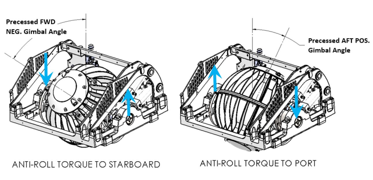
Seakeeper precession is actively controlled by an electronic controller and a hydraulic brake throughout each roll cycle so the Seakeeper supplies the maximum anti-roll torque and does not make mechanical contact with the hard stops that limit the maximum gimbal angle travel to +/- 70 degrees.

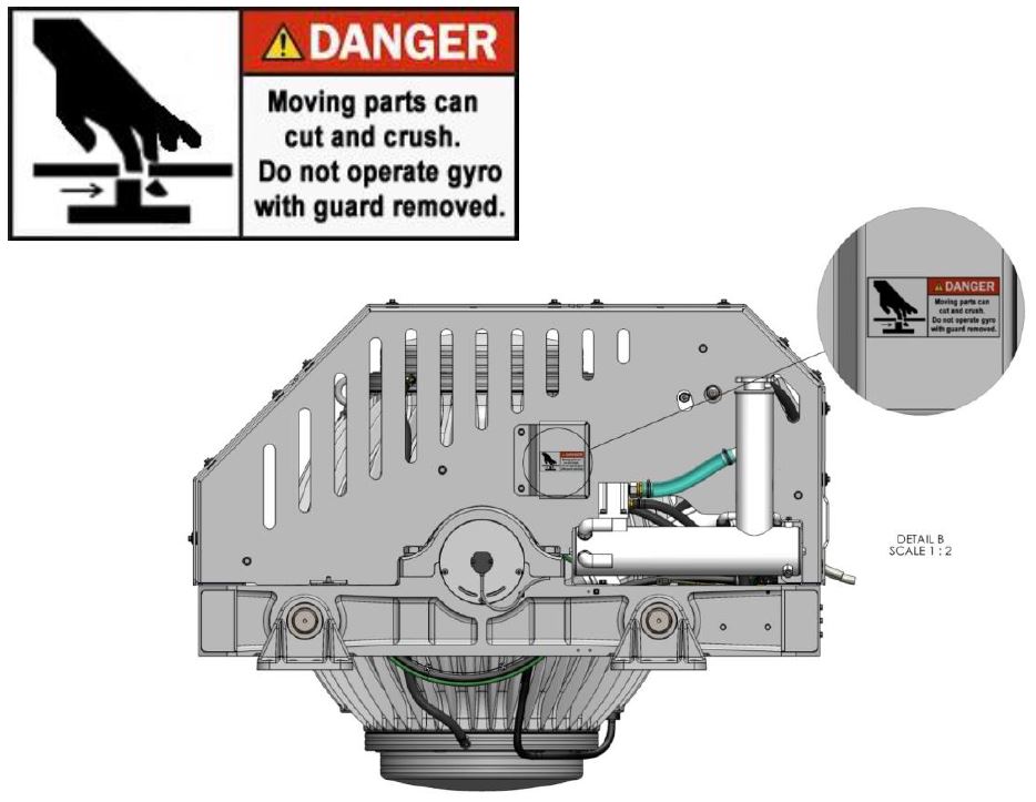
There is a large torque about the gimbal axis when the Seakeeper is precessing. Seakeeper cover panels are provided to prevent personnel or equipment from contacting the Seakeeper while it is in operation. These covers should not be stood on or have anything placed on top. The covers should always be in place during operation. The cover side panels contain safety shields as shown below. Do not operate the Seakeeper without these safety shields in place.
If it is ever necessary to touch the Seakeeper while the flywheel is spinning, the Seakeeper must be locked at the display to stop the Seakeeper from precessing. Seakeeper maintenance should not be attempted unless the Seakeeper is locked and the flywheel has stopped spinning.
Seakeeper Assembly
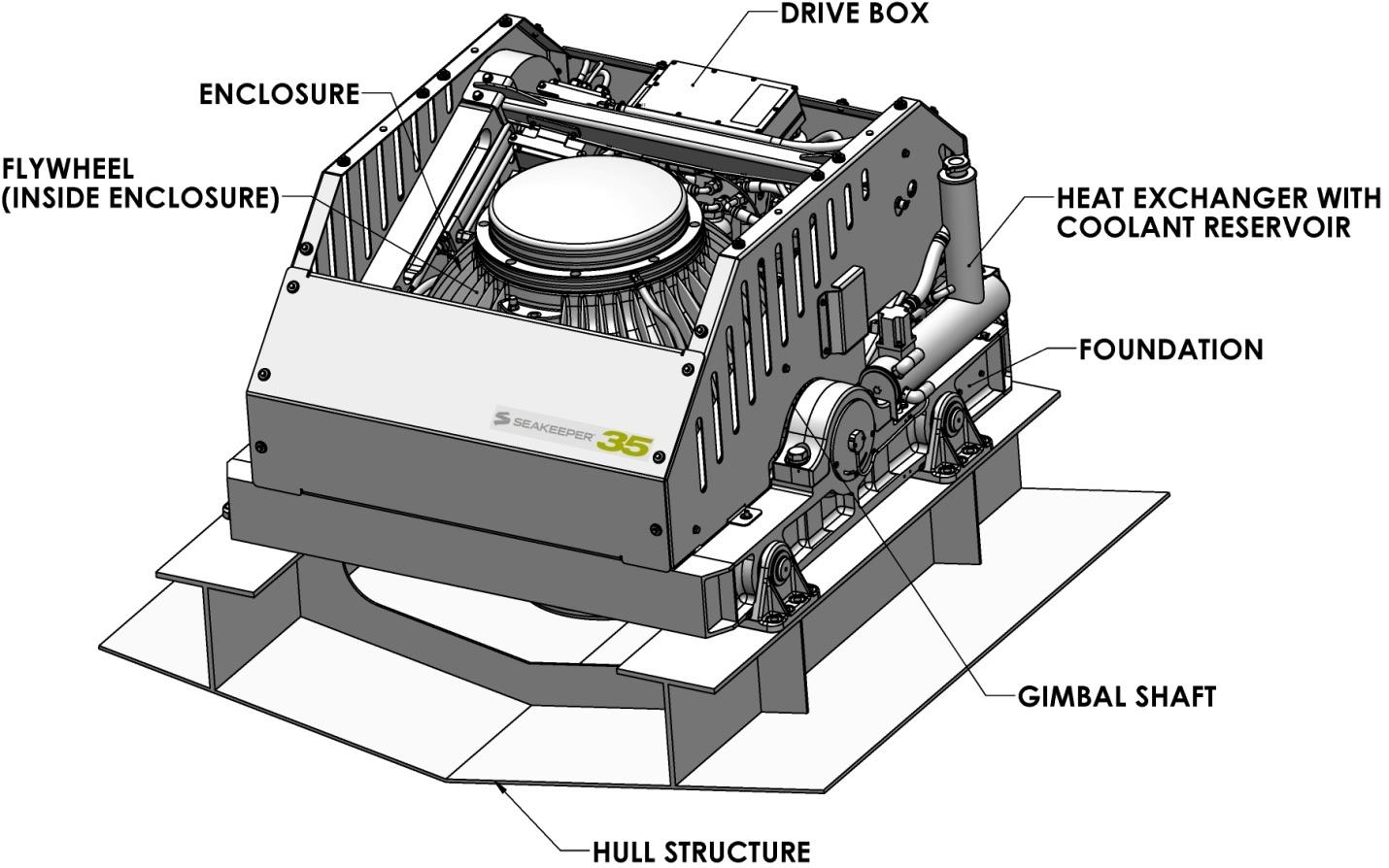
The Seakeeper assembly consists of a flywheel housed in a cast aluminum vacuum-tight enclosure. The flywheel spins about a vertical axis and is supported by upper and lower pairs of bearings. A DC brushless motor mounted inside the enclosure spins the flywheel at high speed.
The enclosure is fastened to two gimbal shafts that are supported by gimbal bearings on either side. These shafts establish an athwartship gimbal axis about which the flywheel and enclosure precess or rotate up to +/- 70 degrees during operation. The gimbal bearings are supported by a foundation which is attached to the hull structure. This foundation transfers the loads that the Seakeeper produces to the hull structure.
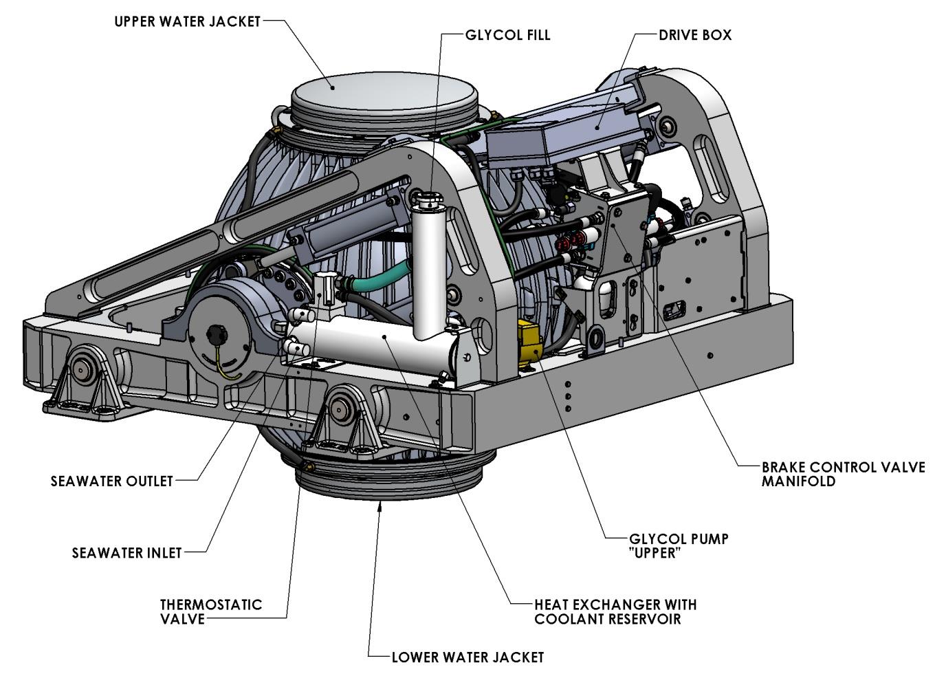
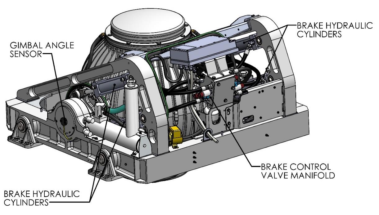
An active hydraulic brake mechanism is located on the Seakeeper assembly to regulate the Seakeeper’s precession motions about the gimbal shaft. It includes four hydraulic cylinders and a hydraulic manifold.
Two coolant pumps, a heat exchanger with reservoir, and thermostat are located near the manifold. The upper pump supplies a glycol/water mix thru a closed loop to the motor drive box and hydraulic manifold, while the lower pump provides coolant to the water jackets of the enclosure to remove heat
Display
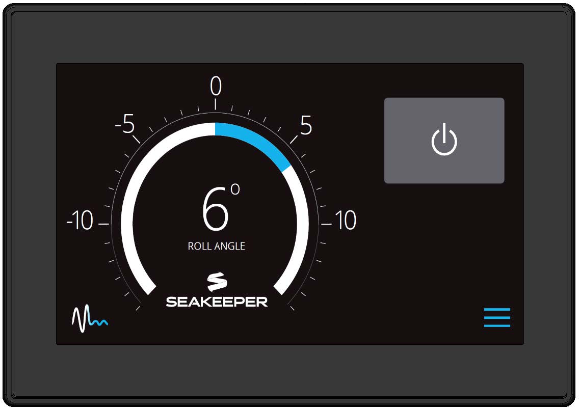
The display shown below is the user interface to the Seakeeper 35 and should be mounted at the primary helm station, unless the vessel has a compatible Multi-Function Display, in which case the Seakeeper Display can be mounted elsewhere. It is used to start, operate, monitor and shutdown the Seakeeper. Sensors, alarms and shutdowns are provided to allow unattended operation. However, the Seakeeper is a high-speed machine and special attention should be paid to abnormal vibration and noise as this could be the first hint of a mechanical problem.
The display provides information in the event of an alarm. Alarms cause precession to stop (Stabilize Off) and the Seakeeper to start coasting down (Seakeeper Off).
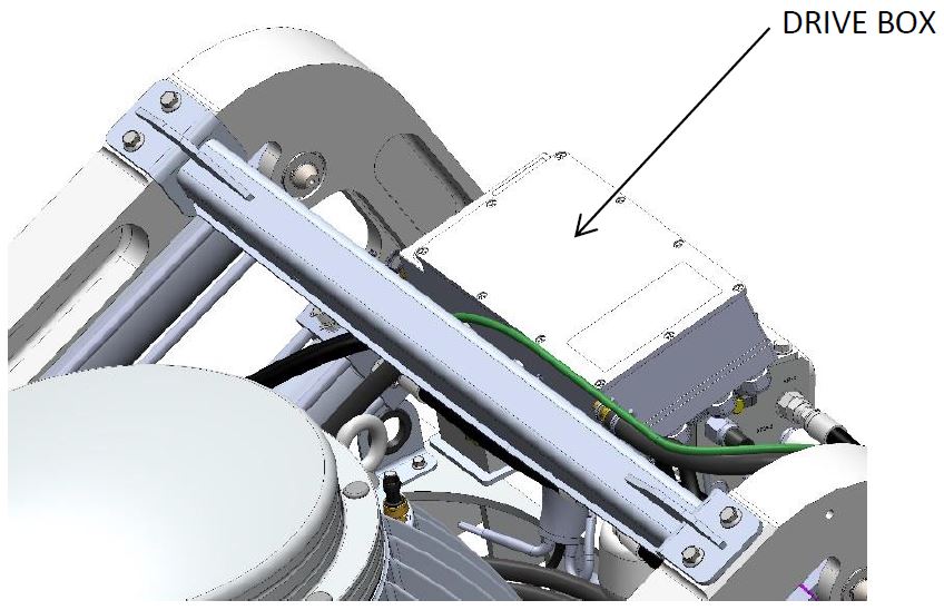
Drive Box
The glycol/water mix that cools the Seakeeper is circulated through a cold plate inside the Drive Box to remove heat from high-power electronic components.
The Motor Drive Box contains hazardous voltage and the cover should not be removed while the flywheel is spinning and the AC input voltage is present. This high voltage exists even if the flywheel is coasting down and the supply voltage has been shut off. The flywheel must be at 0 RPM and AC input power disconnected for at least 10 minutes prior to any service work on the motor drive box.
Electronic Control Module
The Electronic Control Module (ECM) monitors all the system sensors and automatically regulates operation of the Seakeeper.
The controller commands the motor speed and regulates the Seakeeper’s precession rate and gimbal angle. This is accomplished by commands to a high response flow control valve in the hydraulic brake circuit that increases or decreases the brake pressure.
Inertia Measurement Unit
The motion sensor suite in the Inertia Measurement Unit (IMU) measures the angular movements of the vessel and the vertical and lateral boat movement. These signals are communicated to the ECM through the Seakeeper’s wiring harness.
Brake
The brake mechanism consists of four hydraulic cylinders that attach to crank arms on the Seakeeper gimbal shafts. The Seakeeper controller modulates how fast the oil can flow through the control valve thus controlling the precession rate of the Seakeeper.
The brake hydraulic circuit is a pre-charged closed loop – that is, there is no pump, motor or reservoir in the circuit. Accumulators are installed in the circuit so the pre-charge pressure does not increase as the fluid temperature rises due to the braking action. Locking solenoid valves are installed in the circuit to lock the Seakeeper, so it cannot precess if there are any alarms or a mechanical problem.
Hydraulic Hand Pump Kit, P/N 10384, is required for servicing the brake system. Pressure should never be relieved unless this tool is available.
Cooling
The cooling circuit is a closed loop that supplies a glycol/water (50% distilled water and 50% glycol) mix to:
- The motor drive box to remove heat from the drive electronics
- The brake manifold to remove heat from the brake hydraulic circuit
- The enclosure water jackets to remove heat from the flywheel bearings
The heated fluid then passes through a thermostat before bypassing or flowing through a heat exchanger that has seawater on the cold side. The circuit also contains a coolant reservoir for coolant expansion and to make filling easy. The reservoir contains a 7 psi (0.5 bar) pressure cap. The heat exchanger contains zinc anodes that must be inspected and changed regularly to ensure maximum heat exchanger life.