Seakeeper 35 / 30HD Operation Manual (90269-7)
Seakeeper 35 / 30HD Operation Manual (90269-7)
Introduction
Seakeeper 35 / 30HD
Operation Manual
90269, Rev 7
*THIS MANUAL ALSO COVERS THE SEAKEEPER 30HD MODELS*
THIS MANUAL COVERS SEAKEEPER 35 MODELS SERIAL NUMBERS 35-0179 THROUGH CURRENT.
System Overview
System Overview Introduction
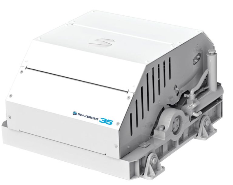
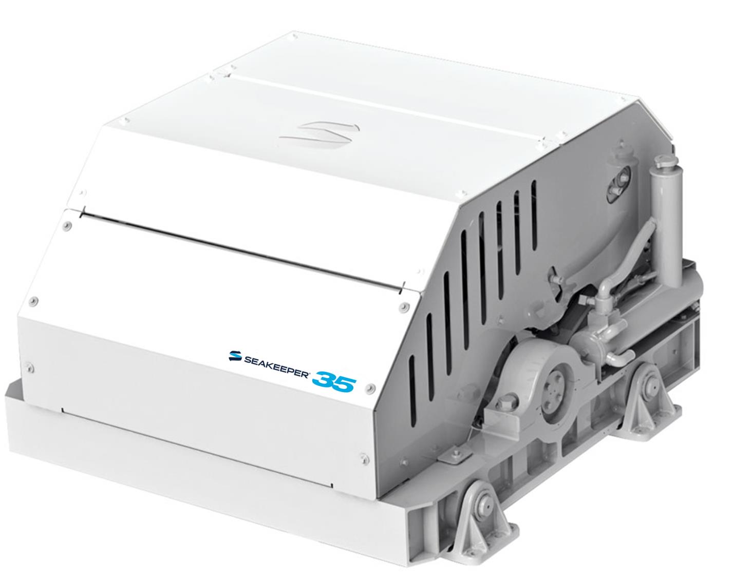
The Seakeeper 35 uses gyroscopic principles to reduce boat roll motions in waves and wakes independent of boat speed. In installations involving multiple Seakeepers, each Seakeeper operates independently of one another; therefore this manual only discusses the operation of a single unit.
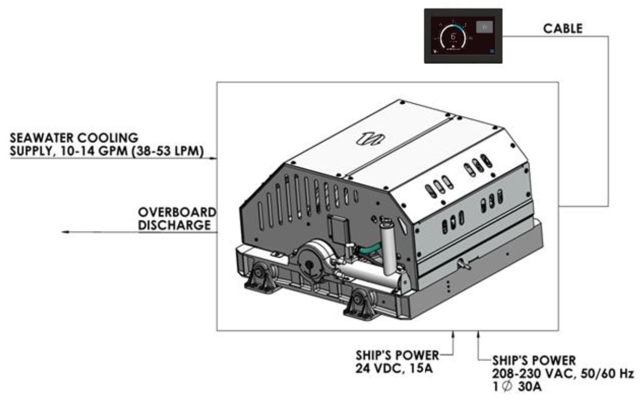
A Seakeeper 35 consists of a Gyro assembly, a CAN communications cable, and a Display. Figure 1 illustrates the interconnection of these components and their interface with the boat.
Seakeeper 35 technical specifications provided in Section: Specifications and Summary, list the power consumption, total weight, and dimensions of the major components. Gyroscopic principals that apply to boat roll control are discussed on Seakeeper’s website at www.seakeeper.com. The Seakeeper website also contains videos of Seakeeper operation and a variety of different boats operating in waves with the Seakeeper on and off. It is recommended that the reader play these videos prior to reading the remainder of this manual.
The gimbal angle and the rate of rotation about the gimbal axis (termed precession rate) play an important role in its operation. These parameters are illustrated in Figure 2. At zero degree gimbal angle, the sphere is vertical; it can precess a maximum of +/- 70 degrees about this position. The amount of torque that the Seakeeper exerts on a boat’s hull to counter the wave induced roll is directly proportional to the precession rate. The farther the Seakeeper is from vertical (zero degrees) the lower the anti-roll torque. The vertical arrows in Figure 2 illustrate the direction of the forces that the Seakeeper exerts on the boat’s hull to damp roll motion.
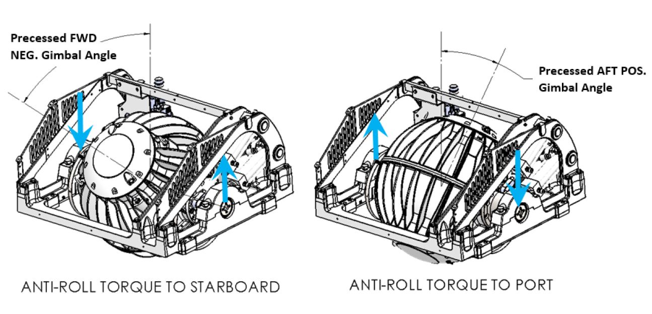
Seakeeper precession is actively controlled by an electronic controller and a hydraulic brake throughout each roll cycle so the Seakeeper supplies the maximum anti-roll torque and does not make mechanical contact with the hard stops that limit the maximum gimbal angle travel to +/- 70 degrees.

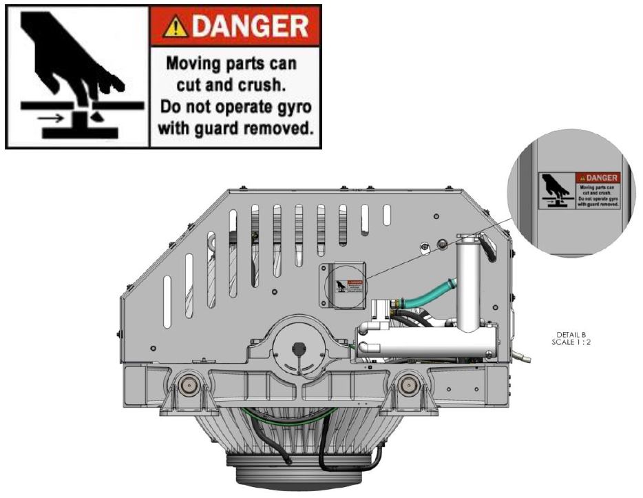
There is a large torque about the gimbal axis when the Seakeeper is precessing. Seakeeper cover panels are provided to prevent personnel or equipment from contacting the Seakeeper while it is in operation. These covers should not be stood on or have anything placed on top. The covers should always be in place during operation. The cover side panels contain safety shields as shown below. Do not operate the Seakeeper without these safety shields in place.
If it is ever necessary to touch the Seakeeper while the flywheel is spinning, the Seakeeper must be locked at the display to stop the Seakeeper from precessing. Seakeeper maintenance should not be attempted unless the Seakeeper is locked and the flywheel has stopped spinning.
Seakeeper Assembly
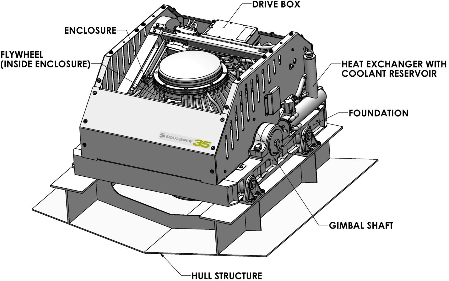
The Seakeeper assembly consists of a flywheel housed in a cast aluminum vacuum-tight enclosure. The flywheel spins about a vertical axis and is supported by upper and lower pairs of bearings. A DC brushless motor mounted inside the enclosure spins the flywheel at high speed.
The enclosure is fastened to two gimbal shafts that are supported by gimbal bearings on either side. These shafts establish an athwartship gimbal axis about which the flywheel and enclosure precess or rotate up to +/- 70 degrees during operation. The gimbal bearings are supported by a foundation which is attached to the hull structure. This foundation transfers the loads that the Seakeeper produces to the hull structure.
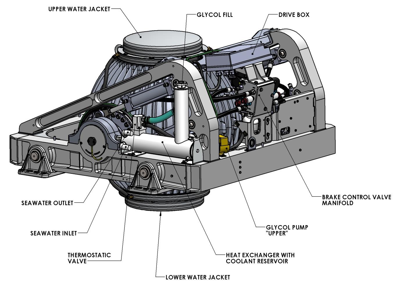
An active hydraulic brake mechanism is located on the Seakeeper assembly to regulate the Seakeeper’s precession motions about the gimbal shaft. It includes four hydraulic cylinders and a hydraulic manifold.
Two coolant pumps, a heat exchanger with reservoir, and thermostat are located near the manifold. The upper pump supplies a glycol/water mix thru a closed loop to the motor drive box and hydraulic manifold, while the lower pump provides coolant to the water jackets of the enclosure to remove heat
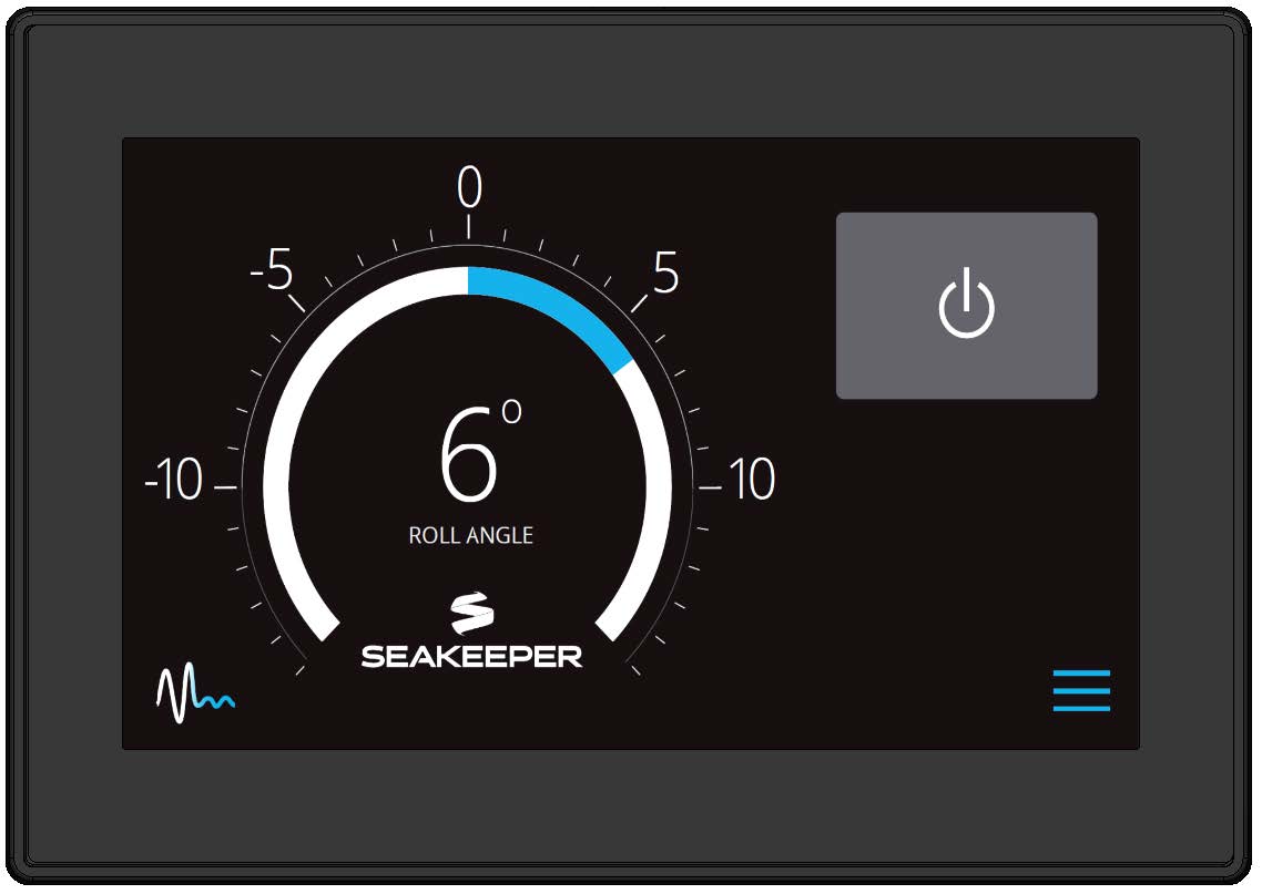
Display
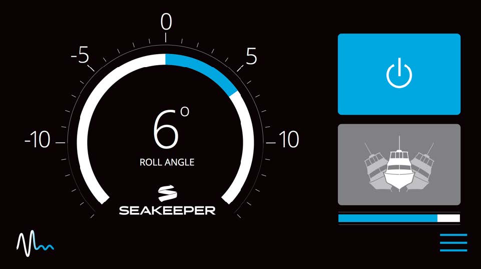
The display shown below is the user interface to the Seakeeper 35 and should be mounted at the primary helm station, unless the vessel has a compatible Multi-Function Display, in which case the Seakeeper Display can be mounted elsewhere. It is used to start, operate, monitor and shutdown the Seakeeper. Sensors, alarms and shutdowns are provided to allow unattended operation. However, the Seakeeper is a high-speed machine and special attention should be paid to abnormal vibration and noise as this could be the first hint of a mechanical problem.
The display provides information in the event of an alarm. Alarms cause precession to stop (Stabilize Off) and the Seakeeper to start coasting down (Seakeeper Off).
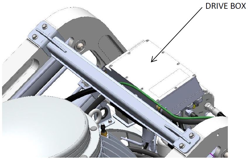
Drive Box
The glycol/water mix that cools the Seakeeper is circulated through a cold plate inside the Drive Box to remove heat from high-power electronic components.
The Motor Drive Box contains hazardous voltage and the cover should not be removed while the flywheel is spinning and the AC input voltage is present. This high voltage exists even if the flywheel is coasting down and the supply voltage has been shut off. The flywheel must be at 0 RPM and AC input power disconnected for at least 10 minutes prior to any service work on the motor drive box.
Electronic Control Module
The Electronic Control Module (ECM) monitors all the system sensors and automatically regulates operation of the Seakeeper.
The controller commands the motor speed and regulates the Seakeeper’s precession rate and gimbal angle. This is accomplished by commands to a high response flow control valve in the hydraulic brake circuit that increases or decreases the brake pressure.
Inertia Measurement Unit
The motion sensor suite in the Inertia Measurement Unit (IMU) measures the angular movements of the vessel and the vertical and lateral boat movement. These signals are communicated to the ECM through the Seakeeper’s wiring harness.
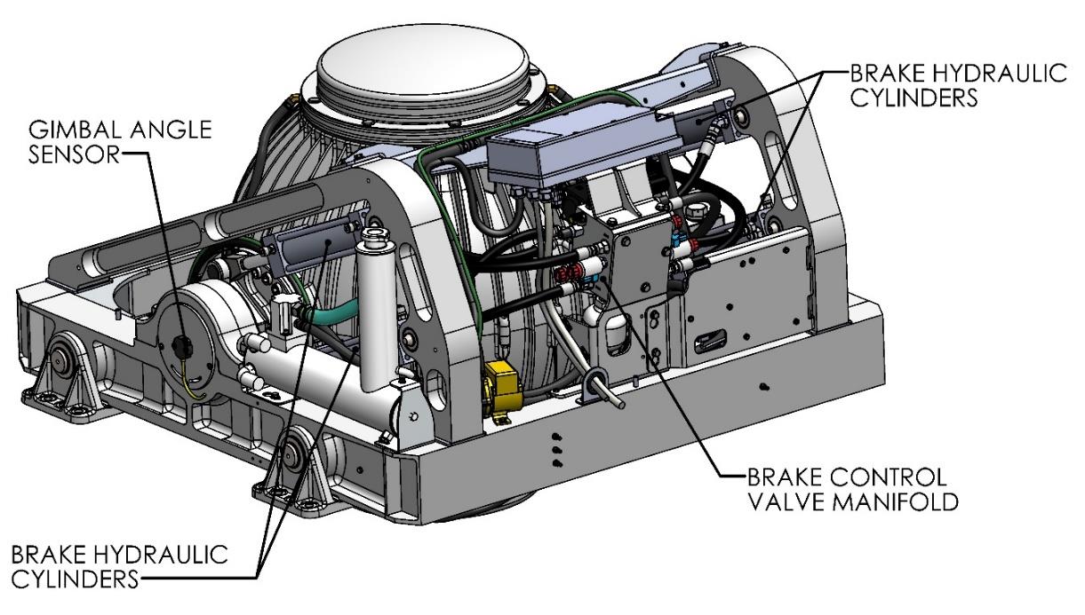
Brake
The brake mechanism consists of four hydraulic cylinders that attach to crank arms on the Seakeeper gimbal shafts. The Seakeeper controller modulates how fast the oil can flow through the control valve thus controlling the precession rate of the Seakeeper.
The brake hydraulic circuit is a pre-charged closed loop – that is, there is no pump, motor or reservoir in the circuit. Accumulators are installed in the circuit so the pre-charge pressure does not increase as the fluid temperature rises due to the braking action. Locking solenoid valves are installed in the circuit to lock the Seakeeper, so it cannot precess if there are any alarms or a mechanical problem.
Hydraulic Hand Pump Kit, P/N 10384, is required for servicing the brake system. Pressure should never be relieved unless this tool is available.
Cooling
The cooling circuit is a closed loop that supplies a glycol/water (50% distilled water and 50% glycol) mix to:
- The motor drive box to remove heat from the drive electronics
- The brake manifold to remove heat from the brake hydraulic circuit
- The enclosure water jackets to remove heat from the flywheel bearings
The heated fluid then passes through a thermostat before bypassing or flowing through a heat exchanger that has seawater on the cold side. The circuit also contains a coolant reservoir for coolant expansion and to make filling easy. The reservoir contains a 7 psi (0.5 bar) pressure cap. The heat exchanger contains zinc anodes that must be inspected and changed regularly to ensure maximum heat exchanger life.
System Operation
Display Screens: Overview
Home Screen & Menu
- When 24 VDC power is applied to the Seakeeper, the display will power up and initialize. The Splash Screen will be displayed.

- After the display has initialized, the Home Screen will be displayed.
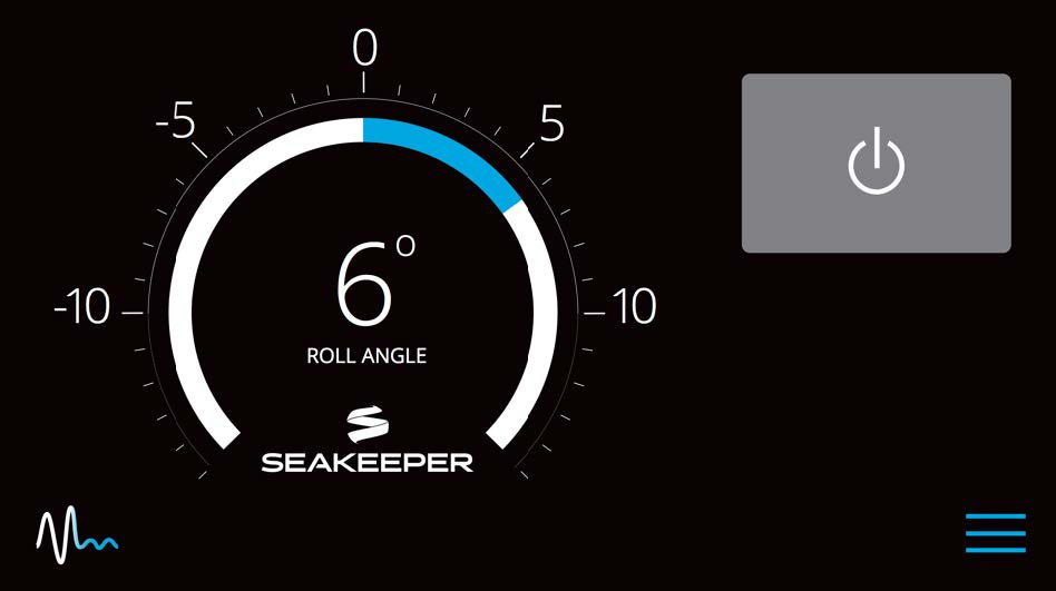
- The display uses a touch screen to allow users to select functions.

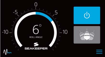
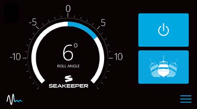
The button will change from grey (Seakeeper Off) to blue (Seakeeper On)
The button will change from grey (Stabilize Off) to blue (Stabilize On)

- When the menu button
 is pressed, the menu bar will appear or disappear at the bottom of the screen.
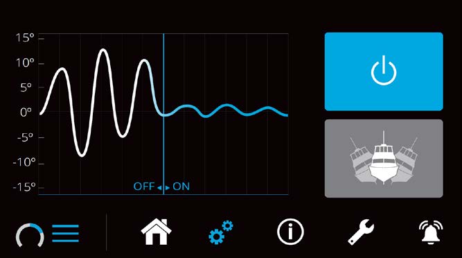
- The menu bar is used to navigate between pages. From left to right, the available pages are home, settings, information, service and alarm history. The selected page is highlighted in blue on the menu bar.

Settings Page
The Settings Page allows the user to adjust their preferences for the display. It can be accessed by pressing the gears ![]() in the menu bar.
in the menu bar.
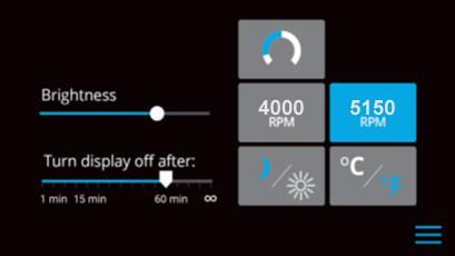
- To increase or decrease the brightness of the display, slide the white dot left to decrease brightness and right to increase brightness on the brightness bar, pictured below on the Settings Page.

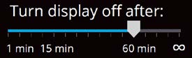
- Adjust the sleep timer from 1 minutes to 60 minutes or on all of the time using sleep time slider. Touching the screen will wake the display up after it has gone to sleep.
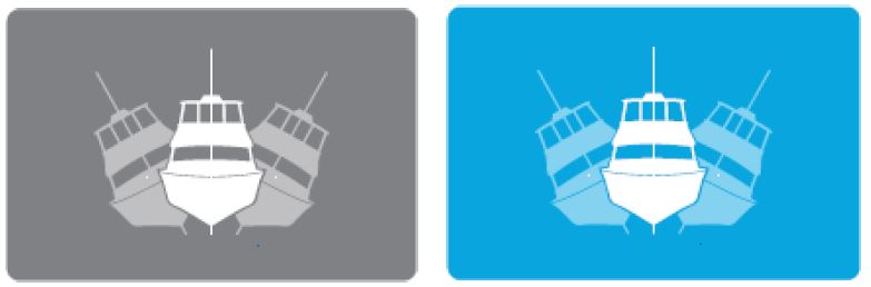
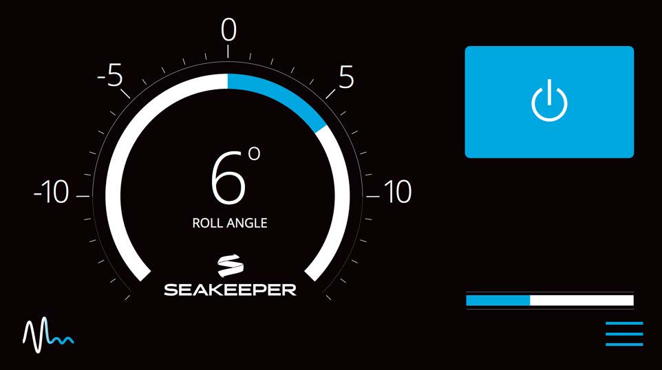
- Change the sign of the roll angle value displayed in the roll angle gauge so the gauge matches the motion of the boat. This will depend on installation orientation and will only need to be adjusted once. If the Seakeeper is facing the bow of the vessel, the Roll Angle Gauge should show the blue on the left (pictured left). If the Seakeeper is facing the stern of the vessel, you should select the Roll Angle Gauge with the blue on the right (pictured right). A positive roll angle should be displayed when the vessel rolls to starboard.

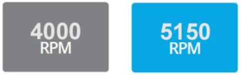
- Change the speed of the Seakeeper between normal operation and low power operation. Low power mode consumes less power and should generate less noise. The selected speed is colored blue. When power is cycled (or Seakeeper turned Off), this speed will default back to the normal operating speed. Speed selection buttons shown below are examples and may not match operating speed of installed Seakeeper.
- Change the display between day and night mode. The selected mode is colored blue and to change between day and night mode, press the button.

- Change the units of the temperatures displayed on the Service Page between degrees Celsius and degrees Fahrenheit. The selected units are colored blue and to change between Celsius and Fahrenheit, press the button.

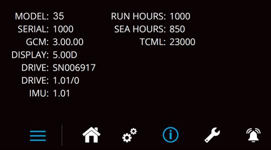
Information Page
- The Information Page
 displays the Seakeeper Model, Serial Number, Software Versions, Run Hours, Sea Hours, and other information. The image below is an example and may not match information details of installed Seakeeper.
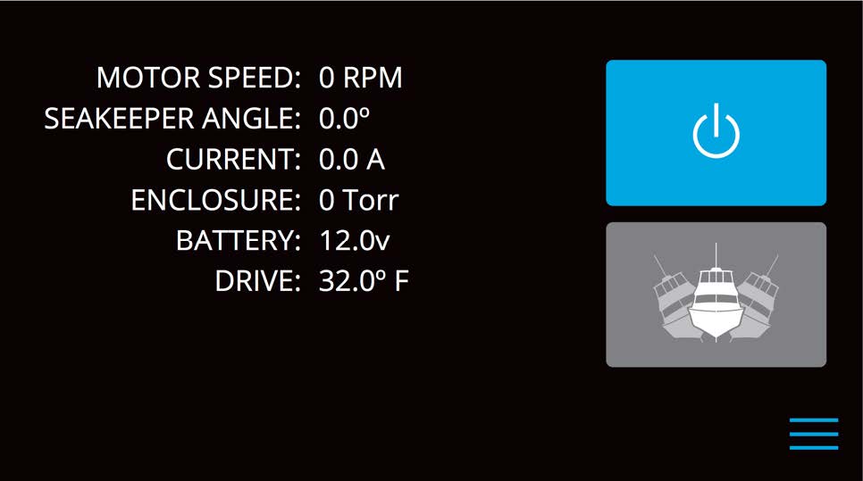
Service Page
- The Service Page
 displays Seakeeper operating information.
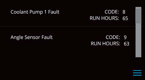
Alarm History Page
- The Alarm History Page
 shows alarms and warnings that have occurred in the past and their associated run hours. The scroll bar on the right is used to move up and down through the list.
Start Up
- Make sure AC and DC power are available.
- Turn on the boat’s DC circuit breaker that supplies power to the Seakeeper.
- Turn on the boat’s AC circuit breaker that supplies power to the Seakeeper.
- In most cases, the seawater pump will be wired to turn on when the Seakeeper is turned on. However, in some cases the seawater pump is on a separate AC or DC circuit breaker and it is necessary to turn it on.
- When the DC power is turned on, the Display will initialize and the Home Screen will appear. If a fault is present an Alarm Screen will appear.
- To turn the Seakeeper on, press the On/Off button, the button will turn blue. The progress bar will appear and indicate how soon the Seakeeper will be available for stabilization. When the Seakeeper is initialized and up to minimum operating speed the Stabilize button will appear. At this point, the Seakeeper is available for stabilization.
- When the Seakeeper reaches its maximum operating speed where maximum stabilization is available, the progress bar will disappear and the Seakeeper is available for maximum stabilization.
Stabilization
To stabilize the vessel after the Seakeeper is On and the flywheel is above the minimum stabilization RPM:
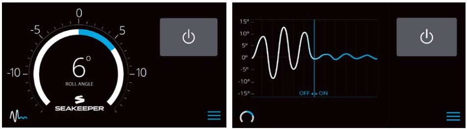
- Press the Stabilize button. The button will turn blue indicating that the Seakeeper is stabilizing the roll motion. The stabilization mode starts gradually; it takes 5-10 seconds to reach full effectiveness.
If it is necessary to shut off power to the flywheel motor and slow the flywheel for any reason, press Seakeeper On/Off button; the button will turn grey and the Stabilize button will disappear, indicating the command has been accepted. It takes approximately 5+ hours for the speed to slow down to 0 RPM.
If it is necessary to stop Seakeeper motion for any reason, press the Stabilize button. The Stabilize button will turn grey indicating that the Seakeeper is locked. Never attempt to work on the Seakeeper until the flywheel has stopped spinning. In the event that the brake system has automatically locked the Seakeeper due to an alarm or failure, no attempt should be made to bypass the alarm or automatic lock.
Normal Shut Down
The Seakeeper should be stopped when pulling into port and stabilization is no longer required. This maximizes life by allowing the Seakeeper to start the coast down cycle before cooling is shutoff. Once the vessel is secured, the AC and DC breakers can be switched Off. The Seakeeper will continue to spool down to 0 RPM. No cooling is required during this time.
Note: The seawater pump may run for 5 minutes after the Seakeeper is switched off and is coasting (with AC power applied).
- Press the Seakeeper On/Off button. The On/Off button will turn grey. The Seakeeper will discontinue stabilization and the flywheel will start coasting.
- Once the vessel is secured in the slip and the crew has shut down the generator and engines, switch the AC and DC breakers that control the Seakeeper Off. The flywheel will continue to spool down to 0 RPM. This can take 5+ hours from full speed. When the flywheel has stopped spinning, 0 RPM will appear on the screen.
The circuit breakers should be left on as long as possible while the Seakeeper is spinning to remove heat from the Seakeeper. During normal operation, the Seakeeper should be stopped when pulling into port and stabilization is no longer required. This maximizes long term life as it allows the Seakeeper to start the coast down cycle before cooling is shutoff. Once the vessel is secured in the slip and the crew has shut down the generator and engines, the AC and DC breakers that control the Seakeeper should be switched to the Off position. The Seakeeper will continue to spool down to 0 RPM. No cooling is required during this time. Note Seakeeper will take approximately 5+ hours to coast down to 0 RPM from full speed. The Display will indicate 0 RPM when the flywheel has stopped.
Note: The seawater pump may run for up to 5 minutes after the Seakeeper is switched off and is coasting (with AC power applied).
Speed Adjustment
When cruising without Seakeeper stabilization, run the Seakeeper at 1000 RPM to maintain lubrication of the bearings. The Seakeeper will use less than 300 W of AC power while operating in this mode.
- Press the Menu button
 , then select the Settings screen
  .
. - Select the desired RPM button to adjust the Seakeeper’s speed. The selected RPM button will turn blue. Speed selection buttons shown below are examples and may not match operating speed of installed Seakeeper.
- Seakeeper 35: Normal operational speed is 5150 RPM. Quiet mode operates at 4000 RPM, which allows stabilization at a reduced flywheel speed. After a 24 V power cycle to the Seakeeper, the speed selection will revert to 5150 RPM.
- Seakeeper 30HD: Normal operational speed is 4400 RPM. Quiet mode operates at 3500 RPM, which allows stabilization at a reduced flywheel speed. After a 24 V power cycle to the Seakeeper, the speed selection will revert to 4400 RPM.
Power Failures, Alarms, and Troubleshooting
Power Failures
There are two sources of power to the Seakeeper 35:
- 24 VDC powers the Seakeeper for all the control electronics.
- 208 – 230 VAC powers the Motor Drive Box to drive the motor inside the Seakeeper.
These are supplied on Cables 1 and 2 which are shown on Drawing No. 90288 – Seakeeper 35 / 30HD Cable Block Diagram.
The Motor Drive Box contains hazardous voltage and the cover should not be removed while the flywheel is spinning and the AC input voltage is present. This high voltage exists even if the flywheel is coasting down and the supply voltage has been shut off. The flywheel must be at 0 RPM and AC input power disconnected for at least 10 minutes prior to any service work on the motor drive box.
24 VDC Failure
If the 24 VDC is disconnected during operation, the display will be blank, flywheel speed will decrease, and the brake will be locked (no precession).
- Verify the boat’s circuit breaker supplying +24 VDC has not tripped and the AC breaker is On.
- When +24 VDC is restored, the display will power up, the Splash Screen will appear, and then the Home Screen will appear.
- Press Power On/Off button
 . The progress bar will appear and indicate flywheel speed. When the flywheel is at minimum operating speed, the Stabilize button will appear so stabilization can be turned on. This may take up to 30 minutes, depending on the speed of the flywheel when the +24 VDC is turned back on.
230 VAC Failure
If the AC power is not connected, a notification screen will indicate “AC Mains Low”. If the failure is not corrected within two minutes, an “AC Mains Low” alarm will occur. The brake will lock and the Seakeeper will stop moving if stabilization was on.
- Verify the boat’s circuit breaker supplying 208-230 VAC to the Motor Drive Box has not tripped.
- When 208-230 VAC is restored, the display will power up, the Splash Screen will appear, and then the Home Screen will appear.
- Press Power On/Off button to clear the alarm. The progress bar will appear and indicate flywheel speed. When the flywheel is at minimum operating speed, the Stabilize button will appear so stabilization can be turned on. This may take up to 30 minutes, depending on the speed of the flywheel when the 208-230 VAC is turned back on.
230 VAC Fluctuation, Spike, or Momentary Failure
If the AC voltage to the Motor Drive Box is outside Seakeeper’s specified range (208 – 230 VAC), the Motor Drive Box will briefly shut down for protection. The Motor Drive Box will continue operation when the voltage returns to the specified range.
A brief fluctuation can happen when the generator is unable to regulate its output voltage, particularly when a large AC load is switched on or off. A momentary AC failure also happens during transition from shore power to ship’s power.
Alarms
The Seakeeper issues an alarm when it detects a malfunction that could cause damage or erratic operation. When an alarm occurs, the Seakeeper will stop and an alarm message is shown on the Display.
The alarm will not clear until the operator presses the Reset Alarm button and the alarm condition is no longer present. The operator can then press the Power On/Off button again to continue Seakeeper operation.
- A view of a typical Alarm screen.
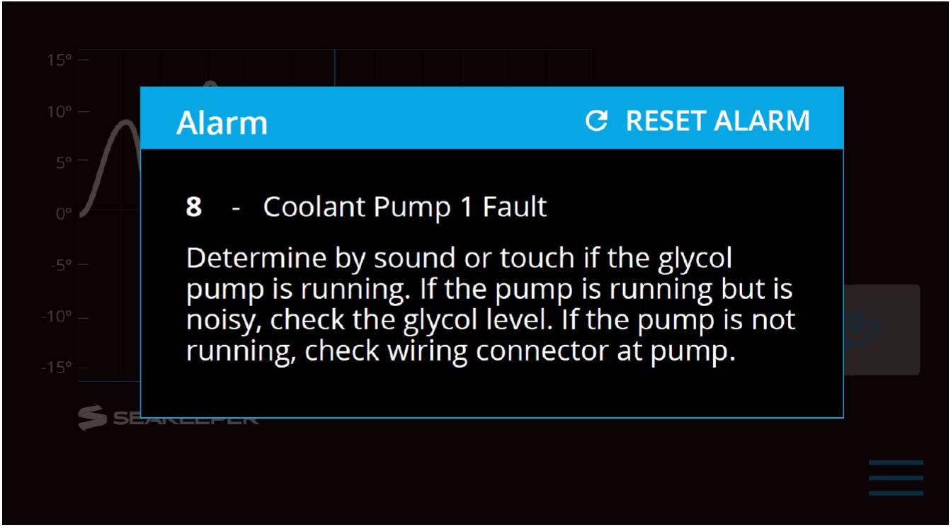
- To reset the alarm, press the Reset Alarm button:

Alarm History
The Alarm History page on the Display shows the recent alarms and warnings. The alarms are in chronological order starting with the most recent. Warnings included in the history page are for issues that do not affect Seakeeper operation.
Press the Menu button ![]() to show the page options and then the Alarm button
to show the page options and then the Alarm button ![]() to show alarm history.
to show alarm history.
Maintenance
Maintenance Introduction
The Seakeeper system is designed to require as little maintenance as possible. However, since the system is comprised of mechanical and electrical components that operate in a marine environment, some periodic inspections and maintenance are required. Seakeeper recommends a regular inspection interval and Scheduled Maintenance to keep the Seakeeper running trouble-free.
If the Seakeeper is installed in a wet space, efforts should be made to keep the Seakeeper free of salt residue from either condensation or direct exposure to salt spray. If exposed, a regular wipe down with mild soap and water with a rinse will help limit corrosion and keep the Seakeeper assembly in good cosmetic condition. Refer to How to Care for Your Seakeeper article for details.
If any components of the Seakeeper or its sub-systems will be exposed to environmental temperatures where winterization is necessary for storage, reference How Do I Winterize My Seakeeper? article for details.
The Seakeeper comes standard with sealant and thread locker on applicable fasteners. When reinstalling all fasteners use thread locker and sealant unless otherwise specified.
Reference Documents:

Due to remote start capabilities of MFDs, ENSURE power removed from Seakeeper and flywheel at zero RPM at display/MFD app before removing covers.
Hydraulic Hand Pump Kit is required for servicing the brake. Pressure should NOT be relieved unless this tool is available.
Scheduled Maintenance Table
This page contains the scheduled maintenance table organized by systems: Mechanical, Hydraulic, Cooling, and Electrical. Scheduled maintenance is not covered under warranty.
- Scheduled Maintenance should be performed by a Seakeeper trained factory technician or trained technician within the Seakeeper Dealer network. Find a local Dealer on our website at www.seakeeper.com/find-us/.
- A Seakeeper technician or Dealer is required to perform a brake service and to replace brake bushings or other brake components. This requires a complete flush, bleed, purge and pressurization of the closed hydraulic system.
- Scheduled Maintenance and the replacement of ‘wear’ items are not covered by the www.seakeeper.com/extended-warranty/recreation-warranty/.
| System / Component | Task | Interval | Parts / Special Tools |
|---|---|---|---|
| Mechanical / Corrosion | Inspect unit for severely corroded areas and clean and touch up with paint. See Service Bulletin 90026 – Seakeeper Paint Information. | 12 Months or 1000 Hours | Awlgrip Paint P/N’s: Primer: S9001 Primer Converter: S3001 Top Coat, Snow White: F8063 Top Coat Converter: G3010 |
| Hydraulic / Hoses | Check for cracks or chafing. If chafing found, reposition hose to provide clearance around hose. If chafing is severe, replace hose. Charge system per Service Bulletin 90025 – Brake Bleeding. | 12 Months or 1000 Hours | Hydraulic Hand Pump Kit |
| Cooling / Zinc Anode | Replace zinc anode as needed. Note the wear rate after each check and adjust inspection interval accordingly. | 3 Months or 150 Hours | Replacement Zincs are available from Seakeeper. |
| Cooling / Hoses | Check for cracks or chafing. If damaged, replace hose. Fill cooling system and purge air. | 12 Months or 1000 Hours | Anti-freeze – 50/50 Ethylene Glycol mix. |
| Cooling / Seawater side | Inspect heat exchanger for signs of leaks. | 3 Months or 150 Hours | |
| Cooling / Seawater side | Fill with environmentally safe, marine anti-freeze during winter or periods of in-operation. | Winter | |
| Electrical / Connectors | Inspect all connectors for corrosion, replace if necessary. | 12 Months or 1000 Hours | |
| Electrical / Grounds | Inspect all ground points for corrosion, clean as necessary, and treat with corrosion inhibitor. | 12 Months or 1000 Hours | |
| Electrical / Gimbal Angle Sensor | Check calibration of sensor. See Service Bulletin 90083 – Gimbal Angle Sensor Replacement and Calibration, for instructions. | Only if Angle Alarms occur | |
| Electrical / Cables | Check all cables and wire harness branches for cracks or chafing. Take special attention to gimbal shaft areas. | 12 Months or 1000 Hours | |
| Electrical / Power Input | Check for seal at cable glands. | 12 Months or 1000 Hours | |
| Electrical / Motor Power | Check integrity of motor power cable jacket. | 12 Months or 1000 Hours | |
| Mechanical / Hydraulic Brake | Replace brake bushings, hydraulic accumulators and check valves | Inspect at 12 Months or 1000 Hours – Replace as needed or at 2000 Hours | Hydraulic Hand Pump Kit, Brake Bushing Replacement Tool Kit, Hydraulic Brake Parts Kit |
| Mechanical / Hydraulic Brake | Flush Hydraulic Oil | 12 Months or 1000 Hours | Hydraulic Hand Pump Kit Oil: AW46 |
| Mechanical / Foundation | Inspect all four mounts on foundation frame for excess wear and play in operation – contact Seakeeper service if any slop in pin joint is detected. | 12 Months or 1000 Hours | |
| Cooling / System | Cooling system flush | 12 Months or 1000 Hours | Fill reservoir, antifreeze – 50/50 Ethylene Glycol mix |
Warranty, Limit of Liability, Property Rights
Warranty
The complete Seakeeper warranty details may be found on the Seakeeper website www.seakeeper.com.
Seakeeper Standard Models
SEAKEEPER warrants that the Goods sold hereunder are free from defects in material and workmanship. This warranty is for the following period, whichever occurs first:
- 36 months (3 years) from the date of shipment from SEAKEEPER factory.
- 24 months (2 years) from date the product was put into service, which shall conclusively be presumed to be the date of sale of a vessel, on which a SEAKEEPER product is installed, to a retail customer or date put into service on an existing vessel (refit).
- Or, 2,000 (two thousand) hours of use, subject to verification and confirmation by SEAKEEPER, INC.
Seakeeper Heavy Duty Models
SEAKEEPER warrants that the Goods sold hereunder are free from defects in material and workmanship. This warranty is for the following period, whichever occurs first:
Major Components (Sphere):
- 48 months (4 years) from date the product was put into service, which shall conclusively be presumed to be the date of sale of a vessel, on which a SEAKEEPER product is installed, to a retail customer or date put into service on an existing vessel (refit).
- Or, 4,000 (four thousand) operating SEA hours, subject to verification and confirmation by SEAKEEPER, INC.
All Other Components:
- 24 months (2 years) from date the product was put into service, which shall conclusively be presumed to be the date of sale of a vessel, on which a SEAKEEPER product is installed, to a retail customer or date put into service on an existing vessel (refit).
- Or, 2,000 (two thousand) hours of use, subject to verification and confirmation by SEAKEEPER, INC.
All Seakeeper Models
This warranty does not cover normal wear of the following components or the costs associated with maintenance, repair or replacement:
- Surface Corrosion (Cosmetic) on any component due to exposure
- Heat Exchanger
- Zinc Anodes
- Brake Bushings
- Isolation Bushings
- Normal preventive and scheduled maintenance and component inspections/replacements as specified in the SEAKEEPER, INC., Operation Manuals and any other Maintenance Schedule documentation.
This express warranty is in lieu of and excludes: ALL OTHER WARRANTIES, EXPRESSED OR IMPLIED, BY OPERATION OF LAW OR OTHERWISE INCLUDING WARRANTIES OF MERCHANTABILITY OR FITNESS FOR A PARTICULAR PURPOSE (WHETHER KNOWN TO SELLER OR NOT), AND ALL OTHER SUCH WARRANTIES ARE HEREBY EXPRESSLY DISCLAIMED BY SELLER AND WAIVED BY CUSTOMER/END USER. SEAKEEPER, INC. SHALL IN NO EVENT BE LIABLE TO ANY SPECIAL, DIRECT, INDIRECT, INCIDENTAL OR CONSEQUENTIAL DAMAGES FOR BREACH OF ANY WARRANTY OR OTHER OBLIGATION ARISING OUT OF THE SALE OF THE PRODUCTS, OR FROM THE USE OF THE PRODUCTS OR ANY INABILITY TO USE THE PRODUCTS.
Written notice of claimed defects shall have been given to SEAKEEPER within the Warranty Period, and within thirty (30) days from the date any such defect is first discovered. The Goods or parts claimed to be defective must be returned to SEAKEEPER, accompanied by a Return Authorization (RA) issued by SEAKEEPER’s facility responsible for supplying Goods, with transportation prepaid by Buyer/User, with written specifications of the claimed defect.
If a warranty claim is valid, SEAKEEPER, INC. will repair or replace the Product, or part of the Product, proven to be defective, at its sole discretion, in a timeframe provided by SEAKEEPER, INC., on a reasonable best effort basis.
Under no circumstances shall SEAKEEPER be liable for removal of SEAKEEPER’s Goods from Buyer’s/User’s equipment or re-installation into Buyer’s/User’s equipment. No person including any agent, distributor, or representative of SEAKEEPER is authorized to make any representation or warranty on behalf of SEAKEEPER concerning any Goods manufactured by SEAKEEPER.
Warranty Activation
A Warranty Registration must be fully completed and sent to SEAKEEPER, INC., for review, approval and registration upon delivery of the vessel to the first retail customer. Warranty registration and expiration date confirmation can be achieved by providing SEAKEEPER, INC., a copy of the original bill of sale, purchase agreement, Owner’s name, address and SEAKEEPER Stabilizer Serial Number along with current RUN / SEA hours to SEAKEEPER’s warranty registration department within thirty (30) days of purchase. For removal of doubt, it is clarified that the activation date shall in no event affect the warranty period set forth herein.
“Owner” is defined as the first retail customer (purchaser), or subsequent customer (by transfer), of the SEAKEEPER Product as identified in SEAKEEPER warranty registration(s).
Limitation of Liability
NOTWITHSTANDING ANYTHING TO THE CONTRARY, SEAKEEPER SHALL NOT BE LIABLE FOR ANY SPECIAL, INCIDENTAL, INDIRECT OR CONSEQUENTIAL DAMAGES INCLUDING BUT NOT LIMITED TO LOST PROFITS ARISING OUT OF THE PERFORMANCE, DELAYED PERFORMANCE OR BREACH OF PERFORMANCE OF THIS ORDER REGARDLESS WHETHER SUCH LIABILITY BE CLAIMED IN CONTRACT, EQUITY, TORT OR OTHERWISE. SEAKEEPER’S OBLIGATION IS LIMITED SOLELY TO REPAIRING OR REPLACING (AT ITS OPTION AND AS SET FORTH IN SECTION 5), AT ITS APPROVED REPAIR FACILITY, ANY GOODS OR PARTS WHICH PROVE TO SEAKEEPER’S SATISFACTION TO BE DEFECTIVE AS A RESULT OF DEFECTIVE MATERIALS OR WORKMANSHIP, IN ACCORDANCE WITH SEAKEEPER’S STATED WARRANTY. IN NO EVENT SHALL SEAKEEPER’S LIABILITY EXCEED THE TOTAL PURCHASE PRICE SET FORTH IN THIS ORDER.
Property Rights
Except where otherwise expressly agreed, all patterns, tools, jigs and fixtures, drawings, designs, software and other materials and data developed, fabricated by Seakeeper shall be and shall remain Seakeeper‘s property. Except as specifically provided for in the order, Buyer shall have no right in any technical data, Intellectual Property Rights, and computer software associated with the order. Buyer shall not use or permit the use of the Goods that in any way could result in the disclosure of Seakeeper‘s proprietary information.
Specifications and Summary
| Seakeeper 35 | Seakeeper 30HD | |
|---|---|---|
| Rated RPM | 5,150 RPM | 4,400 RPM |
| Angular Momentum at Rated RPM | 35,000 N-m-s | 30,000 N-m-s |
| Anti-Rolling Torque at Rated RPM | 73,000 N-m | 62,571 N-m |
| Spool-up Time to Rated Speed | 65 minutes (5,150 RPM) | 75 minutes (4,400 RPM) |
| Spool-up Time to Stabilization | 45 minutes (4,380 RPM) | 50 minutes (3,500 RPM) |
| Spool-up Power AC Motor DC Control | 5,000 Watts Max 240 Watts | 3,000 Watts Max 240 Watts |
| Operating Power AC Motor (Sea state dependent) DC Control | 2,000-5,000 Watts 240 Watts | 2,000-3,000 Watts 240 Watts |
| Voltage AC Input DC Input | 208-230 VAC (±10%), 50/60 Hz, Single Phase, 30 A 24 VDC @ 15 Amps | 208-230 VAC (±10%), 50/60 Hz, Single Phase, 20 A 24 VDC @ 15 Amps |
| Seawater Supply to Heat Exchanger | 14 GPM (53 LPM) maximum 10 GPM (38 LPM) minimum | 14 GPM (53 LPM) maximum 10 GPM (38 LPM) minimum |
| Ambient Air Temperature | 32˚ – 140˚F (0 – 60˚C) | 32˚ – 140˚F (0 – 60˚C) |
| Weight | 3,920 lbs (1,778 kg) bolt-in | 3,920 lbs (1,778 kg) bolt-in |
| Envelope Dimensions | 54.3 L x 55.9 W x 43.5 H (inches) 1.38 L x 1.42 W x 1.11 H (meters) | 54.3 L x 55.9 W x 43.5 H (inches) 1.38 L x 1.42 W x 1.11 H (meters) |
| Noise Output | At full operating RPM, steady state noise measured in the factory at a 1-meter distance measures 72-74 dBC (sound levels may be higher during spool-up). | At full operating RPM, steady state noise measured in the factory at a 1-meter distance measures 72-74 dBC (sound levels may be higher during spool-up). |
Arrangement
The Seakeeper 35 consists of the Flywheel, Enclosure, Foundation, Electronics, Brake, Cooling, and Cover Subsystems.
Installation Location
The Seakeeper is a torque device and does not have to be installed in a specific hull location or on the centerline. However, the Seakeeper should not be installed forward of the longitudinal center of gravity in a planing vessel.
Mounting Dimensions
See Drawing No. 90256 – Seakeeper 35/30HD Bolt-In Installation Details.
See Drawing No. 90255 – Seakeeper 35/30HD Bond-In Installation Details.
Loads
The installer is responsible for designing the foundation to which the Seakeeper is attached and for ensuring that this foundation can safely transfer the concentrated Seakeeper loads from the frame to the adjacent hull structure. Loads that the Seakeeper imposes on the hull structure are explained on Drawing No. 90256 – Seakeeper 35/30HD Bolt-In Installation Details and Drawing No. 90255 – Seakeeper 35/30HD Bond-In Installation Details; these loads do NOT include vessel motion accelerations, such as vertical slam loads which can be high for higher speed vessels.
Cooling
The Seakeeper bearings, Motor Drive Box, and hydraulic manifold are cooled by a closed water / glycol mix cooling loop that incorporates a seawater heat exchanger. The installer is responsible for providing 10 – 14 GPM (38 – 53 LPM) raw water at ambient sea temperature and a maximum pressure of 20 psi (1.4 bar) to the heat exchanger.
Electrical
The installer is responsible for supplying 208-230 VAC, 50/60 Hz, single phase power on a (30 A for Seakeeper 35; 20 A for Seakeeper 30HD) service to the Motor Drive Box and 24 VDC at 15 A service to the Seakeeper Control System. Separate circuit breakers should be used for each Motor Drive Box in multiple Seakeeper installations. Similarly, separate circuit breakers should be used for each Seakeeper Control System in multiple Seakeeper installations.
Operator Controls
A Display with integrated Keypad is used to start, operate, monitor, and shutdown the Seakeeper.
Performance
Reduction of boat roll is a function of the boat’s displacement, transverse metacentric height (GMT) and hull damping as well as the operating conditions (speed and heading with respect to waves) and sea state. The Seakeeper controller regulates the active hydraulic brake to ensure the Seakeeper’s anti-roll torque is maximized regardless of hull characteristics or operating conditions.
Alarm and Monitoring
Sensors, alarms and shutdowns are provided to allow unattended operation. Sensors measure Seakeeper and drive temperatures, vacuum pressure, gimbal angle, brake pressure, and ship motion. The Seakeeper controller sends sensor values and alarm information to the display and also locks the brake and shuts down the motor drive in the event of an alarm condition. Seakeeper operating history during faults or alarms is recorded in the controller’s memory for subsequent recall if service is needed. Seakeeper may access the Seakeeper’s software to gather run hours, bearing loading, and hull slamming information.
Safety
The brake automatically locks the Seakeeper so it cannot generate excessive anti-rolling torque loads in the event of a system fault or alarm, loss of electrical power or loss of brake pressure. The brake can be locked from the Display or by shutting off AC and DC power at the supply breakers.