Seakeeper 3 Installation Manual (90378-7); S/N 3-232-4223 to Current
1.0 Introduction
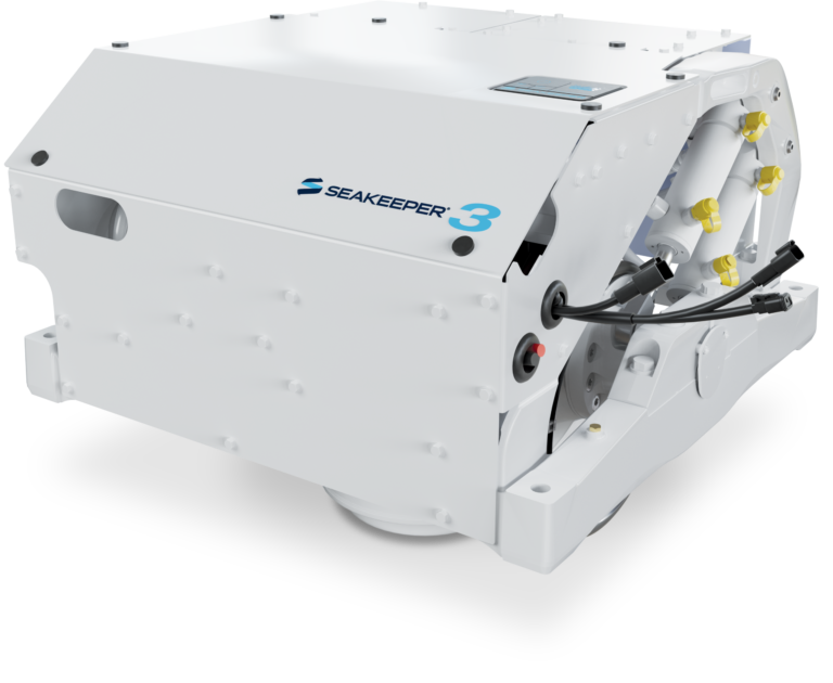
Seakeeper 3
Installation Manual
90378, Revision 7
This document is intended to give details and guidance to a boat builder or equipment installer to install the Seakeeper 3 (Serial number 3-232-4223 and after).
Reference Documents:
1.1 Precautions
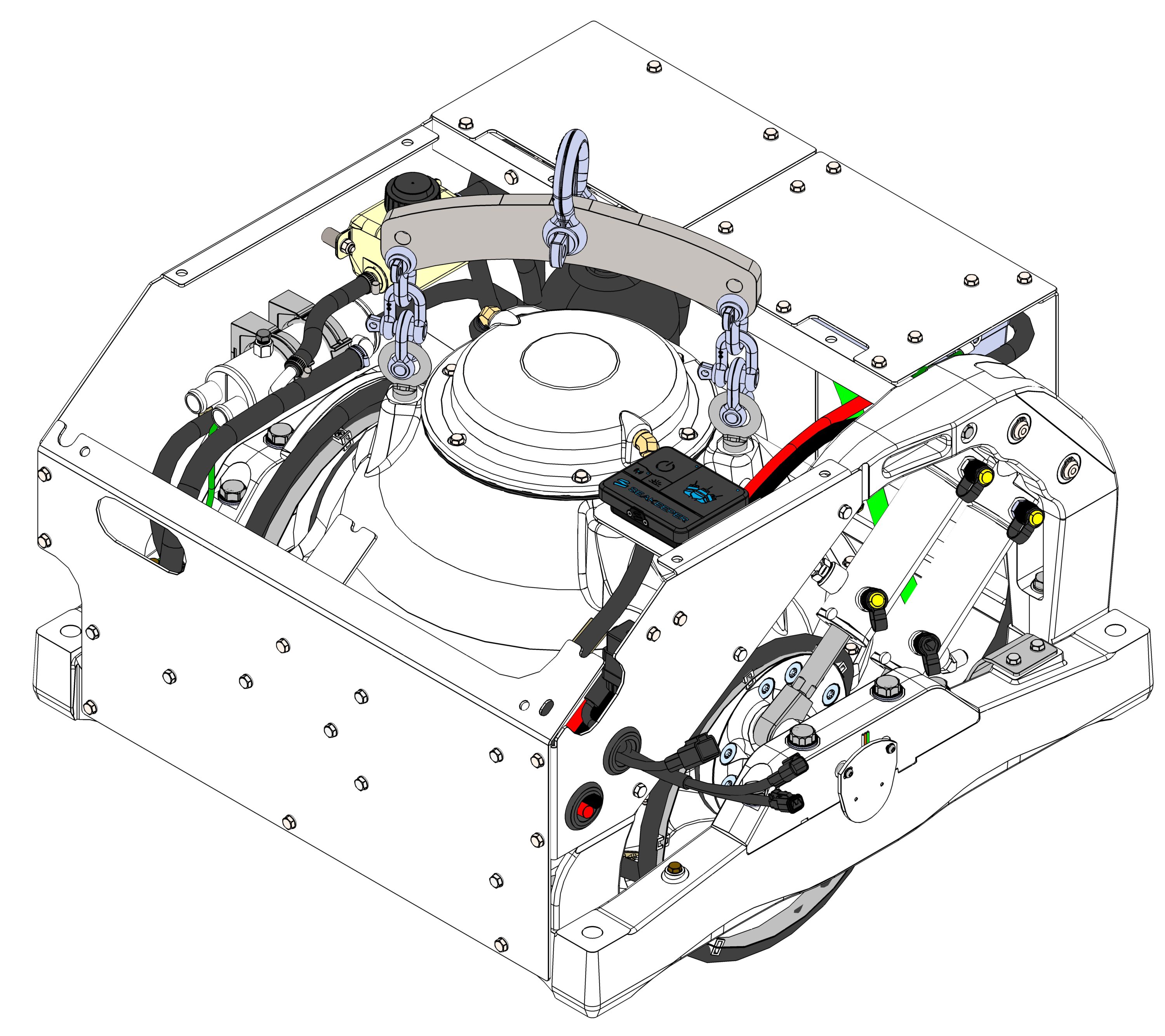
- The Seakeeper must only be lifted from the supplied lifting eyes (see Section: Transport and Unpacking).
- The Seakeeper flywheel is supported by precision bearings. While unpacking and lifting the Seakeeper assembly DO NOT drop or impart mechanical shock as damage tobearings could result.
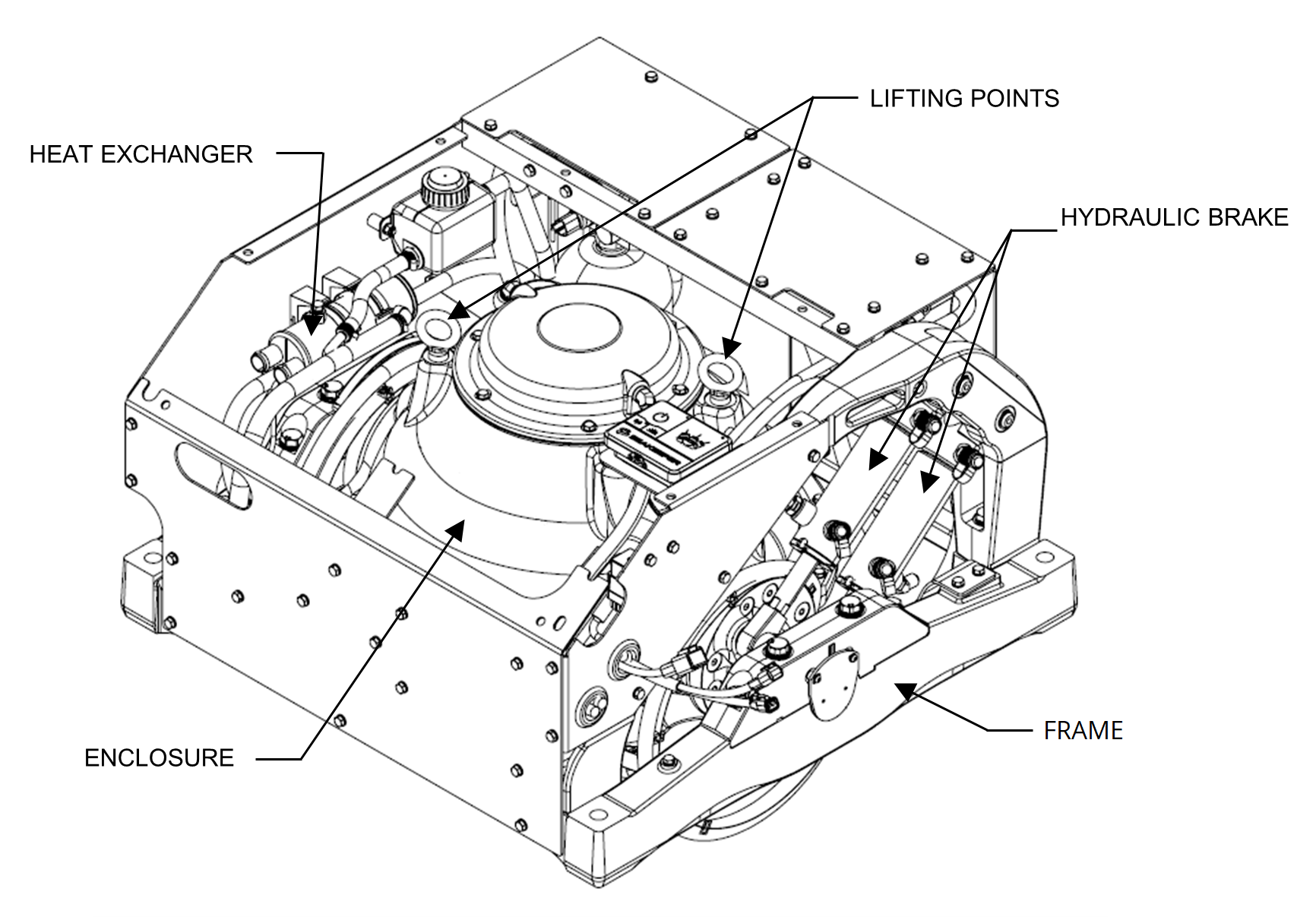
- While handling / installing the Seakeeper assembly, protect exposed hydraulic brake cylinder rods (see figure 1) from scratches or damage as this could lead to premature seal failure and oil leaks.
- While handling / installing the Seakeeper assembly, do not allow electrical fittings that exit bottom of the Seakeeper enclosure to come in contact with any surface or object as this could damage the fittings and potentially affect the vacuum integrity of the enclosure.
- Exercise care to protect the painted finish as damage to finish could lead to early appearance degradation of the installed Seakeeper.
1.1.1 Safety

There is a large torque about the gimbal axis when the Seakeeper is precessing. Seakeeper cover panels are provided to prevent personnel or equipment from contacting the Seakeeper while it is in operation. These covers should not be stepped on or have anything placed on top. The covers should always be in place during operation.
_________________________________________________________________________________________
If it is ever necessary to access the Seakeeper while the flywheel is spinning, the Seakeeper must be locked at the display to stop the Seakeeper from precessing.
_________________________________________________________________________________________
Stand clear of the Seakeeper and all moving components during operation.
_________________________________________________________________________________________
Unit may be started remotely. Assume it could move without warning.
_________________________________________________________________________________________
The following must be true before accessing the Seakeeper:
• Input power must be disconnected for at least 10 minutes
• Seakeeper must be locked
• Flywheel must be at zero speed
1.2 Transport and Unpacking
Reference Documents:
- 90394 – Seakeeper 3 Unpacking Instructions
- 90393 – Seakeeper 3 Packing list
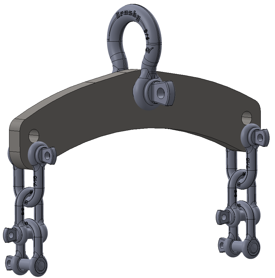
- 11766 – DC Lifting Bar Kit
1.2.1 Transport
Use a Seakeeper provided shipping crate for transport, P/N 11358. Overall dimensions of a fully packed crate are 37.5 L x 37.5 W x 31.3 H in. (0.95 L x 0.95 W x 0.80 H m) with a weight of728 lbs (330 kg).
- Seakeeper 3 crates can be stacked up to two (2) units high. Only like units should be stacked,
i.e., Seakeeper 3 on top of a Seakeeper 3. - Both Air and Ground transport are acceptable.
- Seakeeper shipping crates must be transported in environmental conditions between32°F and 140°F (0°C and 60°C).
1.2.2 Unpacking Crate
- Reference Seakeeper Drawing No. 90388, Seakeeper 3 Hardware Scope of Supply, for items that ship with the corresponding Seakeeper model.
- Remove covers, electrical components, display, cables, and misc. items and set aside.
- Remove packing materials that secure Seakeeper assembly inside the crate.
- Attach spreader bar (P/N 11766 available for purchase) to the two lifting eyes located on the top of the Seakeeper enclosure. Stay clear of any other parts on the Seakeeper .The Seakeeper 3 weighs 550 lbs (249 kg). See Figure 2 and 3 below.