Seakeeper 3 Installation Manual (90378-6); S/N 3-223-3836 to 3-231-4222
3.2 Electrical Equipment Power Connections
3.2.1 High Current 12 V Power Input
This Section outlines the requirements and process for connecting the Seakeeper 3 High Current 12 VDC power input.
3.2.1.1 High Current 12 VDC Power Source Requirements
| Source: | Battery Bank, 12 VDC, Marine Deep Cycle (Seakeeper recommends AGM batteries) |
| Voltage Range: | 11 – 15 VDC |
| Continuous Current: | 85 A (Max) |
| Overcurrent Protection: | 100 A (Customer Supplied) |
3.2.1.2 High Current 12 VDC Power Connection Instructions
- The 2 AWG conductors to connect the high current DC input power are supplied at13.12 ft (4 m). Approximately 3.28 ft (1 m) is routed within the gyro frame.
- The 2 AWG conductor length may be increased to a maximum of 29.53 ft (9 m), but changing from 2 AWG to larger wire size does not allow longer length. The length limit is required to limit the inductance from the high current conductors.
- Use the shortest length and most direct route to the battery bank as possible.
- Bind plus (B+, red) & minus (B-, black) conductors together throughout entire length and do not coil excess wire.
- Connect plus conductor (B+, red) through dedicated 100A over-current protection device (customer supplied) and a dedicated battery isolation switch (customer supplied) then directly to battery plus terminal or positive DC bus bar.
- Connect minus conductor (B-, black) directly to battery minus terminal.
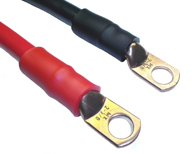
- If the 2 AWG high current 12 V power input conductors are shortened or lengthened, use heavy-duty eyelet (closed end) terminal such as Molex 19221-0235 and follow instructions outlined in the following steps.
- The bare wire strands should extend fully into the barrel of the heavy-duty eyelet and be crimped in two places if possible then sealed with double-wall heat shrink tubing. Crimp heavy-duty terminals with Quick Cable 4245 Crimp Tool, Molex19284-0034 Crimp Tool, or equivalent using manufacturer’s instructions.

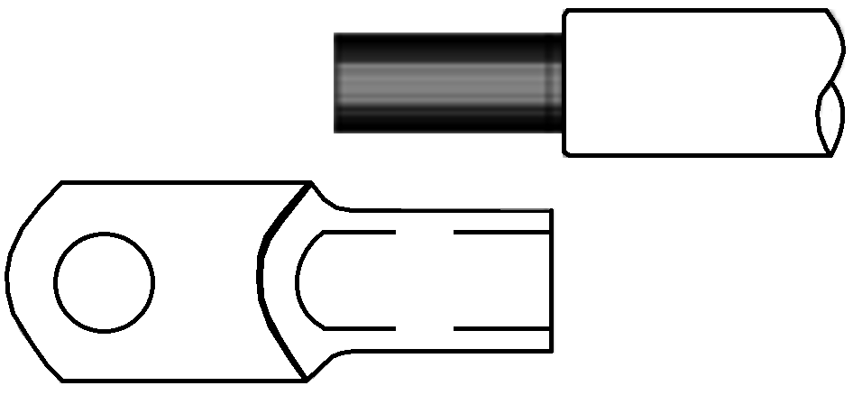
- Use heavy-duty eyelet (closed end) terminal such as Molex 19221 – Strip insulation from 2AWG conductor to the length of the terminal barrel approximately as shown.
- Insert stripped end of 2 AWG conductor fully into barrel of heavy-duty eyelet (closed end) terminal, approximately as shown.

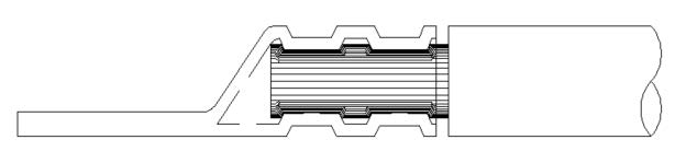
- Crimp with quick cable 4245 cub crimp tool or equivalent, double crimp, as shown.
- The resultant crimp(s) should fully enclose and confine the conductor strands from all sides and withstand an aggressive manual pull test.
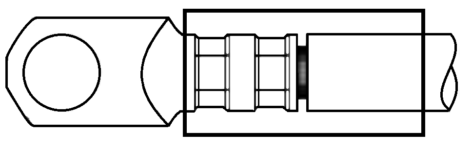
- Install approximately 1.5 in. (38 mm) of double wall (adhesive lined) heat shrink tubing over both the terminal barrel and the conductor insulation. Heat shrink in place until tubing conforms to barrel and conductor shape and adhesive seals the junction (See Figure 2).
3.2.2 Low Current 12 V Power Input
3.2.2.1 Low Current 12 VDC Power Source Requirements
| Source: | Battery Bank, 12 VDC, Marine Deep Cycle (Seakeeper recommends AGM batteries) |
| Voltage Range: | 11 – 15 VDC |
| Continuous Current: | 9 A |
| Overcurrent Protection: | 15 A (Customer Supplied) |
3.2.2.2 Low Current 12 VDC Power Connection Instructions

Reversing polarity on the DC power input to the
Seakeeper can result in damaging the electronics in the control system.
- Install Seakeeper-provided Low Current DC Power Input Cable, (P/N 20248), as Cable 7to battery bank, per Drawing Number 90377.
- Connect plus conductor (B+, red) through dedicated over-current protection device(customer supplied) and a dedicated Seakeeper isolation switch (customer supplied).The High Current, 2AWG, B+ conductor (red), is capable of carrying the current for both the High Current, Low Current, and Seawater Pump from the 12VDC power supply to the dedicated battery isolation switch.
- Connect minus conductor (B-, black) directly to battery minus terminal or negative DCbus bar.
- Before connecting Cable 7 to Seakeeper, check for proper voltage and polarity with a DC multimeter using Figure 3 below.
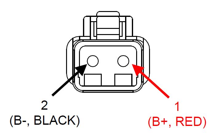
- Connect Cable 7 to Low Current 12 VDC power input connector on the Seakeeper, DEUTSCH DTP04-2P connector.
3.2.3 Seawater Pump Connection Instructions
3.2.3.1 DC Seawater Pump 12 VDC Power Source Requirements:
| Source: | 12 VDC from the Seakeeper |
| Voltage Range: | 11 – 15 VDC |
| Current Rating: | On Demand, typically ~ 10 A |
| Overcurrent Protection | Per pump specification, max 15 A |
3.2.3.2 Seawater Pump 12 VDC Power Input Connection Instructions
- Install Cable 8 (P/N: 30327) to Seakeeper 3 “SW Pump DC In” (as shown in Drawing No. 90377) with overcurrent protection corresponding to seawater pump selected.
- Connect the 16AWG plus conductor (red) through dedicated overcurrent protection device (customer-supplied), maximum of 15A, to dedicated battery isolation switch.
- Cable 1, 2 AWG B+ conductor (red), is capable of carrying the current for both the High Current, Low Current, and Seawater Pump from the 12VDC power supply to the battery isolation switch.
- Connect the 16 AWG minus conductor (black) directly to battery minus terminal or DC main negative bus bar.
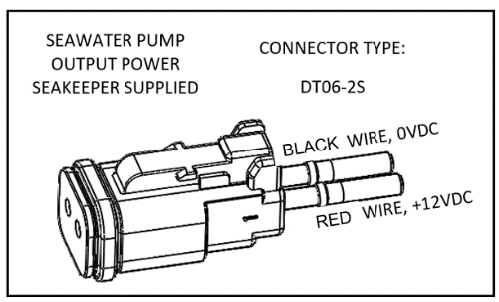
- Before connecting Cable 8 to Seakeeper, check for proper voltage and polarity with a DC multimeter using Figure 4 below.
- Connect Cable 8 to Seawater Pump 12 VDC In connector on the Seakeeper, DEUTSCHDT04-2P connector.
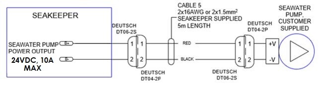
3.2.3.3 Seawater Pump 12 VDC Power Output Connection Instructions
- Connect Cable 5 to the Seakeeper 3 “SW Pump 12VDC Out” for DC power output to the seawater pump.
- Cable 5 is a 2 x 16AWG cable, 16 ft (5m) length, with a size 16 female Deutsch plug.
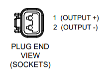
- Pumps rated at 12 VDC, 15 A maximum, customer-supplied, must be configured with a Deutsch DT series, 2-pin receptacle to mate with the connector shown in Figure 5.
- Cable 5 must be routed and installed in the vessel from the Seakeeper 3 “SW Pump12VDC Out” Deutsch connector (pins end) to the DC seawater pump cable Deutsch connector (socket end).
- Connect Cable 5 plug end (socket end) to the customer-supplied receptacle end (pin end). The recommended wiring is shown in Figure 6.