Seakeeper 3 Installation Manual (90378-6); S/N 3-223-3836 to 3-231-4222
2.0 Mechanical Installation
2.1 Mechanical Installation Introduction
The Seakeeper 3 can produce forces of up to 1,934 lbs (8.60 kN) in the vertical direction,1,224 lbs (5.44 kN) in the longitudinal direction, and 150 lbs (0.67 kN) in the lateral direction at each of the four mounts. These forces should be considered to be acting simultaneously, fully reversing, and will repeat an infinite number of times. Careful consideration should begiven to foundation design to ensure it is capable of transferring these loads into the hull. These loads do NOT include vessel motion accelerations, such as vertical slam loads which can be significant for high speed vessels. The responsible party for designing the supporting structure (boat builder, installer, or hired sub-contractor) must accommodate the above forces plus a reasonable factor of safety. Seakeeper recommends a minimum safety factor of 3.0 (yielding a Safety Margin of 2.0).
It is assumed that the installer is familiar with mounting using mechanical fasteners to marine structures and has performed structural analysis to assure the structure to which the Seakeeper mounts can properly transfer the loads the Seakeeper creates into the hull structure. If the installer has any doubt about the ability of the structure to transfer the loads to the hull then a licensed naval architect or marine engineer should be contacted to do a structural analysis.
The installer should review the following list of reference drawings to ensure the installation procedure and structural requirements are fully understood.
Reference Documents:
2.2 Selection of Installation Location

Seakeeper can only assess installation location regarding its impact on Seakeeper operation and serviceability. Seakeeper cannot determine how the installation location will affect the vessel static or directional stability other than cyclic roll reduction. The Installer is responsible for considering the Seakeeper ’s effect on the CG location, trim, overall stability, and performance of the vessel.
Selection of mounting location of the Seakeeper should consider the following desirable features:
- Provide adequate clearance for all recommended scheduled maintenance and any repairs that may be necessary, as shown in Figure 1 and installation drawings.
- The Seakeeper should be installed in a dry space to minimize effects of corrosion.
- Installed near the vessel’s longitudinal center of gravity (LCG) to minimize effects on trim and performance in various loading conditions.
- Overhead access or sufficient clearance for removal / re-installation of the Seakeeper for overhaul in future years.
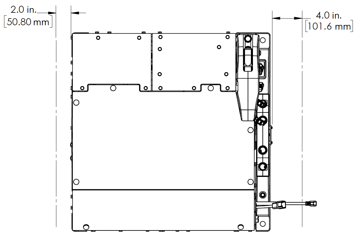
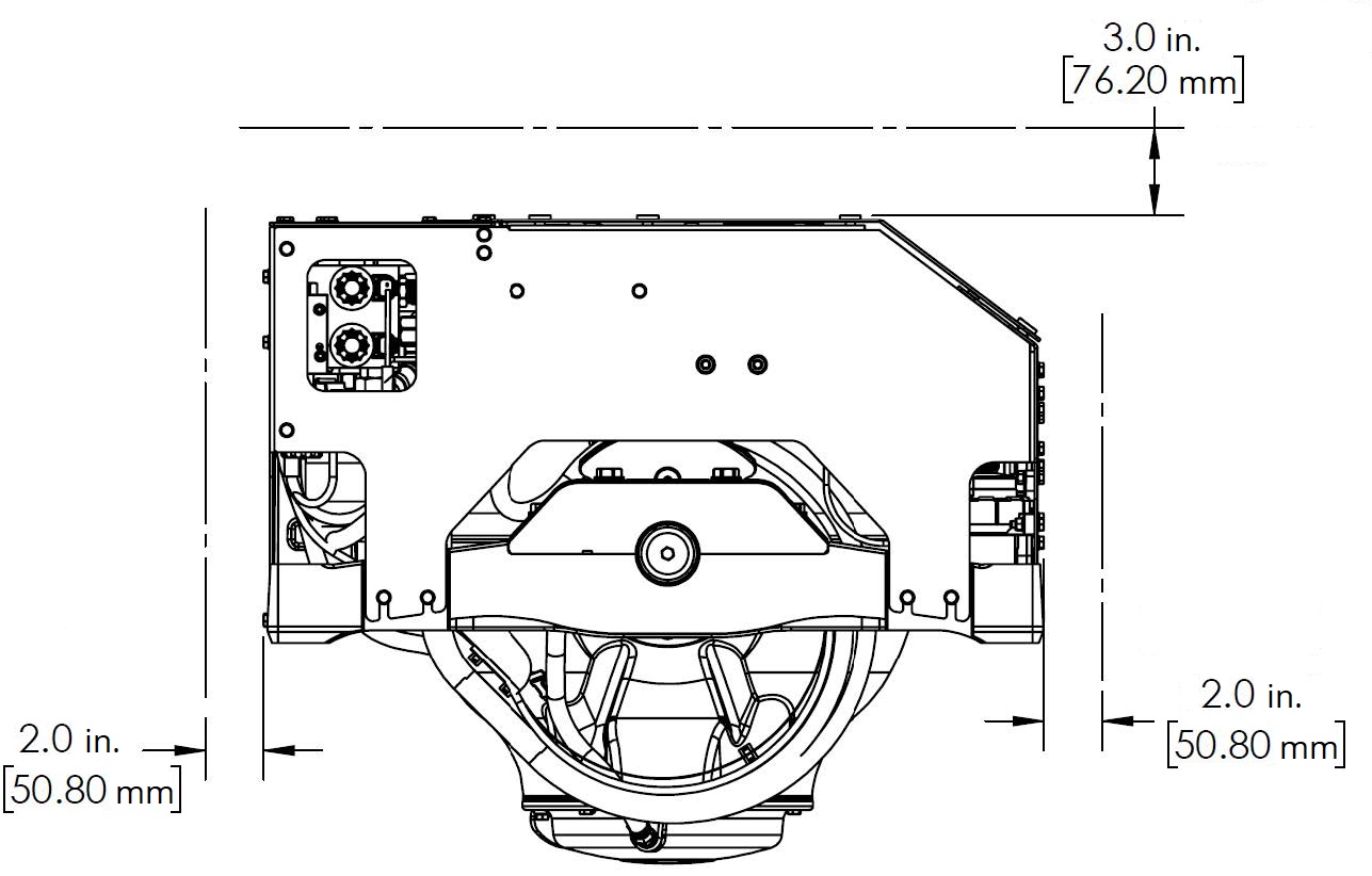
Refer to Figure 2 for recommended clearances to transverse or longitudinal beams. Clearances aft of the
Seakeeper are shown to provide access for regular scheduled maintenance.


2.2.1 Noise / Soundproofing
Seakeeper noise has been measured under steady state conditions (no wave load) in Seakeeper‘s Engineering Lab and in our Factory Demo Boat. The steady state noise is <72dBC at 1 meter. As the frequencies emitting the highest sound pressures are low (like other marine machinery), it is recommended that the Seakeeper be installed in an enclosed space such as a leaning post / seat, bilge, center console, or machinery space. This space can be treated with soundproofing if desired and does not require ventilation for Seakeeper operation.
2.3 Bolt-In Installation
2.3.1 Preparation of Boat Structure
The Seakeeper Drawing No. 90591, Seakeeper 3 Generic Installation Guide shows various structural arrangements to support the installation of the Seakeeper. The Generic Installation Guide offers above and below deck installation arrangements with fiber-reinforced plastic (FRP) and aluminum structures, which should provide solutions for most vessels. The Seakeeper 3 is affixed to the hull structure via four bolts in the
Seakeeper 3 frame. Depending on the structure to which the Seakeeper is fastened, blind threaded holes or through-bolting can be utilized.
Refer to Seakeeper Drawing No. 90374, Seakeeper 3 Bolt in Installation Guide. Important dimensional and load information is given in this drawing that will impact the design details of the structure that will receive the Seakeeper. It is assumed that a proper structural analysis has been performed for the hull structure to which the Seakeeper will be fastened to ensure proper strength margins for the loads the Seakeeper will create during operation.
The hull structure supporting the Seakeeper should be installed so the Seakeeper is parallel to the waterline in the transverse direction and within 1 degree longitudinally.
In addition, the four areas on top of the structure on which the Seakeeper 3 frame and isolation gaskets will rest, need to be co-planar within .06 in. (1.5 mm) to minimize potential distortion of Seakeeper support frame when installed. The isolation gaskets are only used when the Seakeeper 3 is mounted to a dissimilar metal structure.
Seakeeper offers an optional installation template kit, P/N 90362, which contains four plates that mimic the mating surfaces of the four feet located on the Seakeeper ’s foundation. These plates have 4 holes located at the same centers as the mounting holes on the Seakeeper 3.The fixture locates the hole patterns at the proper spacing both in the forward-aft direction and the port-starboard direction. See Figure 5 below. Once assembled, the fixture can be used to check clearances and alignment of the hull structure.
Note: Do NOT use the installation fixture to establish the Seakeeper envelope dimensions. Refer to Drawing No. 90374 – Seakeeper 3 Bolt-In Installation Details, for envelope dimensions. A 3-D model of the Seakeeper is available on the Seakeeper Dealer Access website (www.seakeeper.com) to aid in designing the Seakeeper foundation and the space around the Seakeeper
NOTE: MAKE SURE NO OBSTRUCTIONS FROM THE HULL STRUCTURE CAN BE SEEN WITHINTHE INSIDE OF THE INSTALLATION TEMPLATE KIT (INSIDE THE MARKED RED LINES) AS SEEN IN FIGURE 4. REFERENCE SEAKEEPER DRAWING NO. 90374 – SEAKEEPER 3 BOLT-ININSTALLATION DETAILS
.

CAUTION: Tight clearances from cable guide bands to hull structure.
See above figure for dimensions and reference Seakeeper Drawing No. 90374,
Seakeeper 3 Bolt-In Installation Details, for complete Seakeeper 3 envelope.
2.3.2 Transfer of Holes to Boat Structure
- Lower assembled fixture onto hull structure.
- The four areas where the feet of the Seakeeper will rest should be coplanar to within .06 in. (1.5 mm). See Figure 5.
- Align fixture (P/N 90362) in desired location and transfer holes from fixture plate to the hull structure.
Note: Holes in fixture plate are ø0.64 in. (16.26 mm).
2.3.2.1 Blind Hole Installation
- Remove Template Fixture and drill four (4) 0.65 in. (16.5 mm) holes perpendicular to the vessel structure to a minimum depth of 0.94 in. (24 mm). Take special care to drill perpendicular to mounting surface. A drill guide is recommended. Remove any impeding obstructions.
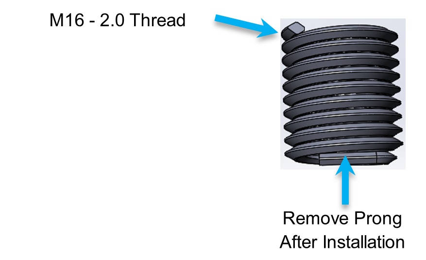
- Tap drilled holes for helical thread inserts per documentation accompanying helical threaded inserts. (Tap will be included in thread insert kit.)
- Install four (4) M16-2.0 X 24 mm threaded inserts into holes in hull structure at drilled and tapped locations using threaded insert manufacturer provided installation tool.
- Remove threaded insert prong / tang after threaded inserts are installed.
2.3.2.2 Through-Hole Installation
- Remove Template Fixture and drill four (4) 0.67 in. (17 mm) ø holes perpendicular to the vessel structure.
NOTE: Take special care to drill perpendicular to mounting surface. A drill guide is recommended.
2.3.3 Installation of Seakeeper
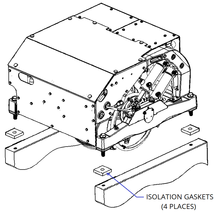
- Lower Seakeeper into position onto the hull foundation beams and align over drilled holes. Apply a small bead of marine sealant (e.g., SILI-THANE 803 or equivalent)between mating surfaces of Seakeeper frame and hull structure to prevent moisture wicking into bolt holes.
- For dissimilar metal foundations locate and position 4 isolation gaskets onto foundation beams and apply a small bead of marine sealant (e.g., SILI-THANE 803or equivalent) between both mating surfaces of each isolation gasket where it contacts the beam and the Seakeeper (See Figure 6).
- Install mounting bolts:
- For Blind Hole Installations, install the Seakeeper supplied Grade 10.9, M16-2.0 x110 mm fasteners or alternative Grade 10.9, M16-2.0 bolts to maintain a minimum thread engagement of .94 in (24 mm). If Seakeeper supplied bolts do not achieve the minimum thread engagement because of the lamination thickness or structure, longer bolts of the same specification (M16-2.0, Grade10.9) should be sourced. If tapping directly into a metal frame shorter bolts maybe required. Apply a moderate coat of marine anti-seize (e.g., SAF-T-EZE nickel grade anti-seize, SBT-4N or equivalent) to the threads of each bolt and include a small bead of marine grade sealant (e.g., SILI-THANE 803 or equivalent) under each bolt head and washer before installation. See Figure 7 below.
- For Through-Bolt installation install the Seakeeper optional Thru-Bolt Kit (P/N90641) Grade 10.9, M16-2.0 x 120 mm fasteners with a minimum of 2 threads passing through the nut If Seakeeper supplied bolts do not pass entirely through the Extra Wide / Heavy Hex Nut because of the frame thickness, longer bolts of the same specification (M16-2.0, Grade 10.9) should be sourced. Apply a moderate coat of marine anti-seize (e.g., SAF-T-EZE nickel grade anti-seize, SBT-4Nor equivalent) to the threads of each bolt and include a small bead of marine grade sealant (e.g., SILI-THANE 803 or equivalent) under each bolt head and washer before installation. See Figure 8 below.

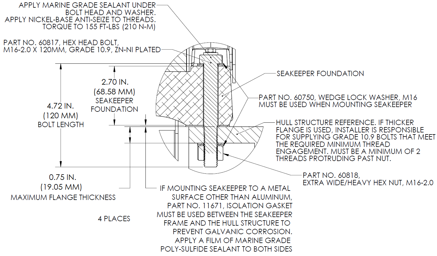
- Torque all fasteners to 155 ft-lbs (210 Nm).
- New bolts matching the Seakeeper specification must be used for each installation.
- Proceed to electrical and cooling portion of the installation.