Seakeeper 2 Installation Manual (90488-3); S/N 2-203-0400 to 2-232-1563
Seakeeper 2 Installation Manual (90488-3); S/N 2-203-0400 to 2-232-1563
Introduction
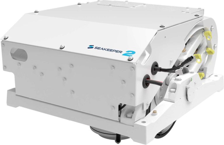
Seakeeper 2
Installation Manual
90488, Rev 3
This document is intended to give details and guidance to a boat builder or equipment installer to install the Seakeeper 2, Serial numbers 2-203-0400 to 2-232-1563.
Mechanical Installation
Mechanical Installation Introduction
The Seakeeper 2 is capable of producing loads up to 1,459 lbs (6.49 kN) at each of the four mounts and careful consideration should be given to foundation design to insure it is capable of transferring these loads into the hull. These loads do NOT include vessel motion accelerations, such as vertical slam loads which can be high for higher speed vessels. Seakeeper suggests a safety factor of 3.0 (yielding a safety margin of 2.0).
There are two methods of installing the Seakeeper 2:
1. Longitudinal Bolt-In Installation
2. Transverse Bolt-In Installation
It is assumed that the installer is familiar with mounting using mechanical fasteners to marine structures and has performed structural analysis to assure the structure to which the Seakeeper mounts can properly transfer the loads the Seakeeper creates into the hull structure. If the installer has any doubt about the ability of the structure to transfer the loads to the hull then the installer should contact a licensed naval architect or marine engineer to do a structural analysis.
The installer should review the following list of reference drawings to ensure the installation procedure is fully understood.
Reference Documents & Drawings:
Link to Seakeeper 2 Reference Documents
- 90469 – Seakeeper 2 Hardware Scope of Supply
- 90487 – Seakeeper 2 Installation Details – Bolt in Method
- 90490 – Seakeeper 2 Cooling Water Schematic
- 90473 – Seakeeper 2 Installation Template Kit
- 90470 – Seakeeper 2 Cable Block Diagram
Precautions
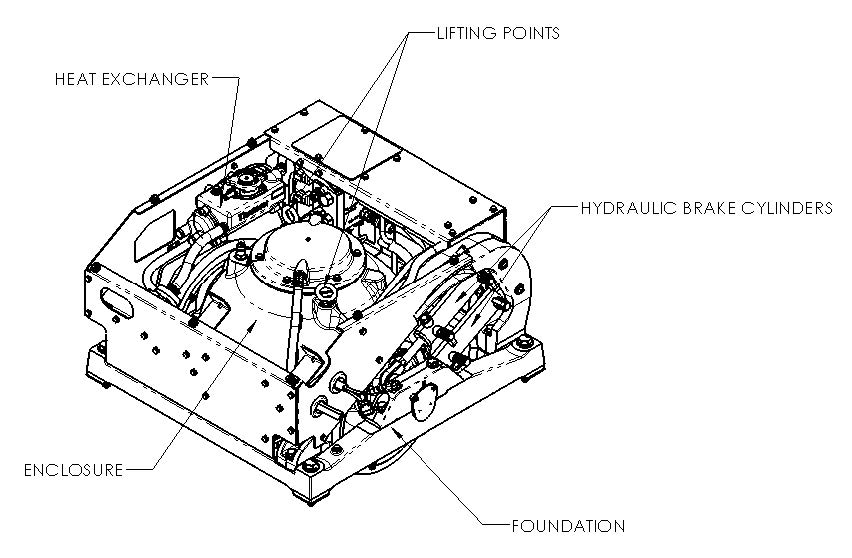
- The Seakeeper must only be lifted from the supplied lifting eyes (see Section: Transport and Unpacking).
- The Seakeeper flywheel is supported by precision bearings. Make certain while unpacking and lifting the Seakeeper assembly to NOT drop or impart mechanical shock as damage to bearings could result.
- While handling / installing the Seakeeper assembly, protect exposed hydraulic brake cylinder rods (See Figure 1) from scratches or damage as this could lead to premature seal failure and oil leaks.
- While handling / installing the Seakeeper assembly, do not allow electrical fittings that exit bottom of the Seakeeper enclosure to come in contact with any surface or object as this could damage the fittings and potentially affect the vacuum integrity of the enclosure.
- Exercise care to protect the painted finish as damage to finish could lead to early appearance degradation of the installed Seakeeper.
Selection of Installation Location
Selection of mounting location of the Seakeeper should consider the following desirable features:
The Seakeeper should be installed aft of amidships to minimize high acceleration loadings due to hull/wave impacts during operation at high speed or in large waves. If the only possible Seakeeper location is forward of amidships then the installer should have Seakeeper review the installation location prior to finalizing the design.
- Top down access or sufficient clearance for removal / re-installation of the Seakeeper for overhaul in future years.
- The Seakeeper should be installed in a dry space to minimize effects of corrosion.
- Clearance for all recommended scheduled maintenance and any repairs that may be necessary (see Figure 2).
VIEWS SHOWING RECOMMENDED CLEARANCES AROUND THE SEAKEEPER FOR USE OF HANDTOOLS, EASE OF MAINTENANCE, INSTALLATION, AND PROPER OPERATION.
Figure 2 – Seakeeper 2 Installed Clearance Considerations
Refer to Figure 3 for recommended clearances to transverse or longitudinal beams. Clearances aft of the Seakeeper are shown to provide access for regular scheduled maintenance.
Safety

There is a large torque about the gimbal axis when the Seakeeper is precessing. Seakeeper cover panels are provided to prevent personnel or equipment from contacting the Seakeeper while it is in operation. These covers should not be stepped on or have anything placed on top. The covers should always be in place during operation. If it is ever necessary to access the Seakeeper while the flywheel is spinning, the Seakeeper must be locked at the display to stop the Seakeeper from precessing. Seakeeper regular scheduled maintenance should not be attempted unless the Seakeeper is locked and the flywheel has stopped spinning.
The Seakeeper should be treated with the same respect one gives a high speed rotating propeller shaft or engine shaft.
Noise/Soundproofing
Seakeeper noise has been measured under steady state conditions (no wave load) in Seakeeper‘s Engineering Lab and in our Factory Demo Boat. The steady state noise at 1 meter is typically in the range of 64-68 dBC un-weighted. As the frequencies emitting the highest sound pressures are low (like other marine machinery), it is recommended that the Seakeeper be installed in a machinery space that is already treated with soundproofing.
Transport and Unpacking
Transport
- Use a Seakeeper provided shipping crate for transport, P/N 11851. Overall dimensions of a fully packed crate are 36.25 L x 35.75 W x 38 H in. (0.92 L x 0.91 W x 0.97 H m) with a weight of 482 lbs (219 kg).
- Do not stack Seakeeper shipping crates.
- Both Air and Ground transport are acceptable.
- Seakeeper shipping crates must be transported in environmental conditions between -4°F and 140°F (-20°C and 60°C).
Unpacking Crate
- Reference Seakeeper Drawing No. 90469 – Seakeeper 2 Hardware Scope of Supply, for items that ship with the corresponding Seakeeper model.
- Remove covers, electrical components, display, cables, and misc. items and set aside.
- Remove packing materials that secure Seakeeper assembly inside the crate.
- Attach spreader bar (P/N 11766; available for purchase) to the two lifting eyes located on the top of the Seakeeper enclosure. Stay clear of any other parts on the Seakeeper. The Seakeeper 2 weighs 414 lbs (188 kg). See Figure 4 below.

Longitudinal Bolt-In Installation
Check and Preparation of Hull Structure
The Seakeeper 2 can be affixed to the hull structure using two methods 1) Longitudinal Beam Bolt-In installation or 2) Transverse Beam Bolt-In installation. Neither option affects the operation of the Seakeeper. However, one option might ease the installation process or allow for a larger service envelope. Depending on the structure to which the Seakeeper is fastened, blind threaded holes or thru-bolting can be utilized.
Refer to Seakeeper Drawing No. 90487 – Seakeeper 2 Installation Details – Bolt in Method. Important dimensional and load information is given in this drawing that will impact the design details of the structure that will receive the Seakeeper. It is assumed that a proper structural analysis has been performed for the hull structure to which the Seakeeper will be fastened to ensure proper strength margins for the loads the Seakeeper will create during operation.
The hull structure supporting the Seakeeper should be installed so the Seakeeper is parallel to the waterline. In addition, the four areas on top of the beams on which the feet of the Seakeeper foundation and isolation gaskets will rest, need to be co-planar within .06 in. (1.5 mm) to minimize potential distortion of Seakeeper support frame when installed. The isolation gaskets are only used on dissimilar metal to metal contacts.
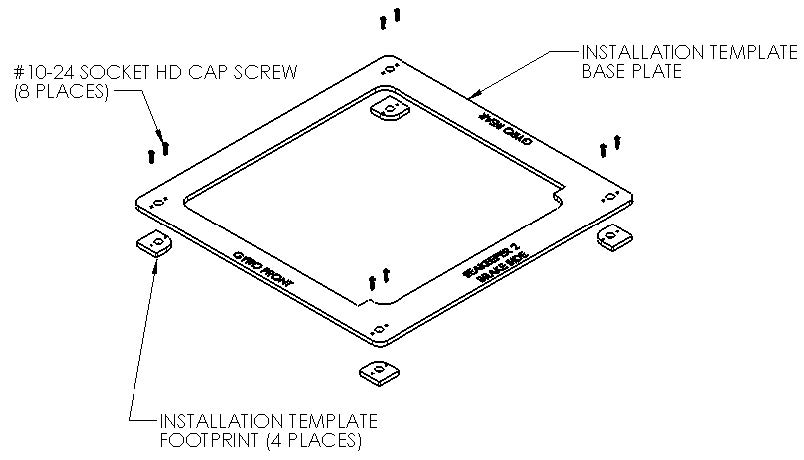
Seakeeper offers an optional installation template kit, P/N 90473, which contains four plates that mimic the mating surfaces of the four feet located on the Seakeeper’s foundation. These plates have 4 holes located at the same centers as the mounting holes on the Seakeeper. The fixture locates the hole patterns at the proper spacing both in the forward-aft direction and the port-starboard direction. See Figure 5 below. Once assembled, the fixture can be used to check clearances and alignment of the hull structure.
Note: Do NOT use the installation fixture to establish the Seakeeper envelope dimensions. Refer to Drawing No. 90487 – Seakeeper 2 Bolt-In Installation Details, for envelope dimensions. A 3-D model of the Seakeeper is available on the Seakeeper website (www.seakeeper.com) to aid in designing the Seakeeper foundation and the space around the Seakeeper.
NOTE: MAKE SURE NO OBSTRUCTIONS FROM THE HULL STRUCTURE CAN BE SEEN WITHIN THE INSIDE OF THE INSTALLATION TEMPLATE KIT (INSIDE THE MARKED RED LINES). REFERENCE SEAKEEPER DRAWING NO. 90487 – SEAKEEPER 2 BOLT-IN INSTALLATION DETAILS.
CAUTION: Tight clearances from cable guide bands to hull structure. See above figure for dimensions and reference Seakeeper Drawing No. 90487 – Seakeeper 2 Bolt-In Installation Details, for complete Seakeeper 2 envelope.
Transfer of Holes to Boat Structure
- Lower assembled fixture onto hull structure.
- The four areas where the feet of the Seakeeper will rest should be coplanar to within .06 in. (1.5 mm). See Figure 7.
- Align fixture in desired location and transfer holes from fixture plate to the hull structure. Note that holes in fixture plate are ø0.60 in. (15.138 mm).
- Remove fixture and drill and tap M14X2.0 Helicoil threaded insert holes in hull structure at marked locations to mate with holes in the Seakeeper foundation. Take special care to drill perpendicular to mounting surface. A drill guide is recommended. Remove any impeding obstructions.
Installation of Seakeeper
- Locate and position 4 isolation gaskets onto foundation beams (for metal to metal contacts only). NOTE: Sealant or caulk is recommended to be applied. Apply a small bead (approximately 4 mm wide) of sealant (silicone or caulk) between both mating surfaces of each isolation gasket where it contacts the beam and the Seakeeper. This will prevent water from wicking between the parts and setting up corrosion. Check isolation gasket alignment by test fitting bolts without any obstructions.
- Lower Seakeeper into position onto the hull foundation beams and align over drilled holes.
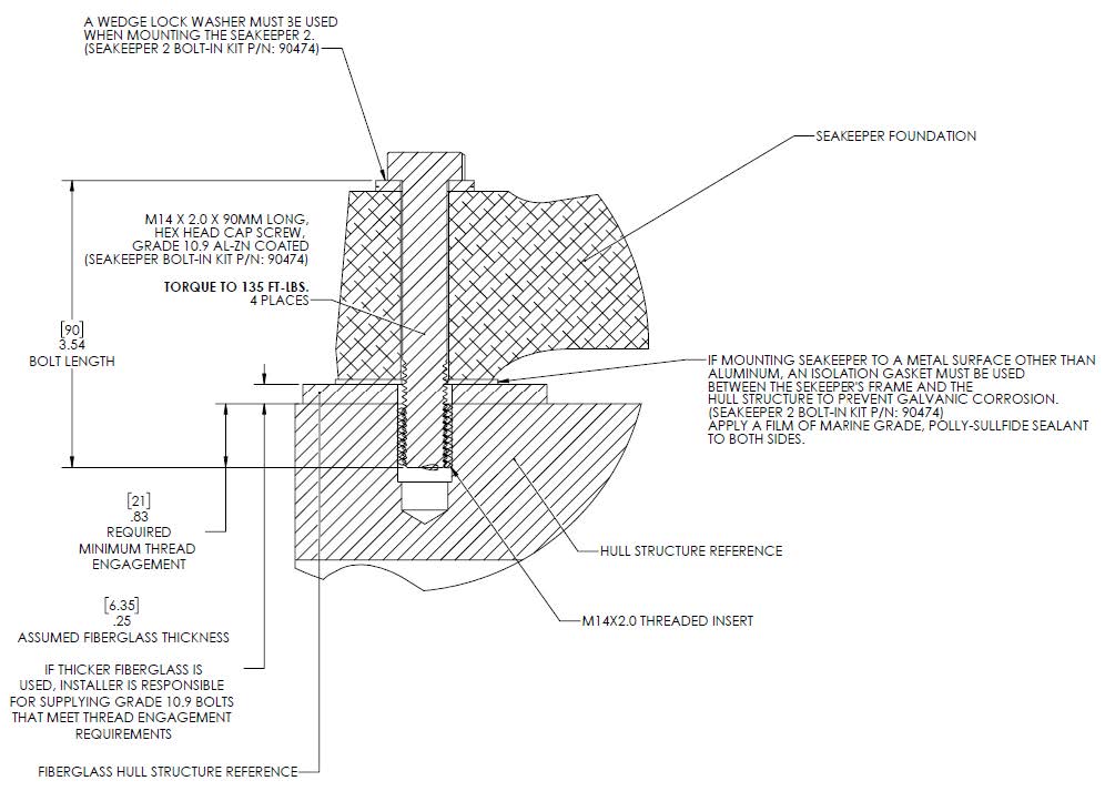
- Install Seakeeper supplied M14 fasteners Or Grade 10.9, M14-2.0 bolts to maintain a minimum thread engagement of .83 in. (21 mm) – apply a moderate coat of removable thread locker to the threads of each bolt and include a small bead of sealant under each washer before installation.
- Torque all fasteners to 135 ft-lbs (183 N-m). New Seakeeper supplied bolts must be used for each installation and reinstallation.
- Proceed to electrical and cooling portion of the installation.

Transverse Bolt-In Installation
Check and Preparation of Hull Structure
The Seakeeper 2 can be affixed to the hull structure using two methods 1) Longitudinal Beam Bolt-In installation or 2) Transverse Beam Bolt-In installation. Neither option affects the operation of the Seakeeper. However, one option might ease the installation process or allow for a larger service envelope. Depending on the structure to which the Seakeeper is fastened, blind threaded holes or thru-bolting can be utilized.
Refer to Seakeeper Drawing No. 90487 – Seakeeper 2 Bolt-In Installation Details. Important dimensional and load information is given in this drawing that will impact the design details of the structure that will receive the Seakeeper. It is assumed that a proper structural analysis has been performed for the hull structure to which the Seakeeper will be fastened to ensure proper strength margins for the loads the Seakeeper will create during operation.
The hull structure supporting the Seakeeper should be installed so the Seakeeper is parallel to the waterline. In addition, the four areas on top of the beams on which the feet of the Seakeeper foundation and isolation gaskets will rest, need to be co-planar within .06 in. (1.5 mm) to minimize potential distortion of Seakeeper support frame when installed. The isolation gaskets are only used on dissimilar metal to metal contacts.
Seakeeper offers an optional installation template kit, P/N 90473, which contains four plates that mimic the mating surfaces of the four feet located on the Seakeeper’s foundation. These plates have 4 holes located at the same centers as the mounting holes on the Seakeeper. The fixture locates the hole patterns at the proper spacing both in the forward-aft direction and the port-starboard direction. See Figure 10 below. Once assembled, the fixture can be used to check clearances and alignment of the hull structure.
Note: Do NOT use the installation fixture to establish the Seakeeper envelope dimensions. Refer to Drawing No. 90487 – Seakeeper 2 Bolt-In Installation Details, for envelope dimensions. A 3-D model of the Seakeeper is available on the Seakeeper website (www.seakeeper.com) to aid in designing the Seakeeper foundation and the space around the Seakeeper.
NOTE: MAKE SURE NO OBSTRUCTIONS FROM THE HULL STRUCTURE CAN BE SEEN WITHIN THE INSIDE OF THE INSTALLATION TEMPLATE KIT (INSIDE THE MARKED RED LINES). REFERENCE SEAKEEPER DRAWING NO. 90487 – SEAKEEPER 2 BOLT-IN INSTALLATION DETAILS.
CAUTION: Tight clearances from cable guide bands to hull structure. See above figure for dimensions and reference Seakeeper Drawing No. 90487 – Seakeeper 2 Bolt-In Installation Details, for complete Seakeeper 2 envelope.
Transfer of Holes to Boat Structure
- Lower assembled fixture onto hull structure.
- The four areas where the feet of the Seakeeper will rest should be coplanar to within .06 in. (1.5 mm). See Figure 12.
- Align fixture in desired location and transfer holes from fixture plate to the hull structure. Note that holes in fixture plate are ø0.60 in. (15.138 mm).
- Remove fixture and drill and tap M14X2.0 Helicoil threaded insert holes in hull structure at marked locations to mate with holes in the Seakeeper foundation. Take special care to drill perpendicular to mounting surface. A drill guide is recommended. Remove any impeding obstructions.
Installation of Seakeeper
- Locate and position 4 isolation gaskets onto foundation beams (for metal to metal contacts only). NOTE: Sealant or caulk is recommended to be applied. Apply a small bead (approximately 4 mm wide) of sealant (silicone or caulk) between both mating surfaces of each isolation gasket where it contacts the beam and the Seakeeper. This will prevent water from wicking between the parts and setting up corrosion. Check isolation gasket alignment by test fitting bolts without any obstructions.
- Lower Seakeeper into position onto the hull foundation beams and align over drilled holes.
- Install Seakeeper supplied M14 fasteners Or Grade 10.9, M14-2.0 bolts to maintain a minimum thread engagement of .83 in. (21 mm) – apply a moderate coat of removable thread locker to the threads of each bolt and include a small bead of sealant under each washer before installation.
- Torque all fasteners to 135 ft-lbs (183 N-m). New, Seakeeper supplied bolts must be used for each installation and reinstallation.
- Proceed to electrical and cooling portion of the installation.
Removal and Disposal
Removal
This section details basic instructions for removal of a Seakeeper 2 from a boat. The overall basic instructions are to reverse the installation instructions:
- Disconnect seawater pump from heat exchanger and power connector on wiring harness.
- Drain heat exchanger of all seawater.
- Disconnect both Seakeeper input power cables.
- Remove all installation fasteners.
- Remove the Seakeeper unit using a spreader bar.
Disposal
DO NOT disassemble the Seakeeper to a greater degree than necessary for removal from the boat. DO NOT dispose of a Seakeeper unit in a landfill. The unit must be shipped back to Seakeeper.
Electrical Installation
Electrical Installation Introduction
This section for electrical installation explains how to mount the electrical equipment and how to connect the electrical cables.
Reference Documents & Drawings:
Link to Seakeeper 2 Reference Documents
- 90469 – Seakeeper 2 Hardware Scope of Supply
- 90470 – Seakeeper 2 Cable Block Diagram
- 90438 – 5″ Operator Display Envelope and Mounting Details
- Tb 90191 Seawater Cooling Pump Recommendations
- TB 90478 – Garmin and Seakeeper Compatibility
- TB 90479 – Raymarine and Seakeeper Compatibility
- TB 90480 – Simrad and Seakeeper Compatibility


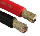
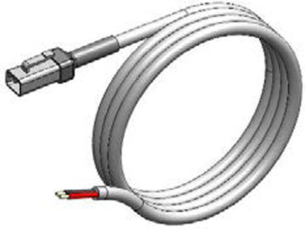
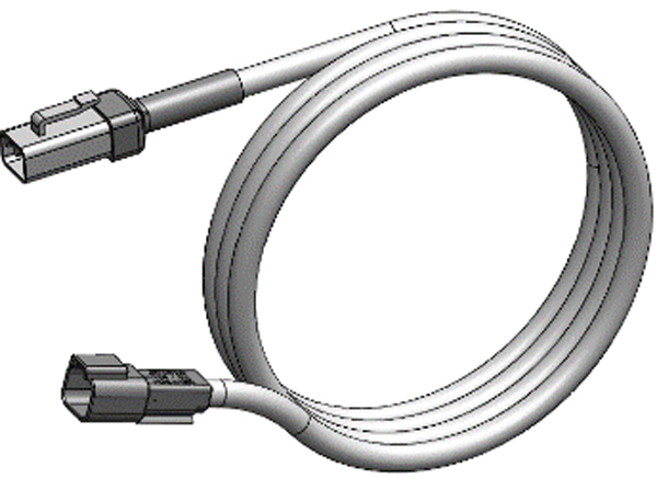

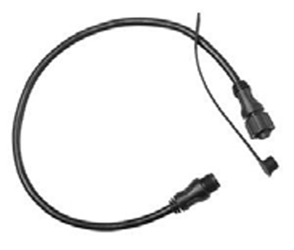
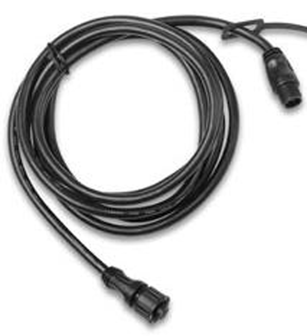
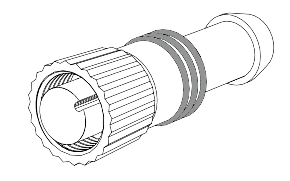
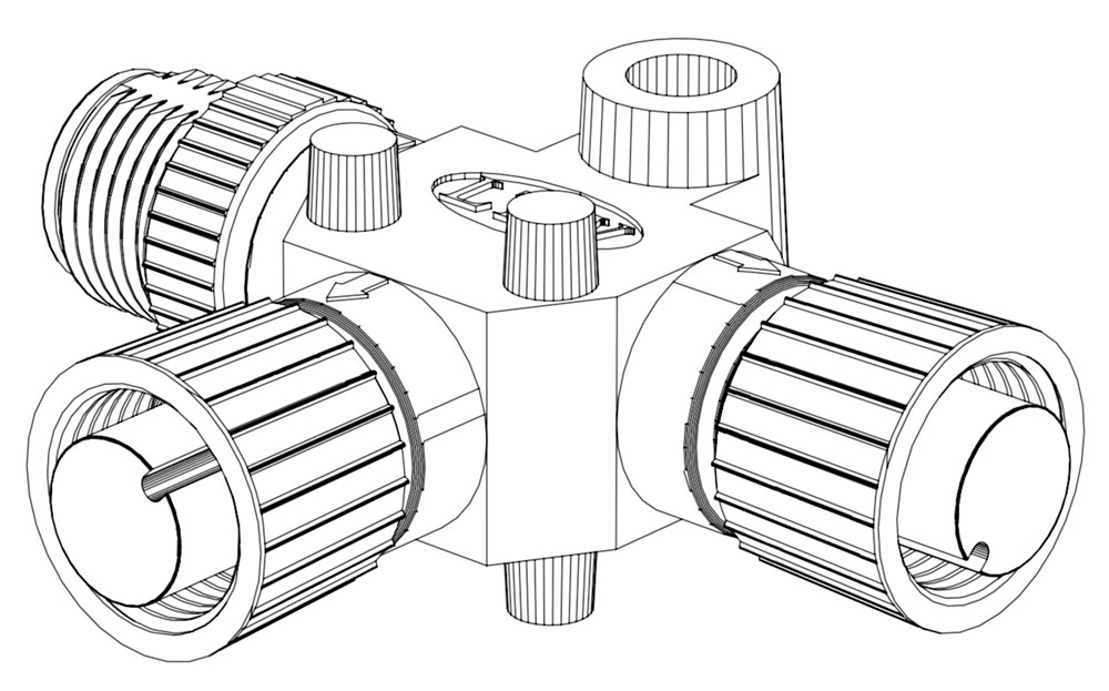
Figure 1 – Electrical Equipment for Seakeeper 2
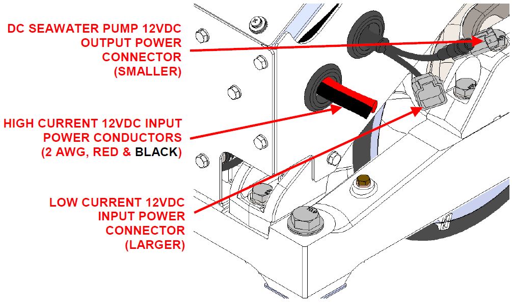
Electrical Equipment Power Connections
High Current 12 V Power Input
High Current 12 VDC Power Source Requirements
| Source | Battery Bank, 12 VDC, Marine, Deep Cycle (AGM battered recommended) |
| Voltage Range | 10 – 15 VDC |
| Continuous Current | 75 A |
| Overcurrent Protection | 100 A (Customer Supplied) |
High Current 12 VDC Power Connection Instructions
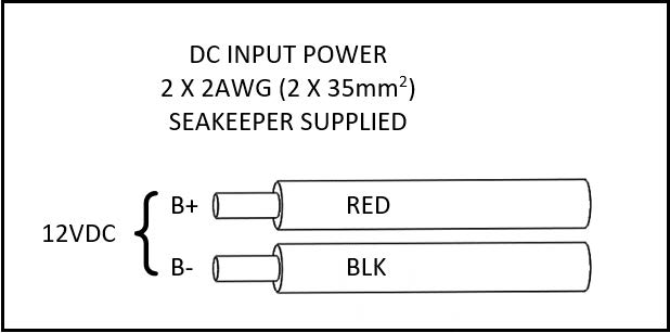
- High Current 2 AWG conductors connect the Seakeeper to the DC source are supplied as length 13ft (4 m). Approximately 3 ft (1 m) is routed inside the Seakeeper frame.
- Conductor length may be increased, but changing from 2 AWG to larger wire size does not allow longer length than 30 ft (9 m) each. The length limit is required to limit the inductance from the high current conductors.
- Use the shortest length and most direct route to the battery bank as possible.
- Bind plus (B+, red) & minus (B-, black) conductors together throughout entire length and do not coil.
- Connect plus conductor (B+, red) through dedicated over-current protection device (customer supplied) and a dedicated isolation switch (customer supplied) then directly to battery plus terminal.
- Connect minus conductor (B-, black) directly to battery minus terminal.
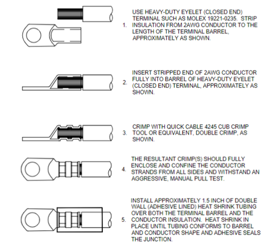
- If the 2 AWG high current 12 V power input conductors are shortened or lengthened, use heavy-duty eyelet (closed end) terminal such as Molex 19221-0235 and follow instructions on Seakeeper Drawing No. 90470 – Seakeeper 2 Cable Block Diagram, sheet 2.
- The bare wire strands should extend fully into the barrel of the heavy-duty eyelet and be crimped in two places if possible then sealed with double-wall heat shrink tubing. Crimp heavy-duty terminals with Quick Cable 4245 Crimp Tool, Molex 19284-0034 Crimp Tool, or equivalent using manufacturer’s instructions.
Low Current 12 V Power Input
Low Current 12 VDC Power Source Requirements
| Source | Battery Bank, 12 VDC, Marine, Deep Cycle |
| Alternate Source | Power Supply / Battery Charger, 12 VDC |
| Voltage Range | 10 – 16 VDC |
| Continuous Current | 9 A |
| Overcurrent Protection | 15 A (Customer Supplied) |
Low Current 12 VDC Power Connection Instructions
Reversing polarity on the DC power input to the Seakeeper can result in damaging the electronics in the control system.
- Install Seakeeper-provided DC Power Input Cable, (P/N 20248) as Cable 7 to battery bank.
- Connect plus conductor (B+, red) through dedicated over-current protection device (customer supplied).
- Connect minus conductor (B-, black) directly to battery minus terminal.
- Before connecting Cable 7 to Seakeeper, check for proper voltage and polarity with a DC multimeter using Figure 5 below.
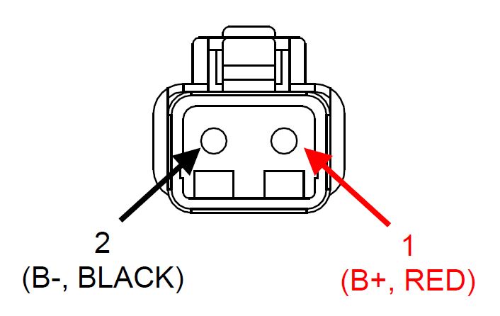
- Connect Cable 7 to Low Current 12 VDC power input connector on the Seakeeper.
When energizing DC power the first time, if display does not power up immediately then disconnect and inspect connector polarity.
DC Seawater Pump 12 V Power Output
DC Seawater Pump 12 VDC Power Source Specifications
| Source | 12 VDC from the Seakeeper |
| Voltage Range | 10 – 15 VDC |
| Continuous Current | On-demand, typically ~10 A |
| Overcurrent Protection | Per pump specification, max 15 A |
DC Seawater Pump 12 VDC Power Input Connection Instructions
- Located the Seawater Pump Power Input Cable (P/N 30327) for Seakeeper 2 “SW Pump DC In” connection on Seakeeper 2 wire harness (as shown in Drawing No. 90470).
- Connect the 16AWG plus conductor (red) through dedicated overcurrent protection device (customer-supplied), maximum of 15A, to dedicated battery isolation switch.
- The High Current, 2AWG B+ conductor (red), is capable of carrying the current for both the High Current, Low Current, and Seawater Pump from the 12VDC power supply to the dedicated battery isolation switch.
- Connect the 16 AWG minus conductor (black) directly to battery minus terminal or DC main negative bus bar.
- Before connecting the SW Pump Power Input Cable to the Seakeeper 2, check for proper voltage and polarity with a DC multimeter using Figure 6 below.
- Connect SW Pump Power Input Cable to Seawater Pump 12 VDC In connector on the Seakeeper, DEUTSCH DT04-2P connector.
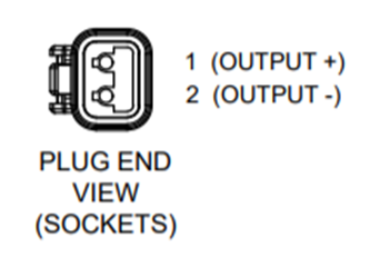
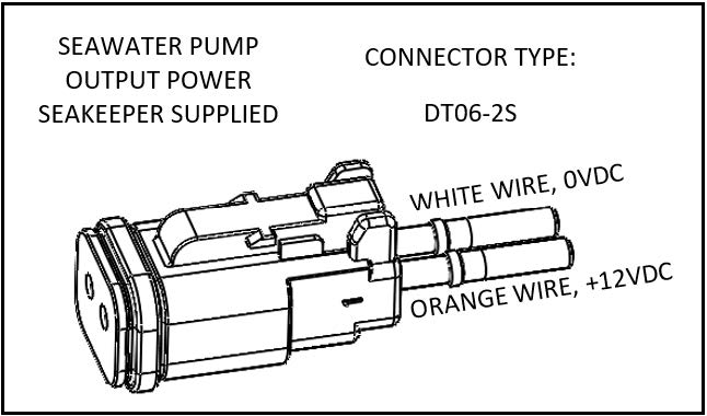
Seawater Pump 12 VDC Power Output Connection Instructions
- Locate the Seawater Pump Power Output Cable (P/N 20334) for “SW Pump 12VDC Out” connection on Seakeeper 2 wire harness (as shown in Drawing No. 90470).
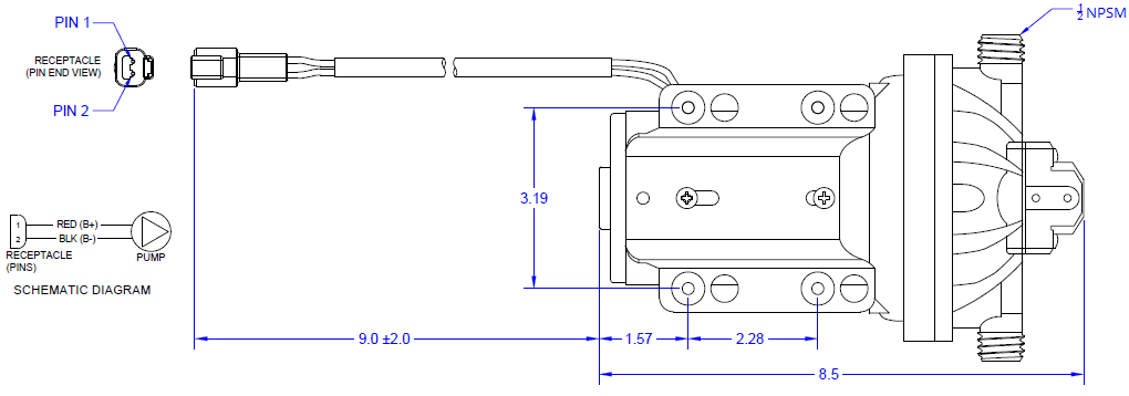
- Pumps rated at 12 VDC, 15 amps maximum, customer-supplied, must be configured with a Deutsch DT series, 2-pin receptacle to mate with the connector as shown in Figure 7.
- TE Connectivity (Deutsch) DT04-2P Receptacle, 2-Way, for Male Pins (qty 1)
- TE Connectivity (Deutsch) 0460-202-1631 Pin, Solid, Gold-plated, Size 16, 16-20 AWG (qty 2)
- TE Connectivity (Deutsch) W2P Wedgelock for 2-Way DT Receptacle (qty 1)
- The Seawater Pump Power Output Cable must be routed and installed in the vessel from the Seakeeper 2 “SW Pump 12VDC Out” Deutsch connector plug (pins end) to the DC seawater pump cable Deutsch connector (socket end).
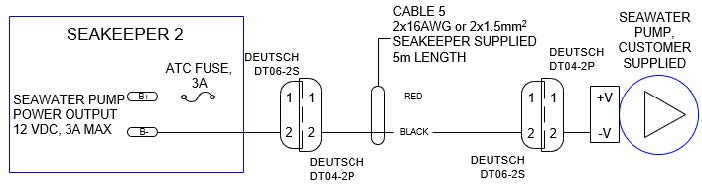
- Connect Seawater Pump Power Output Cable (socket end) to the customer-supplied receptacle end (pins end). The recommended wiring arrangement is shown in Figure 8
- Seakeeper DC Seawater Pump Assembly (P/N 30331), which is prewired for Cable 5, is available as an option with the Seakeeper 2.
Electrical Equipment Ground Connections
Seakeeper to Vessel Ground Connection Instructions
- Connect the Seakeeper foundation ground stud, shown in the following Figure to vessel ground.
- Install Ground Wire (4 AWG or 25 mm2, Customer Supplied) from the M6 brass ground stud on the rear brace to a suitable vessel ground.
- NOTE: ONLY USE THIS LOCATION FOR GROUNDING THE SEAKEEPER TO THE VESSEL GROUND.

Operator Station
This section explains the connection between the Operator Station equipment and the Seakeeper.
Reference Documents & Drawings
- 90470 – Seakeeper 2 Cable Block Diagram
Determine Location of Operator Station
- The desired location of the Operator Station must be determined with respect to the vessel arrangement.
- The operator display should be located on the bridge console.
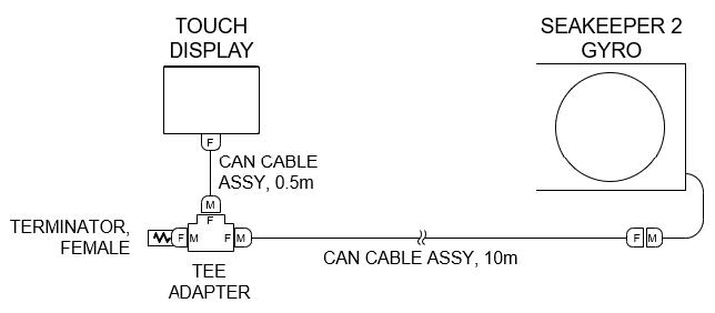
- Figure 11 below shows the CAN bus communications link for the Operator Station. The Terminator goes on the far end of the Tee Adapter from the Seakeeper.
Route CAN Communications Cable
- The CAN Cable Assembly (P/N 30295, Cable 3) is a 10 m shielded cable and the largest connector is a molded plug with maximum outer diameter of .58 in. (14.8 mm).
- Cable 3 must be routed and installed in the vessel from the Seakeeper (female end) to the Tee Adapter (male end) at the Operator Station.
Install Operator Station Equipment
- The Operator Station equipment is installed at the selected location using instructions found in Section: Electrical Equipment Mounting.
Connect Operator Station Equipment
- The Operator Station equipment is connected in accordance with Drawing No. 90470 – Seakeeper 2 Cable Block Diagram.
Electrical Equipment Mounting
Precautions: Each item of electrical equipment has specific mounting instructions. These instructions
should be followed to ensure proper function of the Seakeeper.
Do NOT move Seakeeper mounted components from their
locations or incorrect Seakeeper operation will result.
- Touch Display Mounting Instructions, Surface Mount
- Console space required: Approx. 5.24 W x 3.70 H in. (133 x 94 mm)
- Mounting Instructions, Surface Mount: See Drawing No. 90438 – 5″ Operator Display Envelope and Mounting Details, for details.
- CAN Communications Tee Adapter and Terminator Mounting Instructions
- Console space required, Rear: Approx. 4 W x 3 H in. (102 x 76 mm), rear
- Mounting Instructions: Rear mount on vessel console panel, within 2 ft (0.6 m) of Display.
- Hardware required: One mounting screw for .197 in. (5 mm) diameter mounting hole on Tee Adapter.
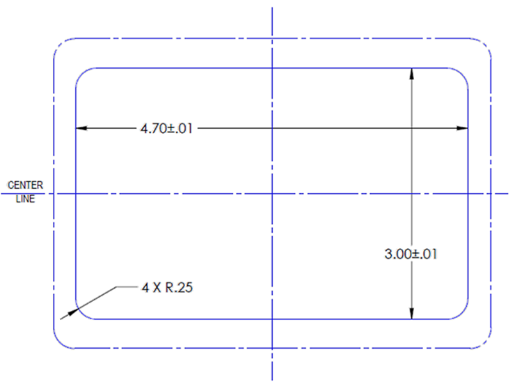
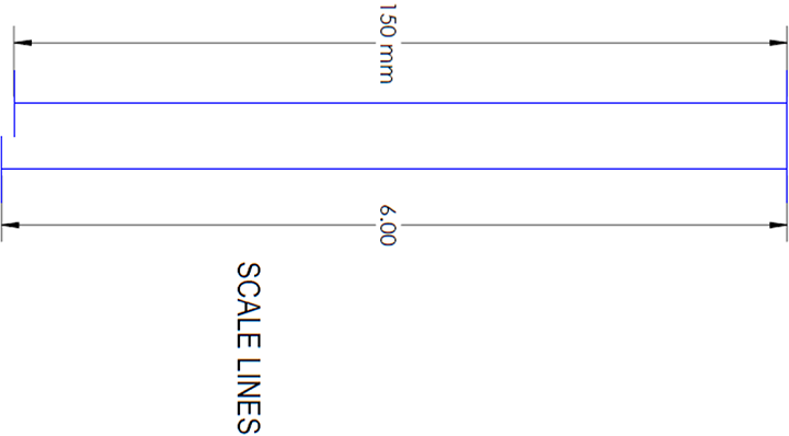
Display Installation Template
The following template is for mounting; before using this template, measure to ensure that the shown size is actual.
Cooling Installation
Cooling Installation Introduction
Reference Documents & Drawings:
Link to Seakeeper 2 Reference Documents
- 90469 – Seakeeper 2 Hardware Scope of Supply
- 90490 – Seakeeper 2 Cooling Water Schematic
- 90470 – Seakeeper 2 Cable Block Diagram
- TB 90191 – Seawater Cooling Pump Recommendations
- 30331 – Seakeeper DC Seawater Pump Assembly
The Seakeeper 2 is shipped with the cooling circuit filled and ready for use. The Seakeeper 2 requires connection to a raw water pump, referred to as the seawater pump, to cool the closed loop cooling circuit on the unit. The required seawater flow through the Seakeeper 2 heat exchanger is between 2 – 6 GPM (7.6 – 22.7 LPM), under all vessel operating conditions. Prior to operation, confirmation of glycol level is required.
Seakeeper offers a compatible self-priming DC Seawater Pump (P/N 30331) that is prewired for the Seakeeper 2 Installation and covered under the standard Seakeeper warranty. See Drawing No. 30331, SeaFlo Seawater Pump Assembly for details and the Seakeeper Options and Accessories Price List for pricing information.
Installation Considerations
- The installer is responsible for supplying a dedicated seawater pump and associated plumbing. An optional seawater pump can be purchased through Seakeeper, P/N 30331.
- Seawater connections on the Seakeeper heat exchanger mate with ¾ in. (19 mm) hose.
- The seawater pump is powered via the “SW Pump 12 VDC Out” connection on the Seakeeper 2 wire harness, as outlined in Electrical Installation Section.
- The seawater pump operates on 12 VDC with a max overcurrent protection rating of 15 A.
- A dedicated through-hull fitting should be installed for each Seakeeper unit onboard the vessel to ensure sufficient seawater flow to each unit.
- It is recommended that the seawater pump is located below the waterline, as close to the baseline of the vessel as practically possible, to maintain positive inlet pressure on the pump in all operating conditions.
- A self-priming seawater pump may be required to maintain water flow in all underway conditions. Cavitation can occur at the seawater inlet and potentially cause an air-lock condition restricting seawater flow to the heat exchanger.
- Maximum allowed seawater pressure in heat exchanger is 20 psi (1.4 bar)
- Seawater flow requirement through heat exchanger is 2 GPM (7.6 LPM) minimum and 6 GPM (22.7 LPM) maximum under all operating conditions of the boat. When sizing seawater pump, installer should factor in losses for raw water plumbing. In addition to initial operation at dock, new Seakeeper installations should be checked to be within the flow requirements while vessel is at speed. Flows higher than 6 GPM (22.7 LPM) could affect heat exchanger life.
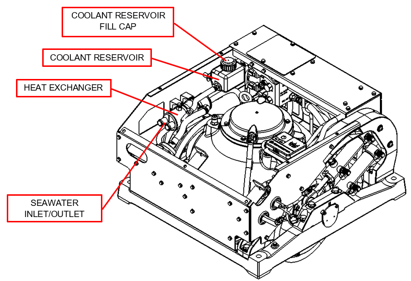
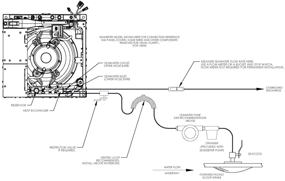
Connecting Seawater to Heat Exchanger
Refer to Figure 2 for typical seawater plumbing arrangement.
- Connect seawater pump to Seakeeper dedicated through-hull fitting. A strainer and seacock valve should generally be installed between the seawater inlet and the pump.
- Connect seawater from installer supplied pump to lower 3/4 in. (19 mm) hose barb on heat exchanger. Use the same practices as other below waterline seawater plumbing.
- Connect seawater discharge to overboard drain. Use the same practices as other below waterline seawater plumbing.
- Required flow rate is 2 GPM (7.6 LPM) minimum and 6 GPM (22.7 LPM) maximum.
- In addition to initial operation at dock, new Seakeeper installations should be checked for minimum 2 GPM (7.6 LPM) flow while vessel is at speed and when backing down.
- If no other method of confirming flow is available, discharge line may be temporarily diverted to a bucket. Flow is calculated from time to fill a known volume.
- Flowrates in excess of 6 GPM (22.7 LPM) could affect heat exchanger life.
- Inspect raw water plumbing after sea trial for any signs of leakage.
Seakeeper Optional DC Seawater Pump
- Seakeeper offers a self-priming DC Seawater pump as an optional addition, P/N 30331 – DC Seawater Pump Assembly, shown in the following Figure.
- The Seakeeper Seawater Pump is a 24 VDC pump operated at 12 VDC for the Seakeeper 2 and maintains a seawater flow of approximately 2.5 GPM (9.5 LPM) at 12 VDC.
- The pump assembly is pre-wired for connection to Seakeeper 2 Cable 5 and includes a seawater strainer and various fittings. The pump specifications are as follows:
| Volts | 24 VDC (intended for 12 VDC operation with Seakeeper 2) |
| Flowrate | 2.5 GPM (9.5 LPM), at 12 VDC |
| Overcurrent Protection Rating | 15 A |
| Ignition Protection Rating | ISO 8846 or equivalent |
NOTE: Use only SeaFlo-provided threaded fittings for DC Seawater Pump 30331.
Adding Coolant
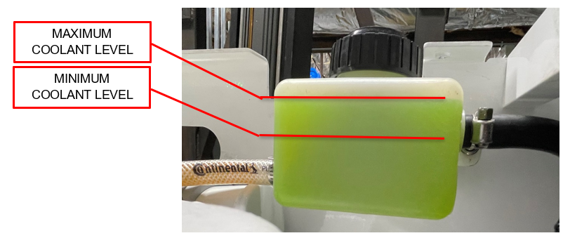
- The Seakeeper 2 cooling system is filled to proper level when shipped. If level has dropped, check for evidence of leaks at all connections before adding fluid as described below. If coolant is at the correct level, skip to Step 5.
- The minimum and maximum glycol fill levels are shown in Figure 4.
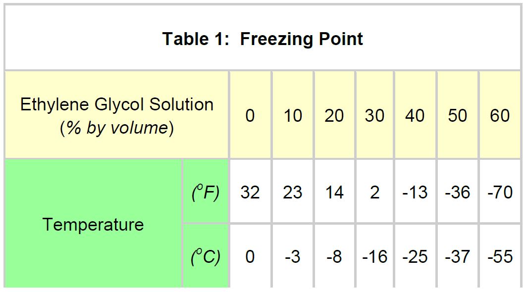
- Mix 50% ethylene glycol with 50% distilled water in a clean container. Refer to Table 1 or glycol manufacturer’s literature for freezing points.
- It is required that ethylene glycol with corrosion inhibitors be used. Most commercially available glycol has these additives standard.
- Remove reservoir cap and pour mixture in until level reaches top face of the reservoir enclosure, as shown in Figure 4.
- Filling reservoir above this level will not cause any damage but coolant may be expelled from the vented cap due to normal thermal expansion of coolant.
- Once the Seakeeper 2 and DC seawater pump are connected to 12 VDC power:
- Check the Seakeeper Display interface for any ALARMS.
- Cycle the Seakeeper 2 power, and press the POWER ON button.
- The flywheel will start to spin, and the glycol pump will start.
- Recheck glycol level with fluid circulating in coolant circuit to ensure the correct fill level is maintained.
- After several minutes of running, press POWER OFF button.
- The cooling system is self-purging. If small amounts of air are in the system, they should be dislodged during the first sea trial. Recheck level after sea trial and add fluid if required.
Start Up
Start Up Introduction
This section describes the first start up of the Seakeeper.
Reference Documents & Drawings:
Link to Seakeeper 2 Reference Documents
- 90489 – Seakeeper 2 Operation Manual
- Previous sections for mechanical, electrical and cooling installation must be completed before this start up sequence is initiated.
- Before continuing, covers must be installed unless the Seakeeper is inaccessible and there is no risk to injury. Also, the area around the Seakeeper must be clear of personnel and equipment.
Start Up Instructions
- Energize 12 VDC 15 A supply at the customer-supplied electrical disconnect.
- Supply 12 VDC 100 A to Motor Drive Box at customer-supplied electrical disconnect.
- If seawater pump for the Seakeeper is not supplied through cable from Motor Drive Box, turn on the boat’s DC dedicated circuit breaker that supplies power to the seawater pump.
- With system powered up check the display for any ALARMS. If there are any ALARMS present they must be corrected first.
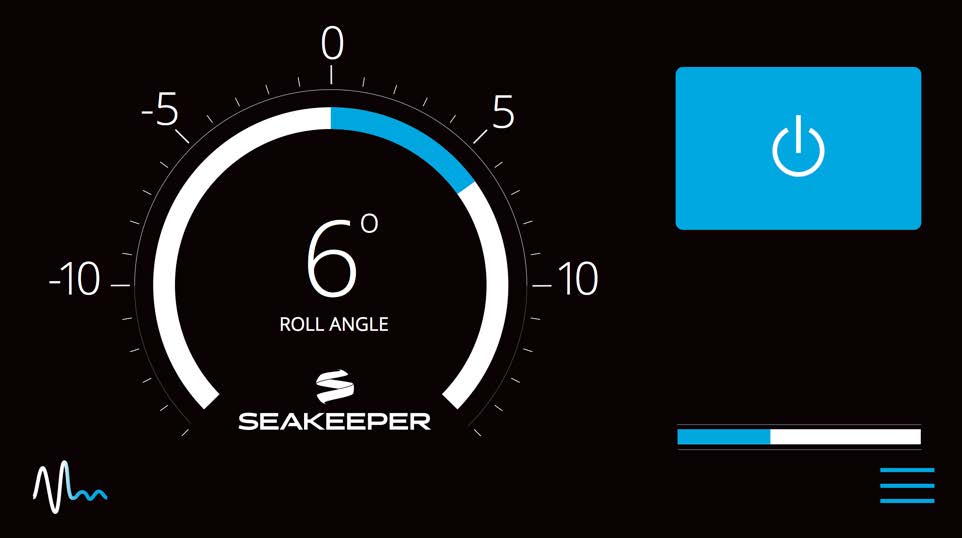
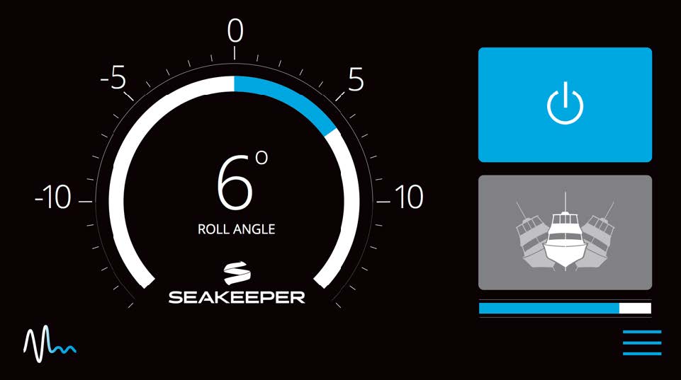
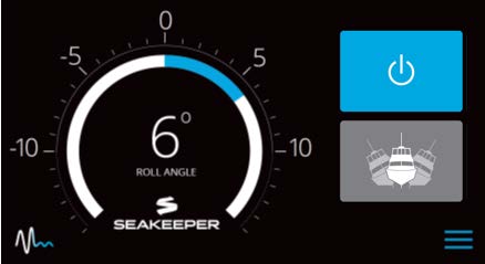
- Press the Seakeeper ON/OFF Button on Display.
 The progress bar will appear and indicate how soon the Seakeeper will be available for stabilization. When the Seakeeper is initialized and up to minimum operating speed the STABILIZE button will appear. At this point, the Seakeeper is available for stabilization.
- The seawater pump will operate for two minutes after the ON/OFF button on the display was depressed. After that the seawater pump output is turned on and off based on the temperature of the Seakeeper. Confirm pump operation and flow rate, if practical. Required flow is 2 GPM (7.6 LPM) minimum and 6 GPM (22.7 LPM) maximum.
- Verify that there are no ALARMS present. If an ALARM is present it will be displayed.
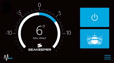
- When the Seakeeper reaches its maximum operating speed where maximum stabilization is available, the progress bar will disappear and the Seakeeper is available for maximum stabilization. Press the STABILIZE button.
 The button will turn blue indicating that the Seakeeper is stabilizing the roll motion.
- Verify that there are no ALARMS. If an ALARM is present it will be displayed.
- Press the STABILIZE Button
 to turn stabilization off. Then press the Seakeeper ON/OFF Button
  to power the Seakeeper down.
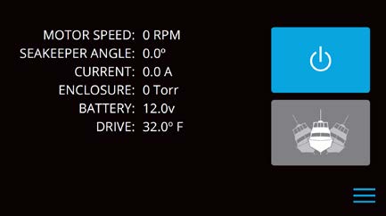
 - During normal operation, the Seakeeper should be stopped when stabilization is no longer required. This maximizes long term life as it allows the Seakeeper to start the coast down cycle before cooling is shutoff. Once the vessel is secured in the slip and the crew has shut down the generator and engines, the DC breakers that control the Seakeeper should be switched to the OFF position. The Seakeeper will continue to spool down to 0 RPM. No cooling is required during this time. Note the Seakeeper 2 will take 16+ hours to coast down to 0 RPM from full speed. When the flywheel has stopped the service screen will indicate 0 RPM.
Installation Checklist and Required Supplies
Installation Checklist
Mechanical Checklist
(Reference Installation Manual Section: Mechanical Installation)
- Seakeeper foundation installed in hull
- Seakeeper supplied foundation bolts torqued to specification
- Clearances around Seakeeper meet specifications and no obstructions are within the Seakeeper envelope
Electrical Checklist
(Reference Seakeeper Drawing No. 90470 – Seakeeper 2 Cable Block Diagram & Installation Manual Section: Electrical Installation)
Mount Components
- Display (near helm)
Connect Seakeeper and Customer Supplied Cables
- Cable 7 (Seakeeper Supplied)
- Connect Cable 7 from Seakeeper 12 VDC 15 A power at customer-supplied connection box, or directly to a circuit breaker.
- Plug connector of Cable 7 into mating connector on the Seakeeper wire harness.
- Cable 6 (Customer Supplied)
- Install lugs on both ends of customer-supplied 4 AWG ground cable.
- Connect one end of Cable 6 to nearest vessel ground and other end to Seakeeper foundation.
Connect Seakeeper Supplied Cables
- Conductors 1&2 (Seakeeper Supplied)
- Connect Conductors 1&2 from Drive Box to 12 VDC 100 A at customer-supplied connection box or directly to circuit breaker.
- Cable 5 (Seakeeper Supplied)
- Connect female end of Cable 5 to customer supplied 12 VDC 3 A seawater pump.
- Plug male end connector of Cable 5 into mating connector on the Seakeeper wire harness
- Cable 3 (Seakeeper Supplied)
- Connect female end of CAN communications Cable 3 to mating connector on the Seakeeper wire harness
- Route CAN communications Cable 3 from the Seakeeper to helm (male end goes to helm)
- Connect male end of CAN communications Cable 3 at helm to CAN Tee Adapter
- Connect Display and Seakeeper-supplied Cable 4 to CAN Tee Adapter with CAN Terminator
Cooling Checklist
(Reference Installation Manual Section: Cooling Installation)
- Verify coolant level in heat exchanger coolant reservoir.
- Connect seawater hoses / open sea cocks to heat exchanger and test seawater pump.
- Verify 2 GPM (7.6 LPM) minimum and 6 GPM (22.7 LPM) maximum seawater flow through heat exchanger under all operating conditions of the boat. (The seawater pump output will operate for two minutes after the Seakeeper is turned on. During operation, the seawater pump output is turned on and off based on the temperature of the Seakeeper)
Start Up Checklist
(Reference Installation Manual Section: Start Up & Operation Manual Section: System Operation)
- Remove lifting bolts and install cover panels
- Turn on 12 VDC 15 A circuit breaker
- Turn on 12 VDC 100 A circuit breaker
- Verify display works and no ALARMS are present
- If display does not work, turn off both circuit breakers immediately
- Check polarity of 12 VDC 15 A power per Section 2.2.5
- Follow instructions in Installation Manual Section: Start Up Instructions, to turn on the Seakeeper
- Verify seawater pump turns on when the Seakeeper is turned ON
- Verify that no ALARMS are present
- Follow instructions in Installation Manual Section: Start Up Instructions, to turn off the Seakeeper
- DC power and seawater pump may be turned off after the Seakeeper is turned off by placing the Seakeeper in LOCK mode and turning the Seakeeper off
- Seakeeper 2 takes 16+ hours to coast down to 0 RPM from full speed
Required Supplies Needed for Seakeeper Installation
(Not Supplied With the Seakeeper)
| Item | Description | Qty | Installation Manual Reference Section | Other Reference | System |
|---|---|---|---|---|---|
| 1 | Soundproofing Considerations | Selection of Installation Location | Mechanical | ||
| 2 | Spreader bar for lifting the Seakeeper | 1 | Transport and Unpacking | Mechanical | |
| 3 | Hose clamps for seawater plumbing to ¾ in. (19 mm) hose barb (2 per hose barb) | 4 | Connecting Seawater to Heat Exchanger | Cooling | |
| 4 | M6 terminal lug for grounding Seakeeper at rear brace | 1 | Electrical Equipment Ground Connections | Dwg 90470 | Electrical |
| 5 | Cable, 4 AWG, for grounding Seakeeper at foundation to vessel ground (used with item 4) | AR | Electrical Equipment Ground Connections | Dwg 90470 | Electrical |
| 6 | Seawater pump, 12 VDC, 15A max | 1 | Electrical Equipment DC Pump Power | Dwg 90470 | Electrical |
| 7 | Pump over current protection, per pump spec | 1 | Electrical Equipment DC Pump Power | Dwg 90470 | Electrical |
| 8 | 100 A Circuit breaker for Conductor 1 | 1 | Electrical Equipment High Current Power Input | Dwg 90470 | Electrical |
| 9 | 15 A Circuit breaker for Cable 7 | 1 | Electrical Equipment Low Current Power Input | Dwg 90470 | Electrical |
AR = As Required
Dwg = Drawing
List of Common Tools That May Be Required for Installation
| Item | Description | Use |
|---|---|---|
| 1 | Wire cutter | DC Power cables |
| 2 | Wire stripper | DC Power cables |
| 3 | 3 mm hex key | Gimbal sensor mount plate |
| 4 | 2.5 mm hex key | Gimbal angle sensor |
| 5 | ¼ in. nut driver | Hose clamps |
| 6 | Quick Cable 4245 Crimp Tool, Molex 19284-0034 Crimp Tool, or equivalent | Power cables |
| 7 | Utility knife | Scoring cable jackets |