Seakeeper 18 Installation Manual (90672-2); S/N 18-234-1475 to 18-254-2134
2.5 Saddle Installation
Seakeeper provided mounting hardware is intended to apply to typical installation arrangements. However, each installation, especially custom aftermarket foundations, should be thoroughly reviewed to ensure the provided hardware meets the required thread engagement for the Seakeeper unit being installed. The mounting bolt thread engagement requirements are outlined in the Installation Manuals and Installation Details Drawings for each Seakeeper model. This also applies to Seakeeper model adapter kits and OEM built frames where the bolt hole depth should be checked to ensure the bolts will not bottom, preventing the bolts from achieving the intended preload.
When the Seakeeper provided hardware is not appropriate, the bolt specification (diameter and thread pitch) and grade should be matched in the required length and used with the Seakeeper provided washers. Mounting bolts should always be torqued to the Seakeeper specification. All Seakeeper provided bolts are metric course thread. Hardware specifications are also listed in the Installation Manuals and Installation Details Drawings.
See Sheet 6 of Seakeeper drawing No. 90545 for loads information and recommended adhesive properties.
2.5.1 Preparation of Hull Structure
Refer to Seakeeper Drawing No. 90545, Seakeeper 18 Installation Details – Bond-In Method. Important dimensional and load information is given in this drawing that will impact the design details of the structure that will receive the Seakeeper as well as selection of the adhesive to bond the Seakeeper into the hull.
The foundation “saddles” of the Seakeeper are designed to be bonded directly to the composite hull structure of the vessel to effectively distribute Seakeeper loads. A complete bond is required between the inside surface of the saddles and the hull structure. An estimate of adhesive volume required should be calculated for each installation based on gaps between saddles and structural members. There is some adhesive waste as a part of the process, so a good rule of thumb is to purchase up to 50% more adhesive than estimated volume to ensure a complete bond. Depending on conditions and adhesive used, two workers may be required to apply the adhesive at the same time to finish the installation before the adhesive starts to cure. To aid in determining the quantity of adhesive required, the interior surface area (bonding surfaces) of each saddle is 164 in.2 (1,058 cm2) for a total bonded surface area for all four saddles of 656 in.2 (4,232 cm2).
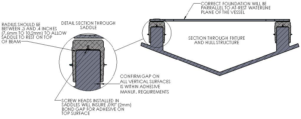
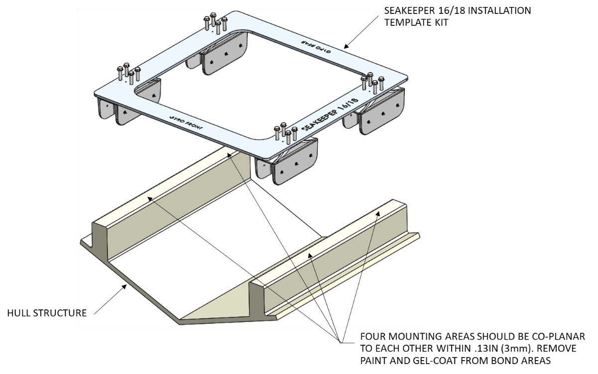
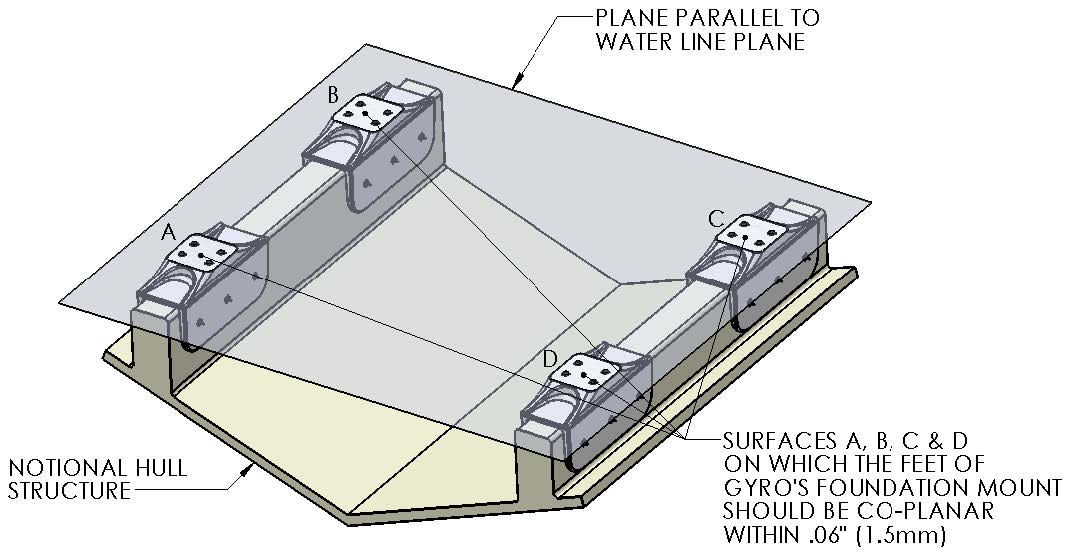
The hull structure supporting the Seakeeper should be arranged so the Seakeeper is parallel to the waterline in the transverse direction and within 2 degrees longitudinally. The four areas on top of the beams that the saddles will bond to need to be co-planar within .13 in. (3 mm) for consistent adhesive bond gap. In addition, the four areas on top of the saddles on which the feet of the Seakeeper foundation will rest need to be co-planar within .06 in. (1.5 mm) to minimize potential distortion of Seakeeper support frame when installed.
Note that any paint or gelcoat present in bond area should be removed so that adhesive will bond directly to laminate fibers and resin.
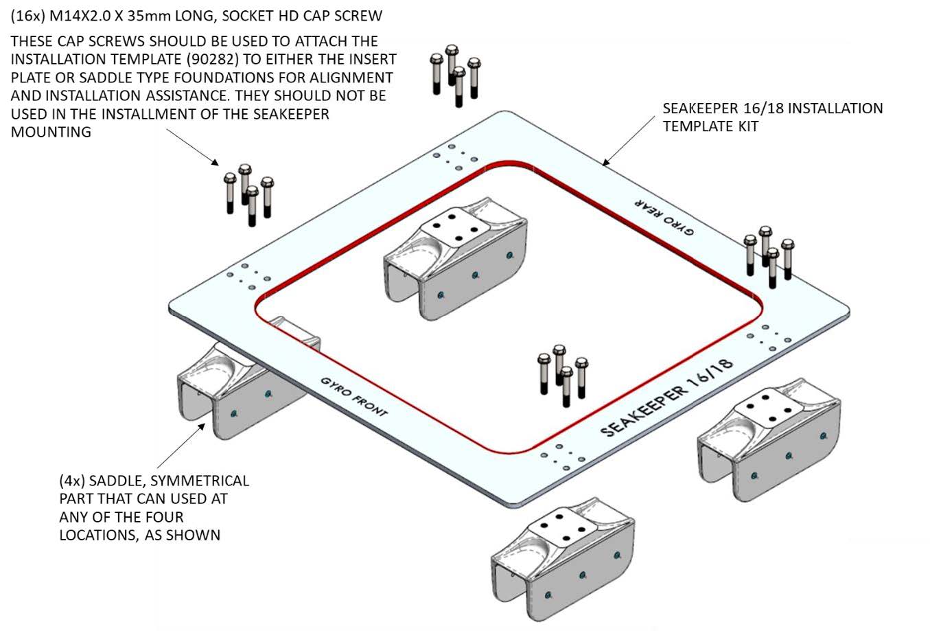
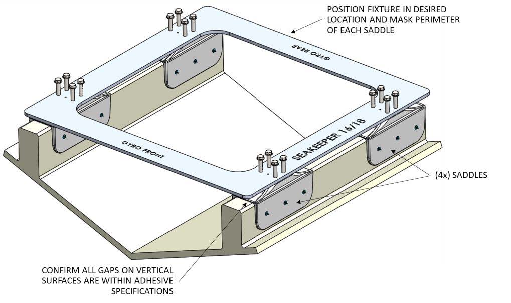
Seakeeper provides an installation fixture template, P/N 90282 that locates the saddles at the proper spacing both in the fore-aft direction and the port-starboard direction. See Figures 10, 11, & 12. Once assembled with the provided saddle fittings, the fixture can be used to check clearances and alignment of the hull structure. The fixture will allow the builder / installer to lay-up and adjust the foundation dimensions to create a low-clearance fit between the Seakeeper foundation saddles and the hull structure. Shear strength of the adhesive will be maximized if the cured thickness between the vessel structure and Seakeeper saddles is at the thinner end of the adhesive manufacturer’s recommended range. Therefore, the fixture should be used to confirm that the overall dimensions of the foundations are square and level and that the adhesive gap is within Seakeeper’s recommended range of .04 to .13 in. (1 to 3 mm).Note: Do NOT use the installation fixture to establish Seakeeper envelope dimensions. Refer to Drawing No. 90545 for envelope dimensions. A 3-D model of the Seakeeper is available on the Seakeeper Technical Library (www.seakeeper.com/technical-library/) to aid in designing the Seakeeper foundation and the space around the Seakeeper.
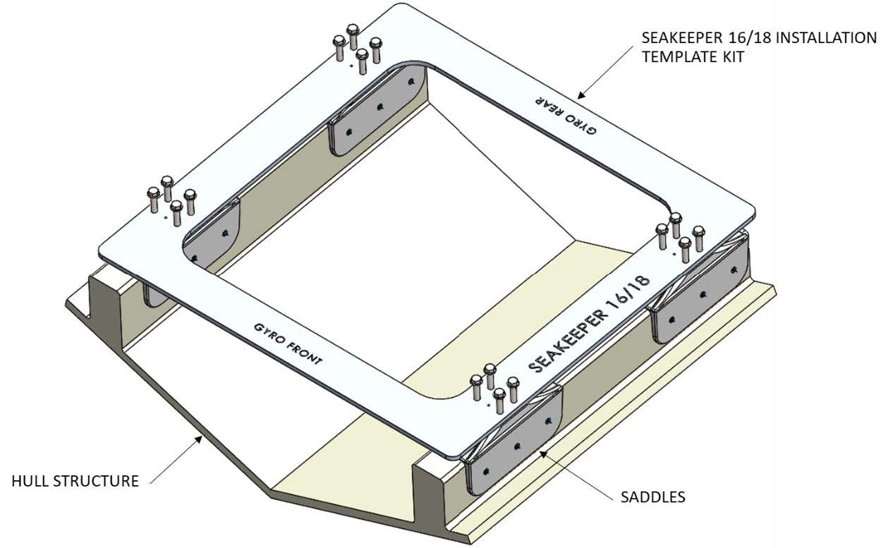
NOTE: MAKE SURE NO OBSTRUCTIONS FROM THE HULL STRUCTURE CAN BE SEEN WITHIN THE INSIDE OF THE INSTALLATION TEMPLATE KIT (INSIDE THE MARKED RED LINES). REFERENCE SEAKEEPER DRAWING NO. 90545.
2.5.2 Fiberglass Hull Preparation
- Position installation fixture (Figure 12) on hull girders noting recommended clearances for maintenance from Figure 3. Check that the screws fastening the saddles to the installation fixture are tight (Figure 14).
- Mask hull area (Figure 13) around foundation saddles for easy clean-up and to create outline of surface area to receive adhesive as (Figure 12). Ensure that the bond gap is within Seakeeper’s recommended thickness, or 3 mm if using Plexus MA590.
- Raise fixture clear of foundation. Check all four mounting areas are co-planar to within 0.13 in. (3 mm) to each other, as well as parallel to the water line plane, as shown in Figure 14.
- Thoroughly clean with alcohol or acetone all areas of girders to be bonded to remove any contaminates. Use new paper towels for cleaning, not shop rags.
- Remove any paint or gelcoat from bond surfaces so that adhesive will bond directly to laminate fibers and resin as shown in Figure 13.
- Thoroughly sand hull girder bond surfaces with 80 grit sandpaper. (IMPORTANT – BOND STRENGTH MAY BE REDUCED IF THIS STEP IS SKIPPED.)
- Wipe surfaces clean from dust with alcohol or acetone using new paper towels, not shop rags.
- Re-position installation fixture on girders and double-check that the adhesive gap is within the adhesive manufacturer’s maximum recommended thickness. Seakeeper recommends a maximum gap of 3 mm if using Plexus MA590.
Note if bonding saddles to a metal structure, contact Seakeeper for hull preparation instructions.
2.5.3 Seakeeper Saddle Preparation
- Ensure that screws fastening saddles to the installation fixture are tight (Figure 11).
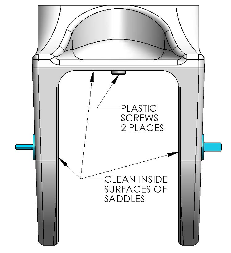
- Check that each saddle contains 2 plastic screws which will ensure an adhesive gap of .080 in. (2 mm) on top surface of hull as shown in Figure 15. Do not remove these screws.
- Thoroughly sand all saddle inside surfaces with 80 grit sandpaper in cross-hatch pattern. (IMPORTANT – BOND STRENGTH MAY BE REDUCED IF THIS STEP IS SKIPPED.)
- Thoroughly clean with alcohol or acetone the inside surfaces of Seakeeper foundation saddles to remove any contaminates as shown in Figure 11. Use new paper towels for cleaning, not shop rags.
- If using Plexus MA590 adhesive, apply one coat of Plexus PC-120 surface conditioner to inside surfaces of Seakeeper foundation saddles in accordance with manufacturer instructions. These instructions are located in the following section. If using an alternate adhesive, check with manufacturer if any surface conditioner/etch is required for the aluminum saddles.
2.5.4 Bonding Saddles to Hull
Note: This is a sample if using Plexus, if using another adhesive follow manufacturer’s
recommendations. If using Plexus MA590 adhesive, the Seakeeper saddles should be installed when PC-120 is confirmed dry.
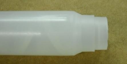
- Assemble Plexus cartridge into either the manual or pneumatic gun as shown. Remove cap on cartridge and attach mixing tip. For pneumatic gun, start with low air pressure and increase until desired flow rate is achieved.
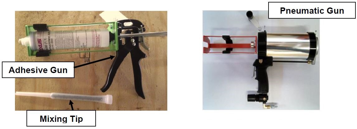
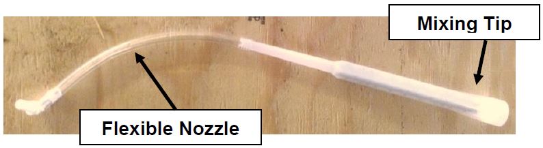
- Cut tip of mixing wand as shown in photo.
- Prepare a second mixing wand as shown in photo below by attaching the simple flexible nozzle to the end of the mixing tip. Set aside for now as this will be used to inject adhesive into the sides of each saddle after the fixture / saddles are in position.
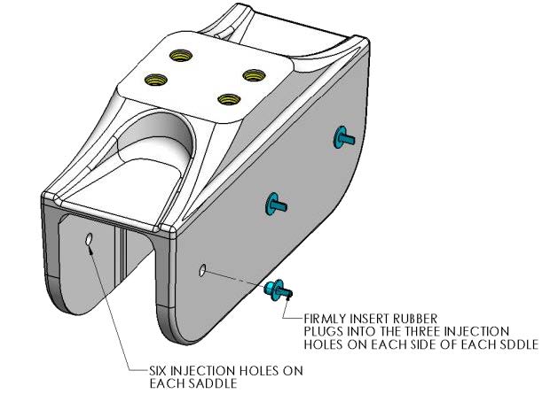
- Install provided rubber plugs in six holes of each saddle. The plugs will limit the adhesive being forced out of the injection holes in step 6 below.
- Apply large bead of Plexus adhesive to the hull structure as shown in the figure to the right. Apply approximately 2/3rds to 1 cartridge at each of the four locations. Work deliberate and fast as it takes some time to apply the adhesive to the structure. MA590 has a 90-minute working time at room temperature (73°F / 23°C). This working time can reduce to 40-50 minutes at elevated temperatures. Two workers should apply the adhesive at the same time to finish the installation before the adhesive starts to cure.
- Lower fixture and saddles over the hull structure and apply light downward pressure to each of the four saddles until the two nylon screws rest on the hull structure (SEE FIG. 7). The adhesive will be forced towards the forward and aft ends of each saddle and partially down the sides of the foundation beams.
- Insert full adhesive cartridge along with mixing wand / nozzle assembled in Step 3 above into gun.
- Begin to inject adhesive into the three holes provided on each side of each of the four saddles. Follow the numbered sequence shown until the adhesive pushes out the edges of the saddle perimeter. The intent is to pump in the adhesive working from the top down and from the middle to the ends to fill the gaps and displace any air.

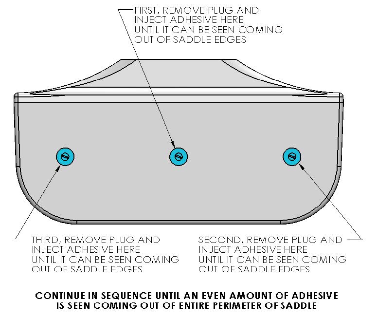
A complete bond is required – excess adhesive will be needed to make sure all bond gaps are filled.
- Repeat above step for remaining 7 sides of the saddles.
- When gaps have been completely filled, clean off excess adhesive, remove plugs, and remove masking tape.
- Allow adhesive to cure per manufacturer’s recommendations. Follow adhesive guidelines for curing time versus temperature prior to removing the fixture.
- Bonding of Seakeeper saddles onto the hull is now complete. Remove installation fixture.
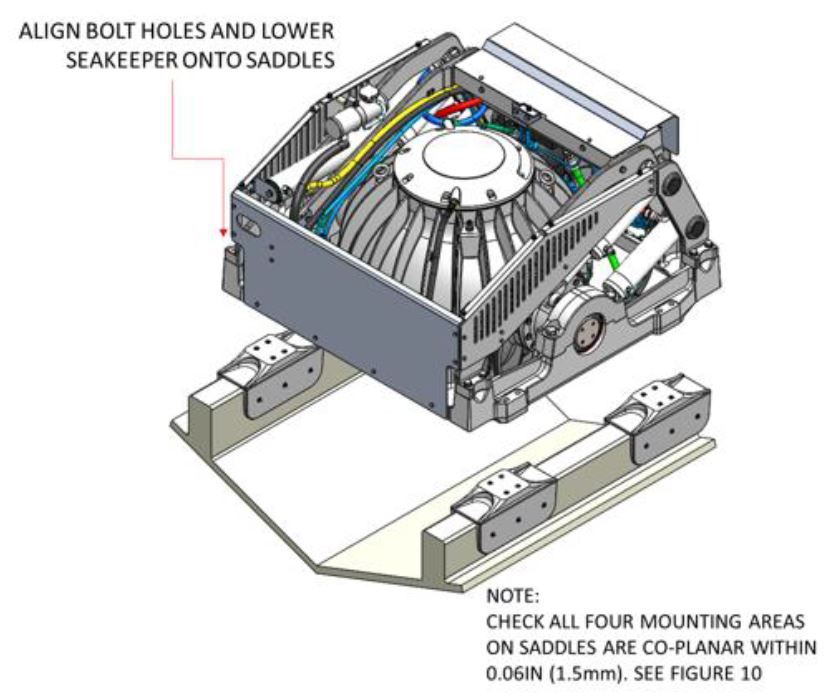
2.5.5 Installation of Seakeeper
- The four areas where the feet of the Seakeeper will rest should be coplanar to within .06 in. (1.5 mm). See Figure 14.
- Rig the Seakeeper for lifting and lower it into position onto top surface of four saddles.
- Apply a small bead (approximately 4 mm wide) of sealant or caulk to the mating surfaces between the saddles and the Seakeeper foundation. Adjust position of the Seakeeper until alignment is achieved for the 16 fasteners that will attach Seakeeper foundation frame to saddles.
- Install the Seakeeper supplied Grade 10.9, M14-2.0 x 90 mm fasteners or alternative Grade 10.9, M14-2.0 bolts to maintain a minimum thread engagement of .83 in (21 mm). Apply a moderate coat of nickel-based anti-seize (e.g., SAF-T-EZE nickel grade anti-seize, SBT-4N or equivalent) to the threads of each bolt and include a small bead of marine grade sealant (e.g., SILI-THANE 803 or equivalent) under each bolt head and washer before installation.
- Torque all fasteners to 100 ft-lbs (136 N-m).
- New bolts, matching the Seakeeper specification, must be used for each installation and reinstallation that meet the requirements listed above.
- Proceed to electrical and cooling portion of the installation.