Seakeeper 1 Operation Manual (90520-1) 1-202-0001 to 1-233-0630
System Operation
System Operation Introduction
The Seakeeper 1 requires the ConnectBox as well as connection to either a compatible MFD or an optional Seakeeper 5” Touch Display. Both compatible MFD and the Seakeeper 5” Touch Display will show the same Seakeeper Application outlined in this section.
Display Screens and ConnectBox Overview
Display Screens and ConnectBox Overview Introduction
When 12 VDC power is applied to the Seakeeper, the ConnectBox will illuminate and the Seakeeper Application on the 5” Touch Display and/or MFD will initialize. If connecting the ConnectBox to an MFD, and the Seakeeper App does not appear on the MFD, please refer to appropriate Technical Bulletin to troubleshoot, at www.seakeeper.com/technical-library/ and filter for the Seakeeper 1:
ConnectBox and Home Screen
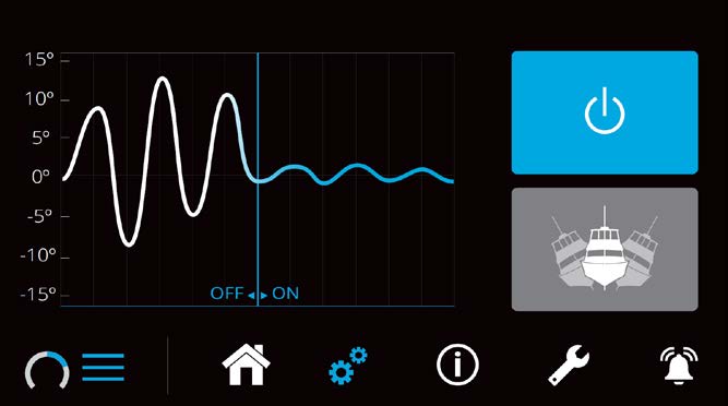
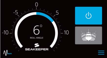
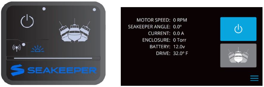
- After the Seakeeper ConnectBox and Application have initialized, the ConnectBox and Application Home Screen will be displayed as shown below.

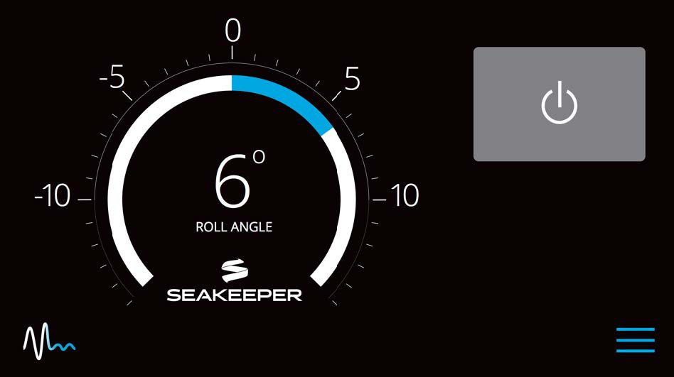
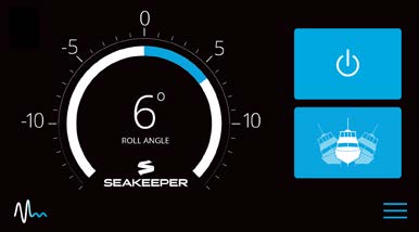
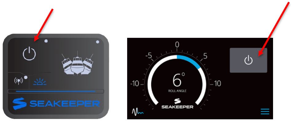
- The Seakeeper can be controlled by either the ConnectBox (shown in the left pictures) or the Application on the Seakeeper 5” Touch Display or compatible MFD (shown in the right pictures). Seakeeper POWER button: when pressed, the button will change from grey (Seakeeper Off) to blue (Seakeeper On).
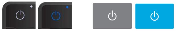
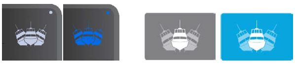
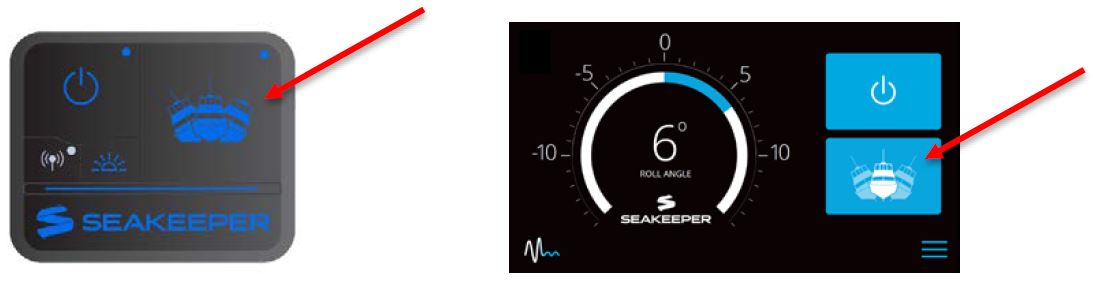
- Seakeeper STABILIZE button: when pressed, the button will change from grey (Stabilize Off) to blue (Stabilize On).
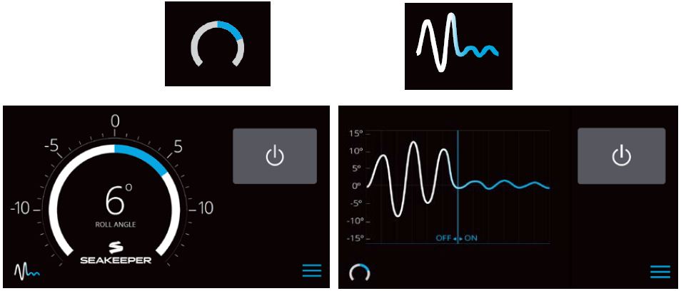
- On the Application Home Screen view, these buttons can be pressed to toggle Home Screen views between the Roll Angle Gauge and the Roll Angle Graph as shown below.
- When the MENU button is pressed,
 the Menu Bar will appear or disappear at the bottom of the screen.
- The Menu Bar is used to navigate between pages. From left to right, the available pages are Home, Settings, Information, Service, and Alarm History. The selected page is highlighted in blue on the Menu Bar.

Settings Page
- The Settings Page allows the user to adjust their preferences for the Seakeeper and its display. It can be accessed by pressing the gears
 in the menu bar.
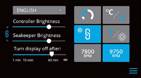
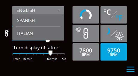
- The language on the Seakeeper Application can be changed using the Settings Page. By clicking ENGLISH, a dropdown appears, and the desired language can be selected.

- The brightness of the Seakeeper LED lights, ConnectBox, and display can be changed individually or synchronized to the local controller (either the Seakeeper 5” Touch Display or the ConnectBox) brightness by pressing the SYNCHRONIZE BRIGHTNESS Button from grey (SYNC BRIGHTNESS Off) to blue (SYNC BRIGHTNESS On).

- When the SYNC BRIGHTNESS Button is Off, the local controller, ConnectBox, and Seakeeper brightness can be controlled individually. The ConnectBox brightness can be controlled by pressing the BRIGHTNESS button
 on the ConnectBox. To increase or decrease the brightness of the Seakeeper 5” Touch Display, slide the white dot left to decrease brightness and right to increase brightness on the brightness bar, pictured below on the Settings Page.

- When the SYNC BRIGHTNESS Button is Off, increase or decrease the brightness of the LED Seakeeper lights with the brightness slider by sliding the white dot left to decrease brightness and right to increase brightness. When the SYNC BRIGHTNESS Button is On, by adjusting one of the Controller or Seakeeper brightness bars, both brightness settings will adjust to the same brightness.

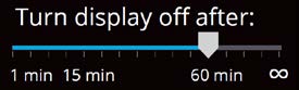
- On the Seakeeper 5” Touch Display only, there is a sleep timer. Adjust the sleep timer from 1 minute to infinite using sleep time slider. Touching the screen will wake the display up after it has gone to sleep. The MFD should be controlled within the MFD’s settings.
- If the Seakeeper is facing the bow of the vessel, the Roll Angle Gauge should show the blue on the left (pictured left). If the Seakeeper is facing the stern of the vessel, you should select the Roll Angle Gauge with the blue on the right (pictured right). A positive roll angle should be displayed when the vessel rolls to starboard.

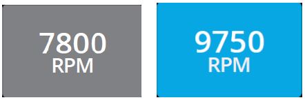
- Change the speed of the Seakeeper between normal operation and low power operation. Low power mode consumes less power and should generate less noise. The selected speed is colored blue. When power is cycled (or Seakeeper turned Off), this speed will default back to the normal operating speed.
- Change the display between day and night mode. The selected mode is colored blue and to change between day and night mode, press the button.

- Change the units of the temperatures displayed on the Service Page between degrees Celsius and degrees Fahrenheit. The selected units are colored blue.

Information Page
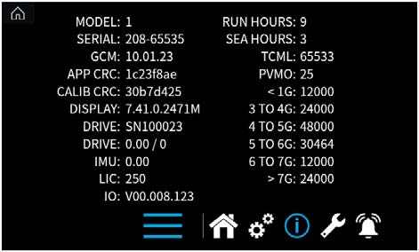
The Information Page ![]() displays the Seakeeper Model, Serial Number, Software Versions, Run Hours, Sea Hours, and other information. The image below is an example and may not match information details of installed Seakeeper.
displays the Seakeeper Model, Serial Number, Software Versions, Run Hours, Sea Hours, and other information. The image below is an example and may not match information details of installed Seakeeper.
Service Page
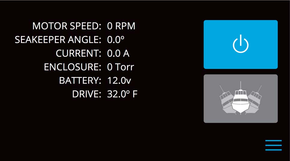
The Service Page ![]() displays Seakeeper operating information.
displays Seakeeper operating information.
Alarm History Page
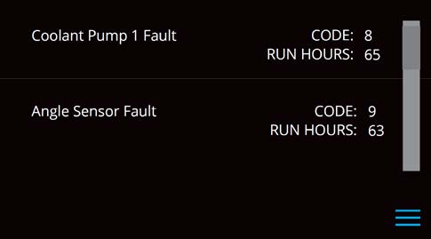
The Alarm History Page ![]() shows alarms and warnings that have occurred in the past and their associated run hours. The scroll bar on the right is used to move up and down through the list.
shows alarms and warnings that have occurred in the past and their associated run hours. The scroll bar on the right is used to move up and down through the list.
ConnectBox Overview
- The ConnectBox POWER button will pulse red if the Seakeeper causes an alarm. The alarm must be addressed on the Seakeeper Application.
- The BRIGHTNESS button on the ConnectBox will toggle through different brightness settings of the Seakeeper LED lights and the ConnectBox brightness. The ConnectBox and Seakeeper lights can be set independently of each other by turning off the SYNC BRIGHTNESS Button on the Seakeeper App.
- The WIRELESS button
 is reserved for future functionality and is disabled at this time.
Battery State of Charge Monitoring
Traditional batteries have a near-linear discharge voltage curve; new Lithium batteries do not have the same voltage curve. This characteristic makes it difficult to determine the Lithium battery charge state. Seakeepers have used battery voltage depletion to initiate power ramp-downs to extend battery life. With Lithium batteries, battery voltage is no longer an accurate indicator for this function; the state of charge (SoC) NMEA 2000 signal is more accurate when available.
Seakeeper software uses the NMEA 2000 State of Charge (SoC) signal to initiate a power ramp-down when an NMEA 2000 SoC signal is available on the network—the following guides in setting the Battery Monitoring Logic of the Seakeeper.
- Access battery monitoring configuration by one of the following methods:
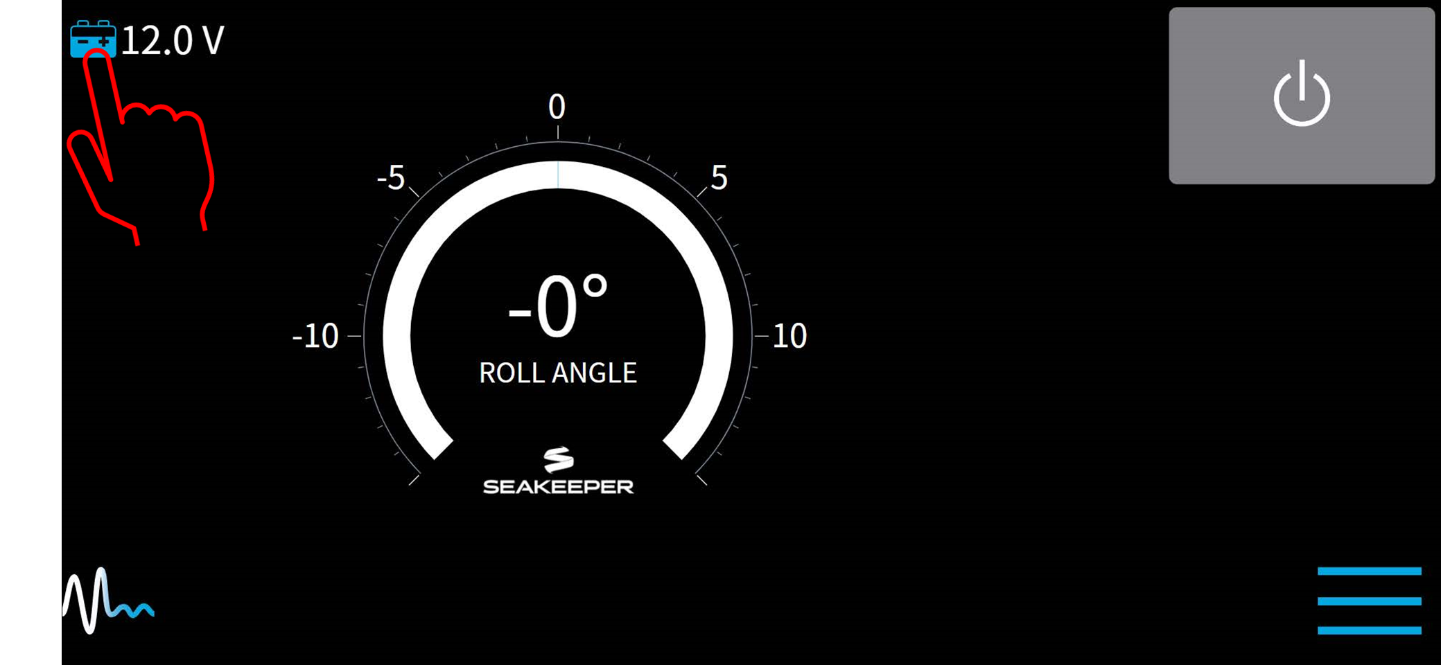
- Press and hold battery icon on home screen until configuration manager pop-up appears.
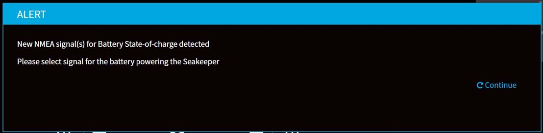
- From SoC alert pop-up , press CONTINUE.
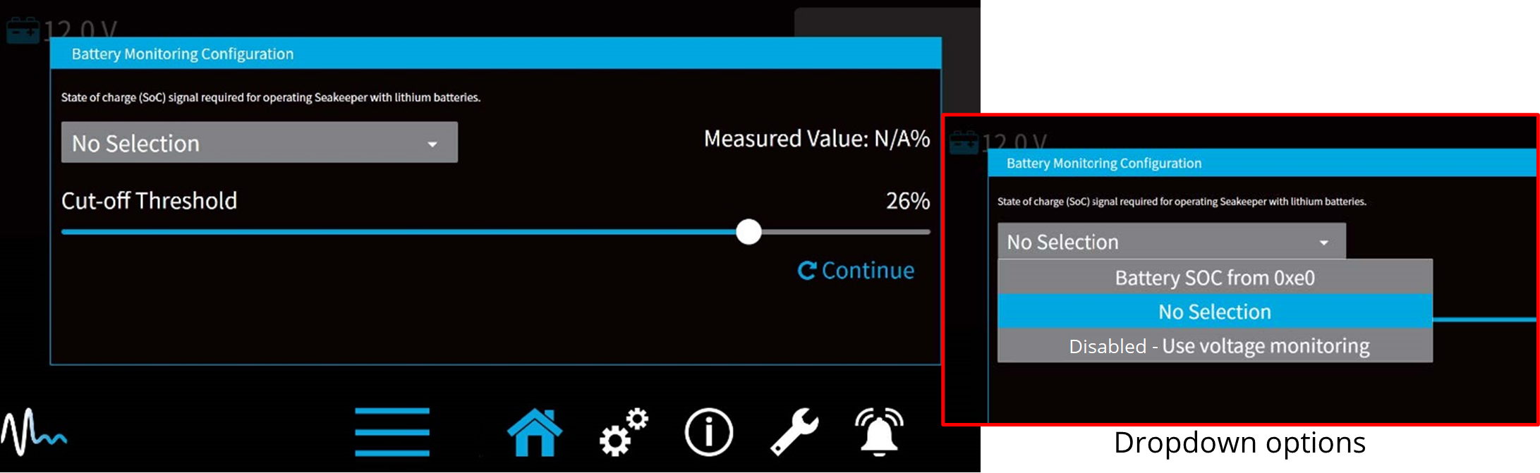
- On Battery Monitoring Configuration window, select the appropriate selection from the dropdown menu:
- No Selection – This is the default setting for the configuration manager.
- Disabled – Use voltage monitoring: This disables SoC logic and uses actual battery voltage to initiate powering back of the Seakeeper when battery voltage is low.
NOTE: If Seakeeper is NOT supplied by lithium batteries, this option should be selected. - Battery SoC from 0xE0 – This option allows the user interface to monitor the NMEA 2000 network for the battery state of charge from a battery management system monitoring the Seakeeper battery bank. (recommended if lithium batteries are used to power the Seakeeper).
When selected, the Cut-off threshold slider will determine at what battery charge the Seakeeper begins powering back to conserve battery power. Also, the 5” Touch Display will show battery state of charge in 20% increments beside the battery icon on the home screen (instead of a voltage). - Battery SoC from 0xE4, etc. – Lists all source addresses from which the NMEA SoC signal is received (Multiple battery management systems may exist; select only the battery monitor attached to the Seakeeper battery bank).
Start Up Instructions
Power On
- Energize Seakeeper 1 Battery Isolation Switch.
- Energize Seakeeper 1 High Current DC Power Supply (12 VDC, 80 A) at customer-supplied circuit breaker.
- Energize 12 VDC seawater pump power supply at the customer-supplied circuit breaker (unless a fuse is supplied as overcurrent protection).
- When the high DC power is turned on, the ConnectBox and Seakeeper 5” Touch Display and/or MFD application will initialize as seen below. The Seakeeper 1 can be powered on and controlled by either the Seakeeper Application or the ConnectBox.
- With system energized, check the Seakeeper display for any ALARMS. If there are any ALARMS present, they must be addressed to proceed.
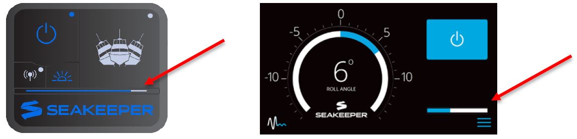
- To turn the Seakeeper on, press the POWER button; the button will turn blue. The progress bar will appear and indicate how soon the Seakeeper will be available for stabilization. The progress bar indicates the speed of the flywheel as it accelerates to its rated operating RPM.
- When the Seakeeper is initialized and up to Stabilization RPM the STABILIZE button will appear on the application, or if using the ConnectBox, the STABILIZE button will illuminate blue and pulsate. At this point, the Seakeeper is available for stabilization by pressing the STABILIZE button.

- The progress bar indicating flywheel spool-up will disappear from the display screen once the STABILIZE button is pressed (turns blue) and the ConnectBox will fully illuminate. At this point, the Seakeeper has reached its rated operating RPM and maximum stabilization is available. If the STABILZE button has not been pressed (button is grey), pressing the button will turn it blue and stabilization will be provided. The seawater pump will cycle on and off based on the operating temperature of the Seakeeper 1.

Stabilization
To stabilize the vessel after the Seakeeper is On and the flywheel is above the minimum stabilization RPM:
Press the STABILIZE button. The button will turn blue indicating that the Seakeeper is stabilizing the roll motion.
If it is necessary to shut off power to the flywheel motor and slow the flywheel for any reason, press Seakeeper On/Off button; the button will turn grey and the STABILIZE button will disappear, indicating the command has been accepted. It takes approximately 2+ hours for the speed to slow down to 0 RPM.
If it is necessary to stop Seakeeper motion for any reason press the STABILIZE button. The STABILIZE button will turn grey indicating that the Seakeeper is locked. Never attempt to work on the Seakeeper until the flywheel has stopped spinning. If the brake system has automatically locked the Seakeeper due to an alarm or failure, no attempt should be made to bypass the alarm or automatic lock.
Normal Shut Down
The Seakeeper should be shut down when stabilization is no longer required. This maximizes the longevity of the Seakeeper 1.
- Press the Seakeeper POWER button. The POWER button will turn grey. The Seakeeper will discontinue stabilization and the flywheel will start coasting.
- Once the vessel is secured in the slip, switch the high current (80 A circuit breaker) and low current (circuit breaker rated per seawater pump) DC power to the Seakeeper off. The flywheel will continue to spool down to 0 RPM. This can take 2+ hours from full speed. When the flywheel has stopped spinning, 0 RPM will appear on the service screen.
The Seakeeper should be stopped when stabilization is no longer required. Once the vessel is secured in the slip, the high and low current DC power to the Seakeeper should be switched to the Off position. The Seakeeper will continue to spool down to 0 RPM. No cooling is required during this time. Note Seakeeper will take 2+ hours to coast down to 0 RPM from full speed.
Note: The seawater pump may run for up to 5 minutes after the Seakeeper is switched off and is coasting (with low current DC power applied).