Seakeeper 40 Installation Manual (90715-1) 40-233-0001 - 40-234-0042
3.4 Operator Station
This section explains the connection between the Operator Station equipment and the Seakeeper.
Reference Documents & Drawings
3.4.1 Determine Location of Operator Station
- The desired location of the Operator Station must be determined with respect to the vessel arrangement.
- The operator display should be located on the bridge console.
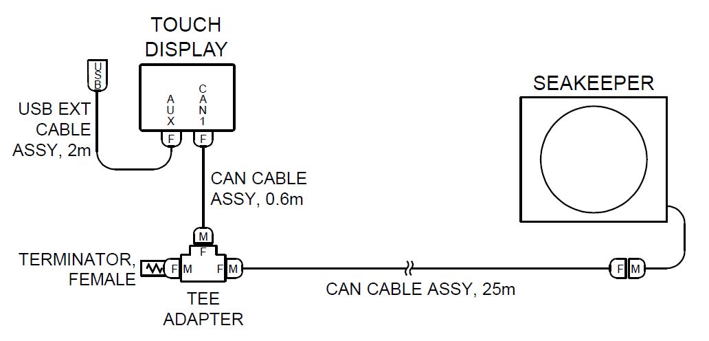
- Figure 9 below shows the CAN bus communications link for the Operator Station. The Terminator goes on the far end of the Tee Adapter from the Seakeeper.
3.4.2 Route Serial Communications Cable
- The CAN Cable Assembly (P/N 30332) is a 82 FT (25 m) shielded cable and the largest connector is a molded plug with maximum outer diameter of .58 in. (14.8 mm).
- The CAN Cable Assembly must be routed and installed in the vessel from the Seakeeper (female end) to the Tee Adapter (male end) at the Operator Station.
3.4.3 Install Operator Station Equipment
- The Operator Station equipment is installed at the selected location using instructions found in Section: Electrical Equipment Power Connections.
3.4.4 Connect Operator Station Equipment
- The Operator Station equipment is electrically connected in accordance with Drawing No. 90710 – Seakeeper 40 Cable Block Diagram.
3.4.5 Optional 2nd Operator Station
- The desired location of the 2nd Operator Station must be determined with respect to the 1st Operator Station and the vessel arrangement.
- Typical locations include:
- Flybridge
- Engine room
Determine Cabling Arrangement
- Figure 10 shows the entire serial communications link for the optional 2nd Operator Station. The Terminator must be installed on the Tee Adapter farthest from the Seakeeper.
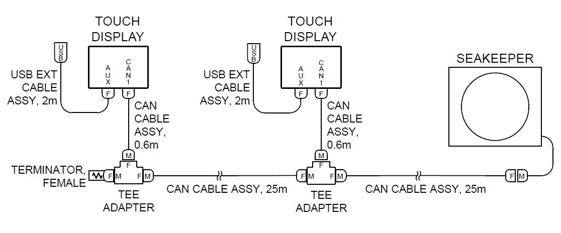
- The Operator Station nearest the Seakeeper should be connected to the CAN Cable Assembly.
Route 2nd Operator Station Cable
- A second CAN Cable Assembly (P/N 30332), also a 25 m shielded cable, and the largest connector is a molded plug with maximum outer diameter of .58 in. (14.8 mm).
- The additional CAN Cable Assembly must be routed in the vessel from the 1st Operator Station (female end) to the 2nd (male end) Operator Station.
Install 2nd Operator Station
- The 2nd Operator Station equipment is installed at the determined location using instructions found in Section: Electrical Equipment Mounting.
Connect 2nd Operator Station Equipment
- The 2nd Operator Station equipment is connected in accordance with Figure 10 and Drawing No. 90467 – Helm Display 2nd Operator Station.