Seakeeper 7.5 Installation Manual (90992-1)
2.3 Bolt-In Installation
2.3.1 Preparation of Vessel Structure
Seakeeper provided mounting hardware is intended to apply to typical installation arrangements. However, each installation, especially custom aftermarket foundations, should be thoroughly reviewed to ensure the provided hardware meets the required thread engagement for the Seakeeper unit being installed. The mounting bolt thread engagement requirements are outlined in the Installation Manuals and Installation Details Drawings for each Seakeeper model. This also applies to Seakeeper model adapter kits and OEM built frames where the bolt hole depth should be checked to ensure the bolts will not bottom, preventing the bolts from achieving the intended preload.
The Seakeeper supporting structure should be parallel to the vessel waterline, with up to 2 degrees allowance for trim.
In addition, the four areas on top of the beams on which the feet of the Seakeeper foundation and isolation gaskets will rest need to be co-planar within 0.06 in. (1.5 mm) to minimize potential distortion of Seakeeper support frame when installed. The isolation gaskets are only used when the Seakeeper 7.5 is mounted to a dissimilar metal structure.
When the Seakeeper provided hardware is not appropriate, the bolt specification (diameter and thread pitch) and grade should be matched in the required length and used with the Seakeeper provided washers. Mounting bolts should always be torqued to the Seakeeper specification. All Seakeeper provided bolts are metric course thread. Hardware specifications are also listed in the Installation Manuals and Installation Details Drawings.
Refer to Seakeeper Drawing No. 90989 – Seakeeper 7.5 Generic Installation Guide. Important dimensional and load information is given in this drawing that will impact the design details of the structure that will receive the Seakeeper. It is assumed that a proper structural analysis has been performed for the hull structure to which the Seakeeper will be fastened to ensure proper strength margins for the loads the Seakeeper will create during operation.
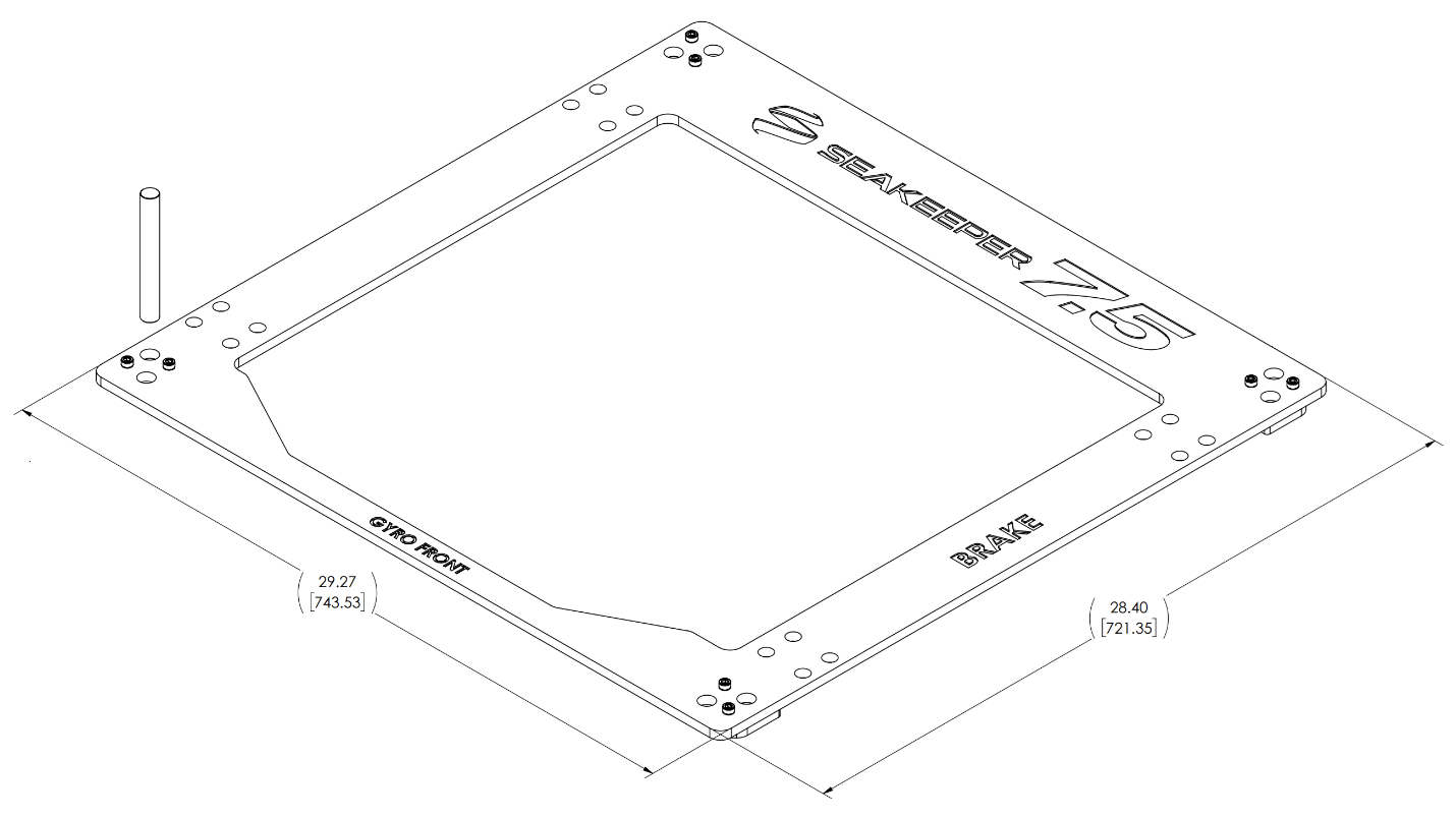
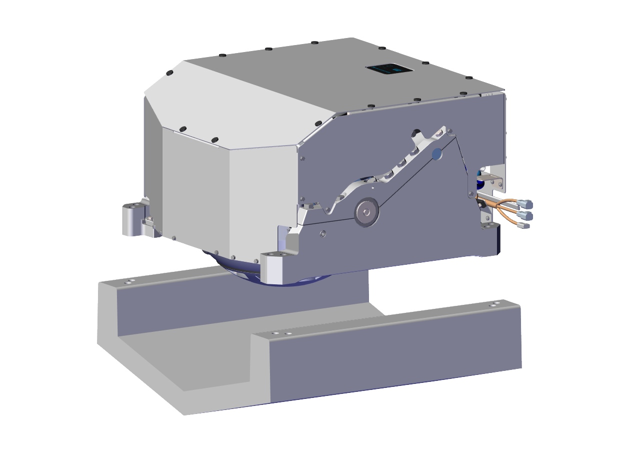
Seakeeper provides an installation template kit, P/N 90995, which contains four plates that mimic the mating surfaces of the four feet located on the Seakeeper’s foundation. These plates have holes located at the same centers as the mounting holes on the Seakeeper 7.5. The fixture locates the hole patterns at the proper spacing both in the forward-aft direction and the port-starboard direction. See Figure 8 below. Once assembled, the fixture can be used to check clearances and alignment of the hull structure.
Note: Do NOT use the installation fixture to establish Seakeeper envelope dimensions. Refer to Drawing No. 90998 – Seakeeper 7.5 Bolt-In Installation Details, for envelope dimensions. A 3-D model of the Seakeeper is available on the Seakeeper website (www.seakeeper.com) to aid in designing the Seakeeper foundation and the space around the Seakeeper.
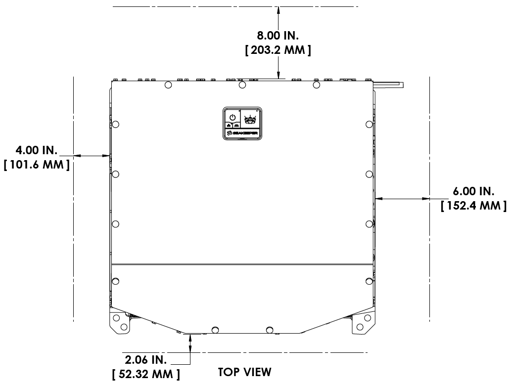
NOTE: MAKE SURE NO OBSTRUCTIONS FROM THE HULL STRUCTURE CAN BE SEEN WITHIN THE INSIDE OF THE INSTALLATION TEMPLATE KIT (INSIDE THE MARKED RED LINES). REFERENCE SEAKEEPER DRAWING NO. 90998 – SEAKEEPER 7.5 BOLT-IN INSTALLATION DETAILS.
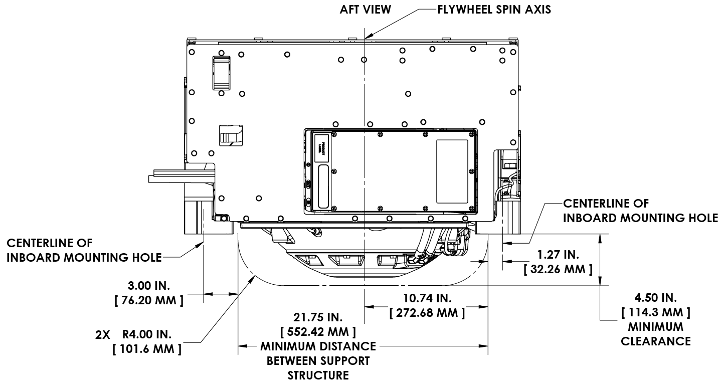
CAUTION: Tight clearances from cable guide bands and brake side gimbal shaft to hull structure. See below for brake side gimbal shaft clearance. See Figure 9 above for dimensions and reference Seakeeper Drawing No. 90998 – Seakeeper 7.5 Bolt-In Installation Details, for complete Seakeeper envelope.
2.3.2 Transfer of Holes to Boat Structure
- Lower assembled fixture onto hull structure.
- The four areas where the feet of the Seakeeper will rest should be coplanar to within 0.06 in. (1.5 mm). See Figure 11 below.
- Align fixture in desired location and transfer holes from fixture plate to the foundation structure. Note that holes in fixture plate are ø0.630 in. (16 mm). A transfer punch is supplied with installation template kit, P/N 90995.
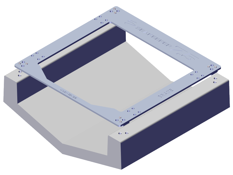
Figure 11 – Bolt-In Hole Transfer Fixture
2.3.2.1 Blind Hole Installation
These steps are for affixing tapping plates in the stringers. See drawing 90998 for details:
- Remove Template Fixture and drill eight (8) 0.650 in. (16.5 mm) holes perpendicular to the vessel structure to a minimum depth of 1.28 in. (32.5 mm). Take special care to drill perpendicular to mounting surface. A drill guide is recommended. Remove any impeding obstructions.
- Tap drilled holes for helical thread inserts (Fig. 12) per documentation accompanying helical threaded inserts (installer-supplied).
- Install eight (8) M16-2.0 X 24 mm threaded inserts into holes in hull structure at drilled and tapped locations using threaded insert manufacturer provided installation tool.
- Remove threaded insert prong / tang after threaded inserts are installed.
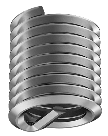
M16-2.0 X 24 mm
2.3.2.2 Through-Bolt Installation
- Remove Template Fixture and drill eight (8) 0.670 in. (17 mm) ø holes perpendicular to the vessel structure. Take special care to drill perpendicular to mounting surface. A drill guide is recommended.
2.3.3 Installation of Seakeeper
- For dissimilar metal foundations, locate and position four isolation gaskets (P/N 14306) (Fig. 15) onto foundation beams and apply a small bead of marine sealant (SILI-THANE 803 or equivalent) between both mating surfaces of each isolation gasket where it contacts the beam and the Seakeeper.
- Lower Seakeeper into position onto foundation beams and align over drilled holes.
- Install Mounting Bolts:
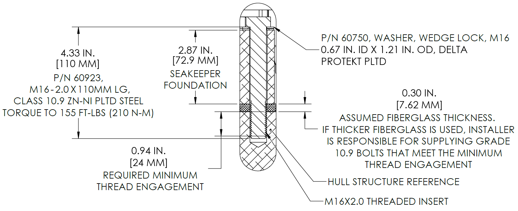
- For Blind-Hole installations (P/N 90911 – Seakeeper 7.5 Blind-Hole Installation Kit), install the Seakeeper supplied M16-2.0 fasteners to maintain a minimum thread engagement of 0.95 in. (24 mm). Apply a moderate coat of nickel-based anti-seize (e.g., SAF-T-EZE nickel grade anti-seize, SBT-4N or equivalent) to the threads of each bolt and include a small bead of marine grade sealant (e.g., SILI-THANE 803 or equivalent) under each bolt head and washer before installation. See Figure 14.
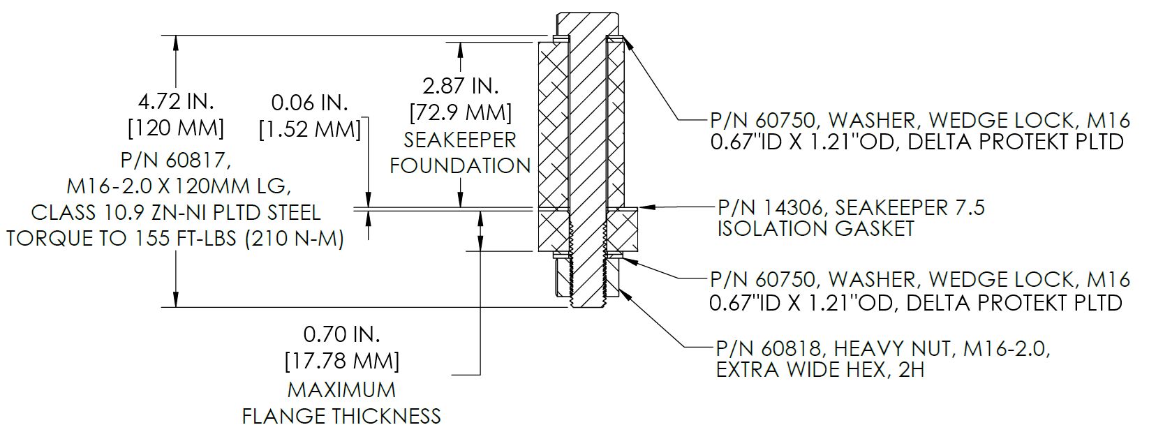
- For Through-Bolt installations (P/N 90912 – Seakeeper 7.5 Through-Bolt Installation Kit), install the Seakeeper supplied M16-2.0 fasteners to maintain a minimum of 2 threads protruding past nut. Apply a moderate coat of nickel-based anti-seize (e.g., SAF-T-EZE nickel grade anti-seize, SBT-4N or equivalent) to the threads of each bolt and include a small bead of marine grade sealant (e.g., SILI-THANE 803 or equivalent) under each bolt head and washer before installation. See Figure 15.
- Torque all fasteners to 155 ft-lbs (210 N-m).
- New bolts, matching the Seakeeper specification, must be used for each installation and reinstallation that meet the requirements listed above.
- Proceed to electrical and cooling portion of the installation.
3.0 Electrical Installation
3.1 Electrical Installation Introduction
This section for electrical installation explains how to mount the electrical equipment and how to connect the electrical cables.
Reference Documents & Drawings:
- 90951 – Seakeeper 7.5 Cable Block Diagram
- 90993 – Seakeeper 7.5 Operation Manual
- 90558 – ConnectBox Helm Mounting Kit
- TB-90640 – ConnectBox Connection Requirements
- Seakeeper MFD Compatibility Technical Bulletins
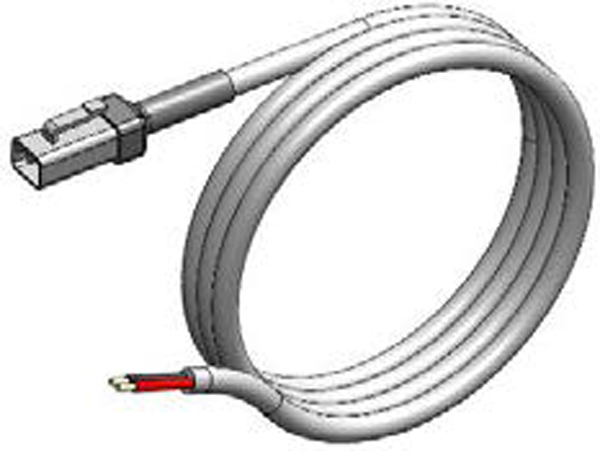
16.4 ft (5 m), P/N 20248
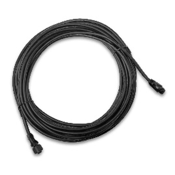
33 ft (10 m), P/N 30330
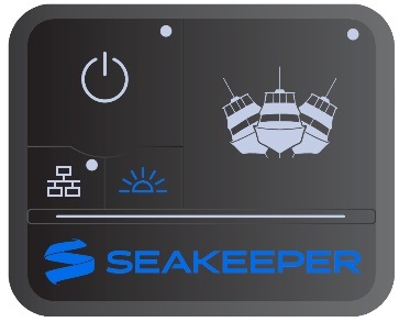
P/N 20415
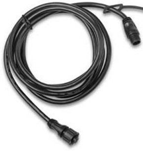
19.7 ft (6 m), P/N 30332
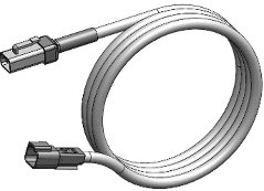
16.4 ft (5 m), P/N 20455
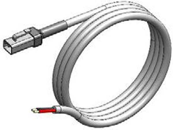
16.4 ft (5 m), P/N 20454
Figure 16 – Electrical Equipment for Seakeeper 7.5
3.2 Electrical Equipment Power Connections
AC Input Power Source Requirements
- Either of two AC input voltages are acceptable:
- 110 – 120 VAC (nominal) (+/- 10%), 1 Phase, 50/60 Hz, 30 A
- 208 – 230 VAC (nominal) (+/- 10%), 1 Phase, 50/60 Hz, 30 A
- A separate circuit breaker should be used for each Seakeeper drive in multiple Seakeeper installations.
Spool-Up Power Modes
The Seakeeper 7.5 is factory-configured for Default Spool mode, which accelerates the flywheel to operating speed (9700 RPM) in 24 minutes. This mode requires a higher AC power draw during startup (4000 W) but reduces the overall startup duration. For vessels with limited generator capacity or where minimizing peak electrical load is preferred, an optional Low-Power Spool mode can be selected on the display’s Settings page. This mode reduces the startup power demand to only 2300 W, which increases the time required for the flywheel to reach operating speed. Select the spool mode appropriate for the vessel’s electrical system to ensure reliable operation without overloading the AC power source.
Drive Box AC Power Input Connection Instructions
- Cable: 3 x 10 AWG (3 x 6mm2 CSA), 10 ft (3 m) length, Seakeeper supplied pre-installed.
- Locate AC Power Input Cable to the Drive at the outward of two cable glands per Figure 17.
- Connect AC wires to a 230 V, 30 A (or 110 V, 30 A), double-pole Circuit Breaker at an AC power distribution panel.
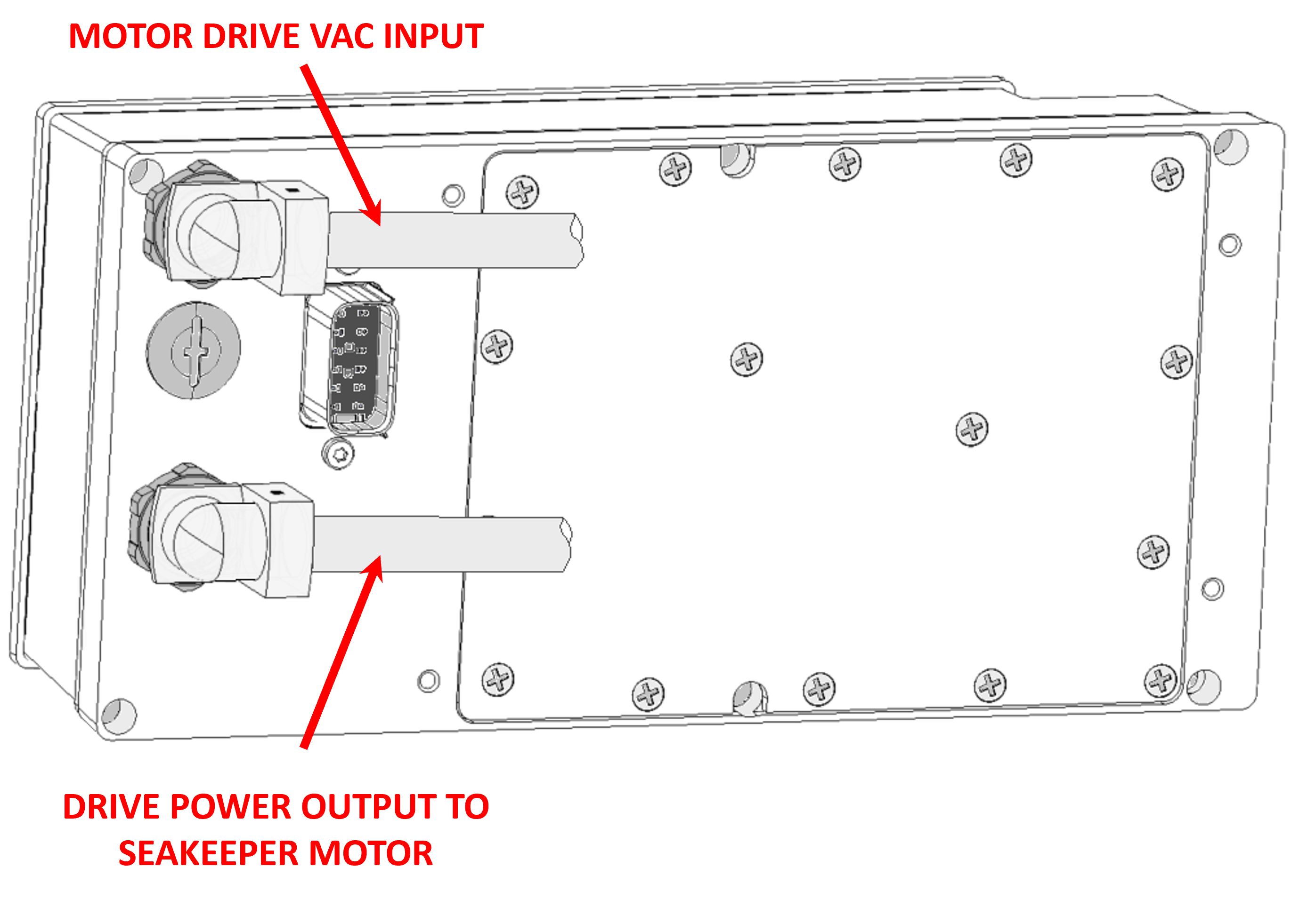
12 V Power Input
- One 12 VDC, 10 A (Customer supplied) for Seakeeper Control Power, AND
- One 12 VDC, 15 A (Customer supplied) for the DC Seawater Pump.
- A dedicated breaker should be used for Seakeeper control and Seawater Pump power for each Seakeeper unit.
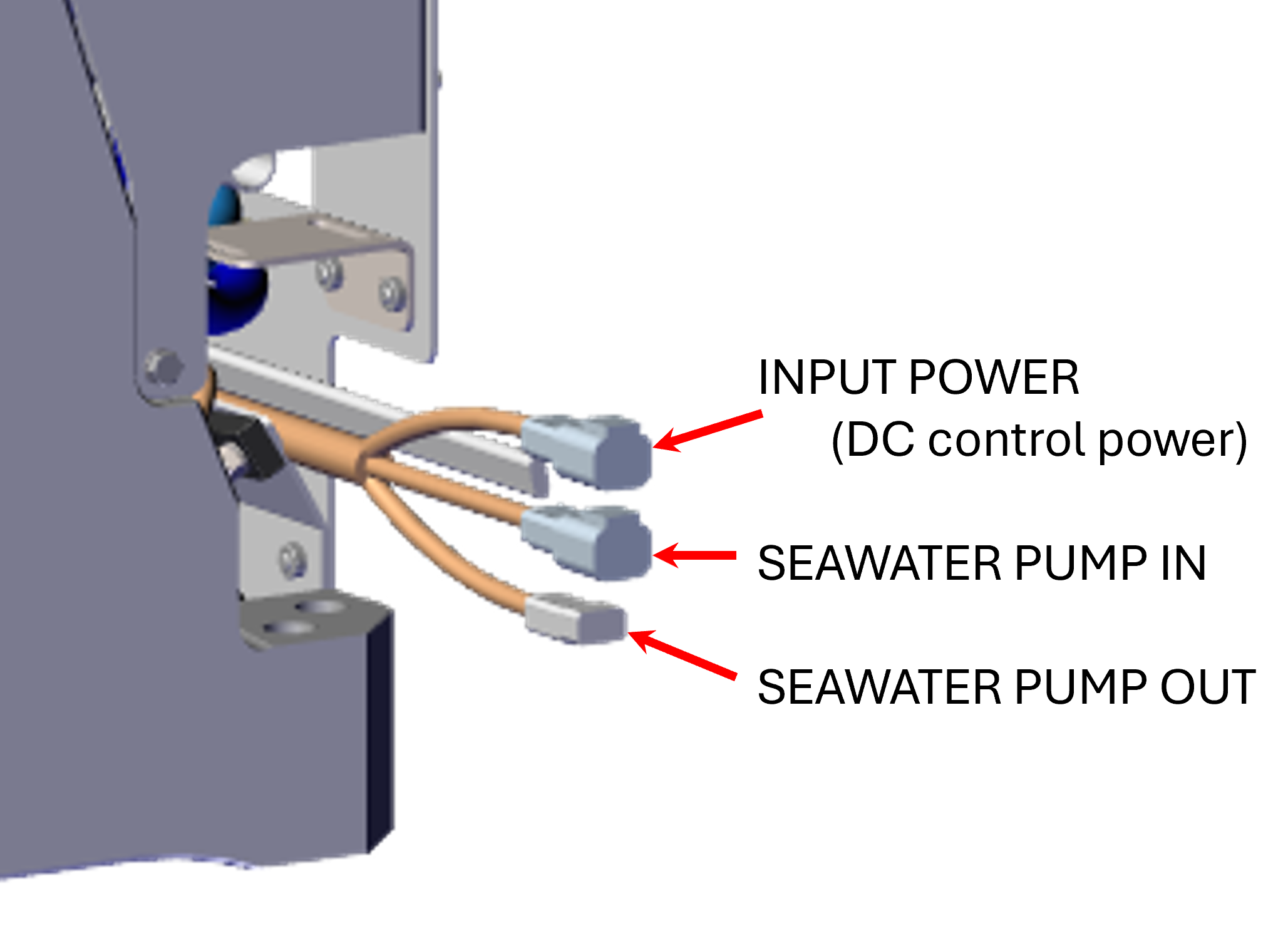
Seakeeper DC Control Power Connection Instructions

Reversing polarity on the DC power input to the Seakeeper can result in damaging the electronics in the control system.
- 12 VDC, 10 A, 2 x 12 AWG (3 x 4 mm2 CSA) customer supplied.
- Install Seakeeper provided DC Power Input Cable, P/N 20248 (shown in Drawing No.90951):
- Route DC Power Input Cable to DC Power Distribution Panel.
- Terminate positive (B+, Red) conductor through dedicated over-current protection device (customer supplied) and a dedicated Seakeeper isolation switch (customer supplied) then directly to battery plus terminal.
- Terminate negative (B-, Black) conductor directly to battery negative terminal or negative bus.
- Before connecting DC Power Input Cable to Seakeeper, check for proper voltage and polarity with a DC multimeter using Figure 19.
- Connect DC Power Input Cable to 12 VDC input receptacle on Seakeeper.
- Install Seakeeper provided DC Power Input Cable, P/N 20248 (shown in Drawing No.90951):
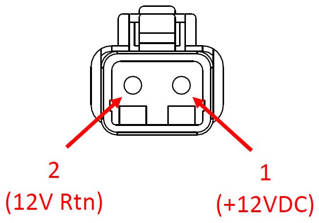
When energizing DC power the first time, if ConnectBox does not power up immediately then disconnect and inspect connector polarity.
DC Seawater Pump 12 VDC Power Input Connection Instructions
Connecting the DC Seawater pump in any other manner than recommended by Seakeeper may cause internal failure.
- Install DC SW Pump Input Power Cable (P/N: 20454) to Seakeeper 7.5 “SW Pump DC In” (shown in Drawing No. 90951) with overcurrent protection corresponding to seawater pump selected.
- Connect the 14 AWG positive conductor (red) through dedicated overcurrent protection device (customer-supplied), maximum of 15 A, to dedicated battery isolation switch.
- Connect the 14 AWG negative conductor (black) directly to battery negative terminal or DC main negative bus bar.
- Before connecting DC SW Pump Input Power Cable to Seakeeper, check for proper voltage and polarity with a DC multimeter using Figure 20.
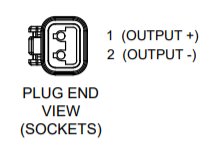
(Deutsch DTP04-2P)
- Connect DC SW Pump Power Input Cable to Seawater Pump 12 VDC In connector on the Seakeeper, DEUTSCH DT04-2P connector.
DC Seawater Pump 12 VDC Power Output Connection Instructions
- Connect DC SW Pump Power Output Cable (P/N 20455) to the Seakeeper 7.5 wire harness connector “SW Pump 12VDC Out” female connector for DC power output to the seawater pump.
- Seawater Pump Output Power Cable is a 2 x 14 AWG cable, 16 ft (5 m) length, with a size 14 female Deutsch plug.
- Pumps rated at 12 VDC, 15 A maximum, customer-supplied, must be configured with a Deutsch DTP series, 2-pin receptacle to mate with the connector shown in Figure 21.
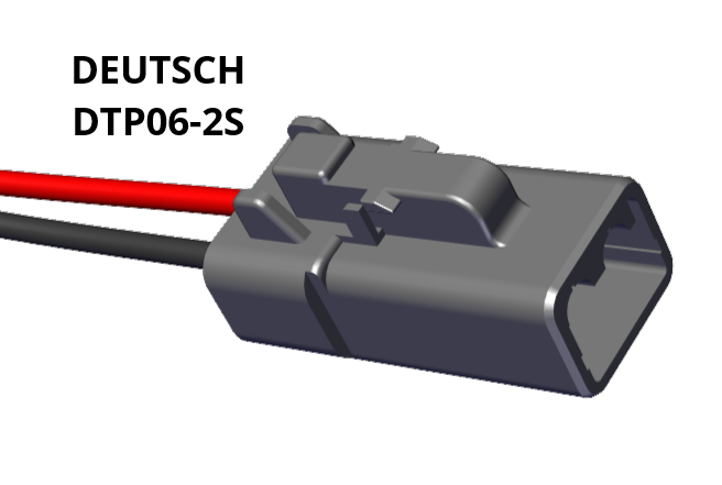
(Deutsch DTP06-2S)
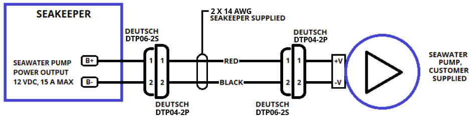
- The DC SW Pump Power Output Cable must be routed and installed in the vessel from the Seakeeper 7.5 “SW Pump 12VDC Out” Deutsch connector (pins end) to the customer-supplied seawater pump per Figure 22.
3.3 Electrical Equipment Ground Connections
Seakeeper to Vessel Ground Connection Instructions
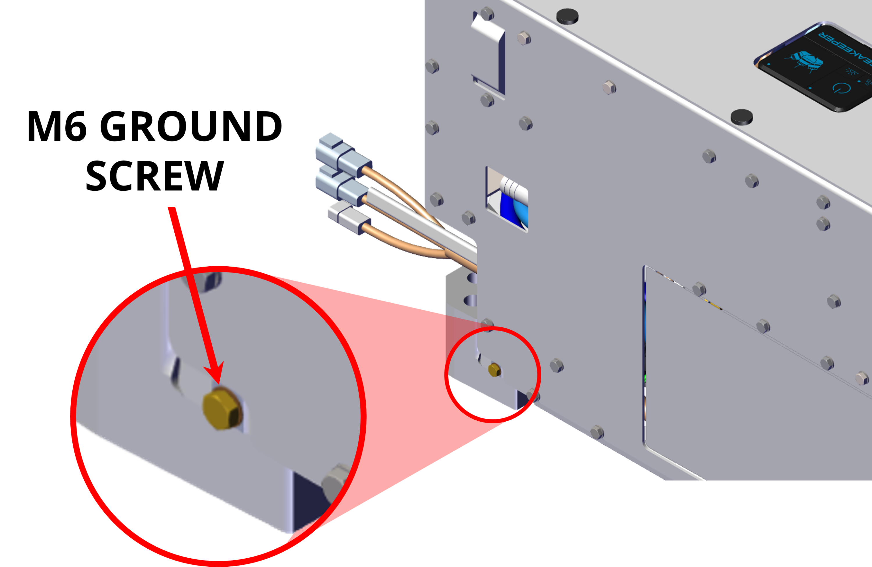
- Connect the Seakeeper foundation ground (Figure 23) to vessel ground.
- Install Ground Cable (10 AWG or 6.0 mm2, Customer supplied) from the M6 brass ground stud on the Seakeeper rear brace to a suitable vessel ground.
- EN/IEC 90204-1: 2016, Clauses 6.3.3 and 8.2.3
- ABYC E-11 July 2021, Clauses 11.5.2 and 11.17
NOTE: USE ONLY THIS LOCATION FOR GROUNDING THE SEAKEEPER TO THE VESSEL GROUND.
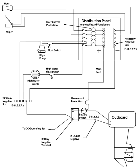
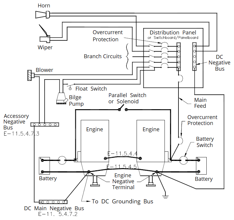
- Ground connection should be made with vessel bonding system, if available. However, the ground is not referring specifically to a bonding system but for outboard boats generally refers to the outboard engine negative terminal. Per ABYC E-11 (2018), Clause 11.5.2.7.4: If the negative side of the DC system is to be connected to the ground, the connection shall be made only from the engine negative terminal, or its bus, to the DC grounding bus. This connection shall be used only as a means of maintaining the negative side of the circuit at ground potential and is not to carry current under normal operating conditions.
- A proper ground connection is critically important for corrosion protection and helps to ensure the ignition protection of the unit by ensuring it does not carry any stray current.
3.4 ConnectBox Display Connections
Seakeeper 7.5 Display Options
A compatible multi-function display (MFD) is required with the installation of a Seakeeper 7.5 to support the full functionality of the unit through the Seakeeper App in addition to the ConnectBox. The Seakeeper App provides an interface for controlling the Seakeeper or viewing the Settings, Service, Info, and Alarm pages. The Seakeeper ConnectBox can be helm-mounted to provide an additional interface for the control of the Seakeeper but does not replace the need for a compatible display.
The Seakeeper 7.5 has several options for establishing a Seakeeper display interface to support the Seakeeper App:
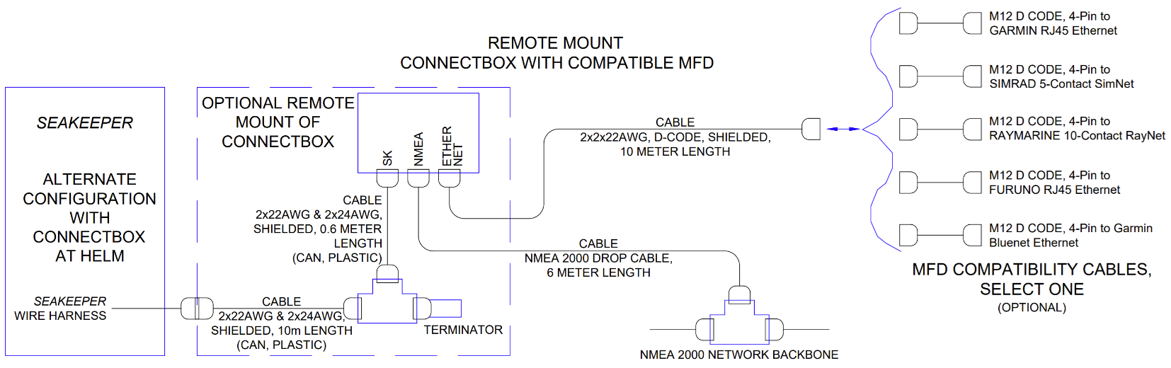
- Preferably, connect the Seakeeper to a compatible Multifunction Display (MFD) (Fig. 26).
- A combination of a compatible MFD with a remote-mounted ConnectBox is also available (Fig. 27).
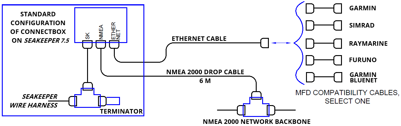
Figures 26 & 27 provide schematics of the preferred display options. The subsequent sections outline the instructions and references for connecting the Seakeeper 7.5 in each of these display options.
Connecting to a Compatible MFD
- The Seakeeper 7.5 can be connected to a variety of available MFD systems. Refer to the Technical Bulletins Section of the Seakeeper Technical Library for manufacturer specific MFD compatibility technical bulletins.
- MFD specific Technical Bulletins will be updated regularly as new MFD systems become compatible. Currently GARMIN, RAYMARINE, NAVICO (Simrad, Lowrance, B&G), and FURUNO offer compatible MFD models.
- Once a compatible MFD has been selected, refer to the appropriate manufacturer specific Technical Bulletin for integration instructions.
- Connect Seakeeper-supplied M12 D-Code, 32.8 ft (10 m), cable (P/N 30330) to MFD manufacturer-specific Ethernet adapter cable. Custom Ethernet cables for specific MFD manufacturers are available through Seakeeper and must be purchased with the Seakeeper 7.5 if connecting to an MFD.
- Daisy chains are allowed for the 4-pin D-Code Ethernet cables up to a maximum of 100 m in length.
- Seakeeper offers a 25 m length Ethernet cable (P/N 30355).
NOTE: The ethernet cable MUST be connected to the ConnectBox.
The Seakeeper 7.5 will not work properly if the ethernet cable is
connected to a Seakeeper 5″ Touch Display.
NMEA 2000 Network Connection
The Seakeeper 7.5 requires a connection to the vessel’s NMEA 2000 network backbone via a drop cable for access to the GPS signal. The Seakeeper 7.5 will monitor information on the NMEA network to support and optimize the performance of the Seakeeper 7.5. If no GPS signal is detected, a warning will appear on the Seakeeper display. The Seakeeper will not spool-down, but the operation of the unit will be limited until the GPS signal returns.
- Install customer-supplied NMEA 2000 Tee Adapter (space required: approximately 4 W X 3 H in. (102 X 76 mm).
- Connect NMEA Backbone to Tee Adapter.
NOTE: NMEA drop cable can be no longer than 19.6 ft (6 m) in length. - Connect Seakeeper-supplied NMEA cable (P/N: 30332) to the customer-supplied NMEA 2000 Tee Adapter on vessel’s NMEA 2000 backbone.
- An active NMEA 2000 compatible GPS signal is required on the vessel’s NMEA 2000 backbone to operate the Seakeeper 7.5.
- If no GPS signal is detected, a Speed Over Ground (SOG signal) warning will be present on the Seakeeper app. See TB-90640 for NMEA connectivity guidance.
- An active NMEA 2000 compatible GPS signal is required on the vessel’s NMEA 2000 backbone to operate the Seakeeper 7.5.
ConnectBox Helm Mounting – Optional
The ConnectBox helm mounting may be considered when replacing an earlier Seakeeper model with a 5″ Touch Display and connecting to a compatible MFD. This configuration eliminates the need to run an Ethernet cable from the Seakeeper to the MFD.
- Console space required: Approx. 3.41 L x 4.15 W in. (87 x 106 mm).
- Mounting Instructions, Surface Mount: Refer to Drawing No. 90558 – Seakeeper ConnectBox Helm Mounting Kit for details. Seakeeper ConnectBox 3D Model available upon request.
- Mount the ConnectBox Replacement Blank insert into the Seakeeper 7.5 top cover at the original location of the ConnectBox.
4.0 Cooling Installation
4.1 Cooling Installation Introduction
The Seakeeper 7.5 is shipped with the cooling circuit filled and ready for use. Only a quick confirmation of glycol level is required.
Reference Documents & Drawings:
- 30685 – Seakeeper DC Seawater Pump Assembly
- 90951 – Seakeeper 7.5 Cable Block Diagram
- 90952 – Seakeeper 7.5 Cooling Water Schematic
The Seakeeper 7.5 is shipped with the glycol cooling circuit filled and ready for use. The Seakeeper 7.5 requires connection to a raw water pump, referred to as the seawater pump, to cool the closed loop cooling circuit on the unit. The required seawater flow through the Seakeeper 7.5 heat exchanger is between 4.5 – 6 GPM (17 – 22.7 LPM) when the on-demand cooling system requires cooling. Prior to operation, confirmation of glycol level is recommended.
Seakeeper offers a compatible self-priming DC Seawater Pump (P/N 30685) prewired for the Seakeeper 7.5 Installation and covered under the standard Seakeeper warranty. Refer to Drawing No. 30685, SeaFlo® Seawater Pump Assembly, and the Seakeeper Options and Accessories Price List for details.
4.2 Installation Considerations
- The installer is responsible for supplying a dedicated seawater pump, an electric isolation valve, and associated plumbing. Seawater connections on the heat exchanger mate with ¾ in. (19 mm) hose. An optional seawater pump can be purchased from Seakeeper (P/N 30685).
- There is no need to disconnect the hose from the glycol pump except to replace the pump. In this case, provision will need to be made to catch the draining glycol, as the plumbing is disconnected. Use caution to avoid breaking plastic hose connections on the pump casing.
- The seawater pump is powered by the DC Seawater Pump Output cable on the Seakeeper 7.5, as outlined in the Electrical Installation Section 3.2.
- This pump must operate on 12 VDC, 15 A power. Pumps requiring other voltages or higher current can still be controlled by using this supply to trigger an installer-supplied contactor, but a separate power source must be provided.
- A dedicated through-hull fitting should be installed for each Seakeeper unit onboard the vessel to ensure sufficient seawater flow to each unit.
- It is recommended that the seawater pump be located below the waterline, as close to the vessel’s baseline as practically possible, to maintain positive inlet pressure on the pump in all operating conditions.
- A self-priming seawater pump is recommended to maintain water flow in all underway conditions. Cavitation can occur at the seawater inlet and potentially cause an air-lock condition restricting seawater flow to the heat exchanger.
- Vented loops are optional and should be considered only with centrifugal-style pumps. Self-priming or positive displacement style pumps do not require a vented loop; this includes Seakeeper P/N 30685.
- Maximum seawater pressure in the heat exchanger is 20 psi (1.4 bar)
- Seawater flow requirement through the heat exchanger is 4.5 GPM (17 LPM) minimum and 6 GPM (22.7 LPM) maximum under all operating conditions of the boat. When sizing the seawater pump, the installer should account for losses in the raw water plumbing. In addition to initial operation at the dock, new Seakeeper installations should be checked to ensure they meet flow requirements while the vessel is at speed. Flows above 6 GPM (22.7 LPM) could shorten heat exchanger life.
4.3 Connecting Seawater to Heat Exchanger
Connecting Seawater to Heat Exchanger
Refer to Figure 28 for typical seawater plumbing arrangement.
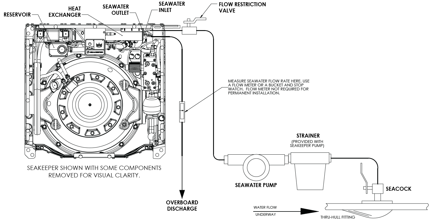
- Connect the seawater pump to the Seakeeper dedicated through-hull fitting. A seacock valve, and a strainer should be installed between the seawater inlet and the pump (See Figure 45).
- Connect seawater from the installer-supplied pump to the lower ¾ in. (19 mm) hose barb on the heat exchanger. Use the same practices as other below-waterline seawater plumbing. Required flow rate is 4.5 GPM (17 LPM) minimum and 6 GPM (22.7 LPM) maximum.
- Connect the seawater discharge (upper hose barb) to the overboard drain. It is recommended to install a visible flow meter in the discharge line, though it is not required for permanent installation. Use the same practices as other below-waterline seawater plumbing.
- In addition to initial operation at the dock, new installations should be checked for seawater flow while the vessel is at speed and when backing down. The flows should be recorded when the seawater pump is running and when it is off.
- If no other method of confirming flow is available, the discharge line may be temporarily diverted to a bucket. Flow is calculated from the time required to fill a known volume (e.g., a 5-gal. bucket).
- A self-priming seawater pump (customer/installer supplied) may be required at the installation location to maintain water flow in all underway conditions where cavitation may occur and potentially cause an air lock, restricting seawater flow to the heat exchanger.
- Inspect raw water plumbing after sea trial for any signs of leakage.
- The heat exchanger has removable end caps to provide access for cleaning the tube bundle.
Seakeeper Optional DC Seawater Pump (P/N 30685)
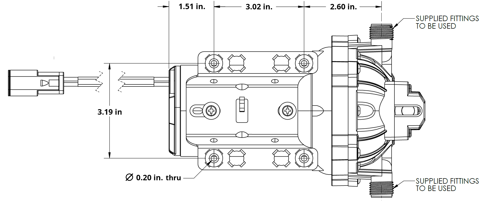
- Seakeeper offers a self-priming DC Seawater pump as an optional addition, P/N 30685– DC Seawater Pump Assembly, shown in Figure 29.
- The Seakeeper Seawater Pump is a 12 VDC pump.
- The pump assembly is pre-wired for connection to Seakeeper 7.5 “DC Seawater Pump Out” cable and includes a seawater strainer and various fittings. The pump specifications are as follows:
Note: Use only SeaFlo®-provided threaded fittings for DC Seawater Pump 30685.
| Volts | 12 VDC |
| Rated Flow | 5.5 GPM (20.8 LPM), maximum |
| Overcurrent Protection Rating | 15 A at 12 Volts |
| Ignition Protection | ISO 8846 or equivalent |
4.4 Adding Coolant
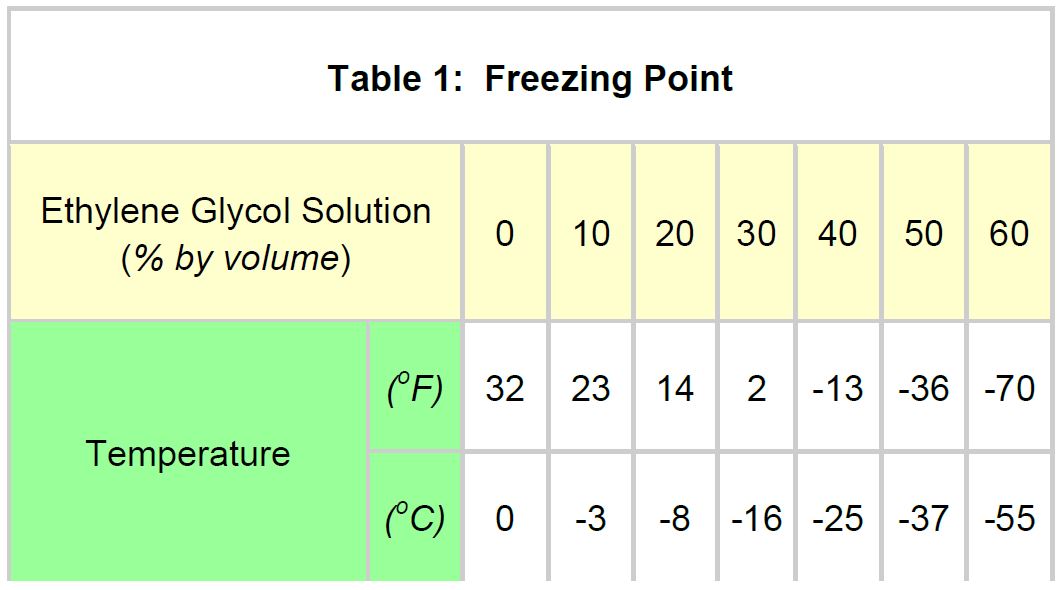
- Cooling system is filled to proper level when shipped, with a mixture of 50% ethylene glycol and 50% distilled water. The clear tube between heat exchanger and reservoir should be filled with green coolant mixture. If level has dropped, check for evidence of leaks at all connections before adding fluid as described below.
- Mix 50% ethylene glycol with 50% distilled water in a clean container. Refer to Table 1 or glycol manufacturer’s literature for freezing points.
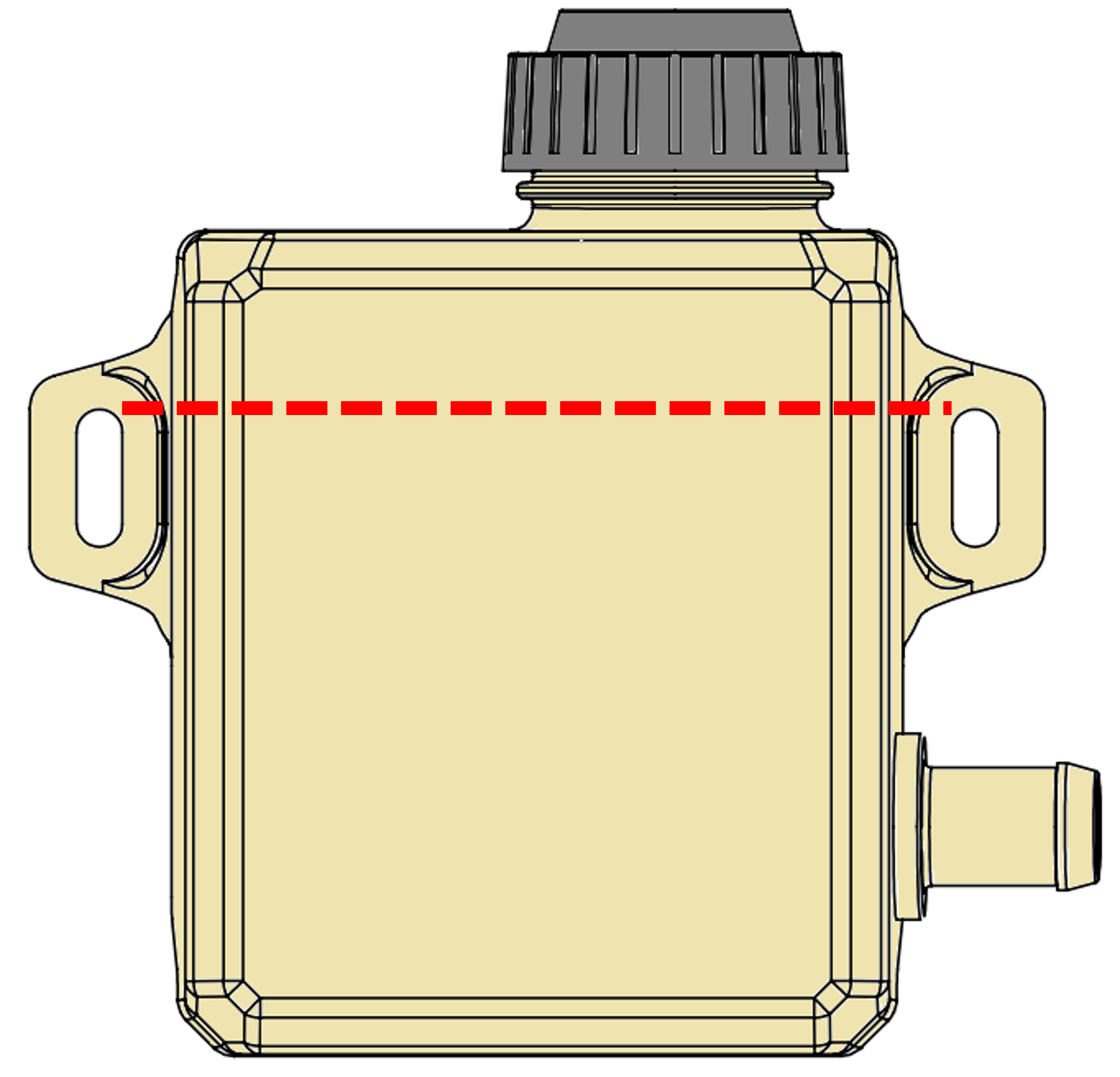
- Pour mixture in until level reaches top of reservoir as shown in Figure 30. Filling reservoir above this level will not cause any damage but coolant may be expelled from pressure relief port in cap due to normal thermal expansion of coolant.
- Connect 12 VDC to controller.
- At the display check for any ALARMS
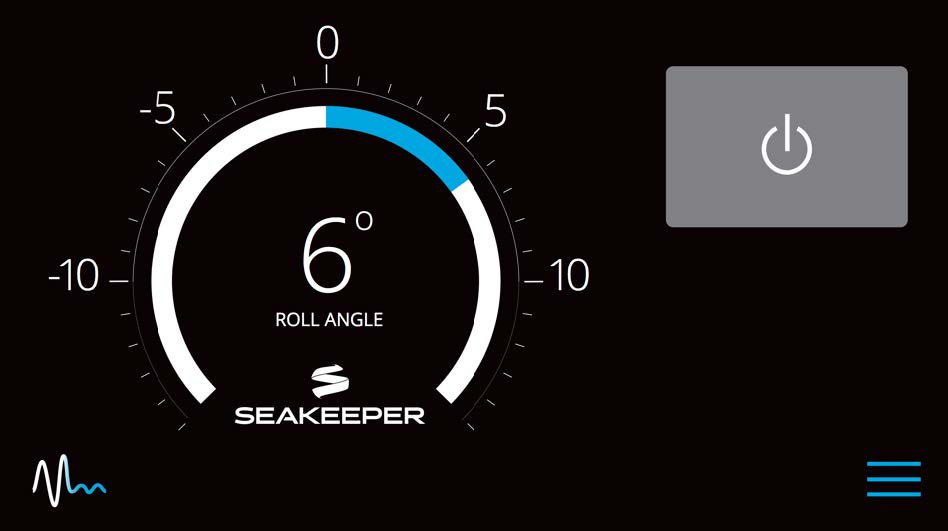
- Press the POWER ON/OFF button.

- The flywheel will start to spin and the glycol pump will start.
- Recheck glycol level with fluid circulating in coolant circuit. Sight reservoir and check that coolant level is above upper port on reservoir as shown in Figure 30.
- After several minutes of running, press POWER ON/OFF button
 to turn power off to the flywheel and glycol pump. The glycol pump will stop and the flywheel will coast to a stop.
- At the display check for any ALARMS
- The cooling system is self-purging. If small amounts of air are in the system, they will most likely be dislodged during the first sea trial. Re-check level after sea trial and add fluid if required.
5.0 Installation Requirements
5.1 Installation Requirements Introduction
The Installation Requirements section outlines the components and tools needed for the Seakeeper 7.5 installation that are not included within the scope of supply.
5.2 Required Supplies for Seakeeper Installation
Table 1 outlines the customer-supplied components required for the Seakeeper 7.5 installation:
| Item | Description | QTY | Installation Manual Reference Section | Other Reference | System |
| 1 | Spreader bar for lifting the Seakeeper | 1 | Transport & Unpacking | P/N 81885 | Mechanical |
| 2 | Seakeeper 7.5 Fixture Kit | 1 | Bolt-In Installation | P/N 90995 | Mechanical |
| 3 | Threaded insert M16-2 (24 mm) | 8 | Bolt-In Installation | Dwg 90998 | Mechanical |
| 4 | Seakeeper 7.5 Bolt-In Kit | 1 | Bolt-In Installation | P/N 90911 | Mechanical |
| 5 | Seakeeper 7.5 Thru-Bolt Kit | 1 | Bolt-In Installation | P/N 90912 | Mechanical |
| 6 | Marine Sealant | AR | Bolt-In Installation | Dwg 90998 | Mechanical |
| 7 | Nickel-based Anti-seize | AR | Bolt-In Installation | Dwg 90998 | Mechanical |
| 8 | Circuit Breaker 30 A, 110 VAC or Circuit Breaker 30 A, 230 VAC | 1 | Electrical Equipment Power Connections | Dwg 90951 | Electrical |
| 9 | Circuit Breaker, 12 VDC, 15 A | 2 | Electrical Equipment Power Connections | Dwg 90951 | Electrical |
| 10 | Battery Isolator Switch | 1 | Electrical Equipment Power Connections | Dwg 90951 | Electrical |
| 11 | M6 terminal lug for grounding Seakeeper | 1 | Electrical Equipment Ground Connections | Dwg 90951 | Electrical |
| 12 | Cable, 10 AWG, for grounding Seakeeper at rear brace to vessel ground | 1 | Electrical Equipment Ground Connections | Dwg 90951 ABYC E-11 | Electrical |
| 13 | Seawater pump, 12VDC, 15 A max Optional: DC Seawater Pump Assembly (pre-wired) | 1 | Electrical Equipment Power Connections | Dwg 90951 P/N 30685 | Electrical / Cooling |
| 14 | Compatible MFD | 1 | Electrical Equipment Power Connections | Dwg 90951 | Electrical |
| 15 | Through-hull fittings (1 high-speed pick-up / 1 overboard discharge) | 2 | Connecting Seawater to Heat Exchanger | Dwg 90952 | Cooling |
| 16 | Seawater Strainer *included with Seakeeper Seawater Pump (P/N 30685) | 1 | Connecting Seawater to Heat Exchanger | Dwg 90952 | Cooling |
| 17 | Seacock Valve | 1 | Connecting Seawater to Heat Exchanger | Dwg 90952 | Cooling |
| 18 | 3/4 in. (19 mm) ID Seawater Suction Hose AND Discharge Hose | AR | Connecting Seawater to Heat Exchanger | Dwg 90952 | Cooling |
| 19 | Hose clamps for seawater plumbing to ¾ in. (19 mm) hose barb (2 per hose barb) | AR | Connecting Seawater to Heat Exchanger | Dwg 90952 | Cooling |
AR = As Required
Dwg = Drawing
5.3 Tools Required for Installation
| Item | Description | Use |
| 1 | Wire Cutter | DC and AC power cables |
| 2 | Wire Stripper | DC and AC power cables |
| 3 | 10 and 13 mm Socket Wrench | Side Panels and ground stud |
| 4 | Slot Screwdriver, 5/64 in. | Field assembly connectors |
| 5 | 1/4 in. Nut Driver | Hose clamps |
| 6 | Greenlee K05-Synchro Crimp Tool, or equivalent | Ground cable |
| 7 | Utility Knife | Scoring cable jackets |
| 8 | Hoist, Forklift, or Crane | Unpacking and Lifting Seakeeper 7.5 into position |
| 9 | Drill/Drill Press | Bolt hole penetrations |
| 10 | 1/2 in. Drive Torque Wrench | Foundation bolt torqueing |
| 11 | 19 mm Socket Wrench | Foundation bolts |
| 12 | Heat Gun | For conductor heat shrink |
| 13 | Hole Saw | Through-hull seawater fittings |
6.0 Installation and Start Up Checklist
6.1 Checklists Introduction
Reference Documents:
- 90437 – Seakeeper Commissioning Form
- 90993 – Seakeeper 7.5 Operation Manual
- 90569 – Seakeeper ConnectBox and Application Quick Start Guide
The Installation and Start Up Checklist section provides an overview of the primary steps covered in the installation manual and should be referenced throughout the installation process. Upon completion of the
Seakeeper 7.5 installation, the installer should commission each Seakeeper unit with the Seakeeper Commissioning Form (90437).
All Seakeeper stabilizers should be commissioned to verify installation specifications and requirements have been implemented properly. The commissioning process should include completion of the Seakeeper
Commissioning Form (90437), all the items in the Installation Checklist, and verification of Seakeeper operation without alarms or abnormal behavior.
6.2 Installation Checklist
Please Complete Checklist and E-mail to support@seakeeper.com or emeasupport@seakeeper.com.
Mechanical Checklist
(Reference Installation Manual Section: Mechanical Installation)
- Seakeeper foundation installed in hull
- Foundation bolts torqued to specification
Electrical Checklist
(Reference Seakeeper Drawing No. 90951 – Seakeeper 7.5 Cable Block Diagram & Installation Manual Section: Electrical Installation)
Mount Components
- Display (near helm)
Connect Customer Supplied Cables
- Seakeeper Ground Cable (Customer Supplied)
- Install lugs on both ends of customer-supplied 10 AWG ground cable
- Connect one end of Cable 3 to nearest vessel ground and other end to Seakeeper rear brace
Connect Seakeeper Supplied Cables
- DC Control Power Input Cable (Seakeeper Supplied)
- Connect other end of cable to 12 VDC power at customer-supplied connection box or directly to circuit breaker
- Plug connector of cable into mating connector on Seakeeper wire harness
- DC Seawater Pump Input Cable (Seakeeper Supplied)
- Connect cable from SW PUMP VDC IN directly to circuit breaker
- DC Seawater Pump Output Cable and Y-Branch SW Pump & Valve Cable (Seakeeper Supplied)
- Connect cable from SW PUMP VDC OUT to Y-Branch SW Pump Output & Valve Cable.
- Connect customer-supplied DC seawater pump to Y-Branch SW Pump Output & Valve Cable.
- Connect inline fuse connector to DTM Deutsch connector and the electric ball valve to the inline fuse connector.
- Ethernet Cable (Seakeeper Supplied)
- Connect end of cable to mating connector on Seakeeper ConnectBox.
- Route Ethernet cable from Seakeeper to helm.
- Connect appropriate MFD-specific cable to end of Ethernet cable from ConnectBox.
- Connect Ethernet MFD-specific cable into compatible MFD or Ethernet bus.
- NMEA 2000 drop cable (Seakeeper Supplied)
- Attach NMEA 2000 drop cable to appropriate connector in ConnectBox.
- Connect other end of NMEA 2000 drop cable into NMEA backbone.
Cooling Checklist
(Reference Installation Manual Section: Cooling Installation)
- Verify glycol coolant level just below filler neck in heat exchanger coolant reservoir.
- Connect seawater hoses / open sea cocks to heat exchanger and test seawater pump.
- Verify 4.5 GPM (17 LPM) minimum and 6 GPM (22.7 LPM) maximum seawater flow through heat exchanger under all operating conditions of the boat.
Start Up Checklist
(Reference Installation Manual Section: Start Up & Operation Manual Section: System Operation)
- Remove lifting bolts and install cover panels
- Turn on 12 VDC circuit breakers (one for control power and one for 12 VDC SW Pump)
- Turn on 110 or 230 VAC circuit breaker
- Verify display works and no ALARMS are present
- Follow instructions in Installation Manual Section: Start Up Instructions to turn on the Seakeeper
- Verify seawater pump eventually turns on when the Seakeeper is ON
- Verify that no ALARMS are present
- Follow instructions in Installation Manual Section: Start Up Instructions to turn off the Seakeeper
- AC & DC power and seawater pump may be turned off after the Seakeeper is turned off by placing the Seakeeper in LOCK mode and turning the Seakeeper off
- Seakeeper may take 4 or more hours to coast down to 0 RPM from full speed
6.3 Start Up Checklist
Refer to Seakeeper 7.5 Operation Manual for detailed start up instructions.
Prior to beginning the start up sequence all previous Sections of the Installation Manual for Mechanical, Electrical, and Cooling installation must be complete.
Before continuing, the Seakeeper cover must be installed and the operating clearances must be clear of personnel and equipment.
| CHECK | REQUIREMENT TO BE MET |
| Remove lifting eyebolts and install sealing bolts and flat washers into lifting eyeholes and install top cover panels. | |
| Supply 110-230 VAC to Motor Drive Box at customer-supplied electrical disconnect. | |
| Energize 10 A control power and 15 A seawater pump breaker. | |
| Verify ConnectBox and MFD is active and no alarms present. | |
| Check that battery voltage exceeds 12 VDC. | |
| Override seawater pump “ON” for 5 seconds) and verify flow at seawater outlet. (To activate override, at 0 RPM flywheel speed, hold down SERVICE button wrench icon for 5 seconds to reveal override screen) | |
| Deactivate seawater pump when completed obtaining seawater flow rate. | |
| On the Settings screen (gears icon) of display, verify the correct spool power is selected (Default or Low-Power). | |
| Press Seakeeper ON/OFF Button and follow instructions in Seakeeper Operation Manual for complete start-up instructions. | |
| Verify no alarms are present. | |
| Power Seakeeper down, the Seakeeper flywheel will take 4+ hours to coast down to 0 RPM. |
7.0 Revision History
| REVISION | DESCRIPTION | DATE |
| 1 | Initial Release | 28SEP2026 |