Seakeeper 7.5 Installation Manual (90992-1)
6.2 Installation Checklist
Please Complete Checklist and E-mail to support@seakeeper.com or emeasupport@seakeeper.com.
Mechanical Checklist
(Reference Installation Manual Section: Mechanical Installation)
- Seakeeper foundation installed in hull
- Foundation bolts torqued to specification
Electrical Checklist
(Reference Seakeeper Drawing No. 90951 – Seakeeper 7.5 Cable Block Diagram & Installation Manual Section: Electrical Installation)
Mount Components
- Display (near helm)
Connect Customer Supplied Cables
- Seakeeper Ground Cable (Customer Supplied)
- Install lugs on both ends of customer-supplied 10 AWG ground cable
- Connect one end of Cable 3 to nearest vessel ground and other end to Seakeeper rear brace
Connect Seakeeper Supplied Cables
- DC Control Power Input Cable (Seakeeper Supplied)
- Connect other end of cable to 12 VDC power at customer-supplied connection box or directly to circuit breaker
- Plug connector of cable into mating connector on Seakeeper wire harness
- DC Seawater Pump Input Cable (Seakeeper Supplied)
- Connect cable from SW PUMP VDC IN directly to circuit breaker
- Connect cable from SW PUMP VDC IN directly to circuit breaker
- DC Seawater Pump Output Cable and Y-Branch SW Pump & Valve Cable (Seakeeper Supplied)
- Connect cable from SW PUMP VDC OUT to Y-Branch SW Pump Output & Valve Cable.
- Connect customer-supplied DC seawater pump to Y-Branch SW Pump Output & Valve Cable.
- Connect inline fuse connector to DTM Deutsch connector and the electric ball valve to the inline fuse connector.
- Ethernet Cable (Seakeeper Supplied)
- Connect end of cable to mating connector on Seakeeper ConnectBox.
- Route Ethernet cable from Seakeeper to helm.
- Connect appropriate MFD-specific cable to end of Ethernet cable from ConnectBox.
- Connect Ethernet MFD-specific cable into compatible MFD or Ethernet bus.
- NMEA 2000 drop cable (Seakeeper Supplied)
- Attach NMEA 2000 drop cable to appropriate connector in ConnectBox.
- Connect other end of NMEA 2000 drop cable into NMEA backbone.
Spool Power Mode Selection
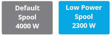
The Seakeeper 7.5’s factory-configured Default Spool mode reaches its 9700 RPM operating speed in 24 minutes using 4000 W during startup. Vessels with limited generator capacity can select Low-Power Spool mode on the display’s Settings page to reduce startup demand to 2300 W, although the flywheel will take longer to reach operating speed. The selected spool mode remains in effect after a power cycle. On the Settings screen, select the appropriate spool power mode.
Cooling Checklist
(Reference Installation Manual Section: Cooling Installation)
- Verify glycol coolant level just below filler neck in heat exchanger coolant reservoir.
- Connect seawater hoses / open sea cocks to heat exchanger and test seawater pump.
- Verify 4.5 GPM (17 LPM) minimum and 6 GPM (22.7 LPM) maximum seawater flow through heat exchanger under all operating conditions of the boat.
Start Up Checklist
(Reference Installation Manual Section: Start Up & Operation Manual Section: System Operation)
- Remove lifting bolts and install cover panels
- Turn on 12 VDC circuit breakers (one for control power and one for 12 VDC SW Pump)
- Turn on 110 or 230 VAC circuit breaker
- Verify display works and no ALARMS are present
- Follow instructions in Installation Manual Section: Start Up Instructions to turn on the Seakeeper
- Verify seawater pump eventually turns on when the Seakeeper is ON
- Verify that no ALARMS are present
- Follow instructions in Installation Manual Section: Start Up Instructions to turn off the Seakeeper
- AC & DC power and seawater pump may be turned off after the Seakeeper is turned off by placing the Seakeeper in LOCK mode and turning the Seakeeper off
- Seakeeper may take 4 or more hours to coast down to 0 RPM from full speed