Seakeeper 7.5 Installation Manual (90992-1)
2.0 Mechanical Installation
2.1 Mechanical Installation Introduction
The Seakeeper 7.5 is capable of producing loads up to 3795 lbs (16.88 kN) at each of the four mounts. These forces should be considered to be acting simultaneously, fully reversing, and will repeat an infinite number of times. Careful consideration should be given to foundation design to ensure it is capable of transferring these loads into the hull. These loads do NOT include vessel motion accelerations, such as vertical slam loads which can be significant for higher speed vessels. The responsible party for designing the supporting structure (boat builder, installer, or hired sub-contractor) must accommodate the above forces plus a reasonable factor of safety. Seakeeper recommends a minimum safety factor of 3.0 (yielding a Safety Margin of 2.0).
There are two methods of installing the Seakeeper 7.5:
1. Thru-Bolt-In Installation
2. Blind-Hole Installation
It is assumed that the installer is familiar with mechanical fastening to marine structures and has performed a structural analysis to assure the structure to which the Seakeeper mounts can properly transfer the loads the Seakeeper creates into the hull structure. If the installer has any doubt about the ability of the structure to transfer the loads to the hull then a licensed naval architect or marine engineer should be contacted to do a structural analysis.
The installer should review the following list of reference drawings to ensure the installation procedure is fully understood.
Reference Documents & Drawings:
2.2 Selection of Installation Location

Seakeeper can only assess installation location regarding its impact on Seakeeper operation and serviceability. Seakeeper cannot determine how the installation location will affect the vessel static or directional stability other than cyclic roll reduction. The Installer is responsible for considering the Seakeeper‘s effect on the CG location, trim, overall stability, and performance of the vessel.
Selection of mounting location of Seakeeper should consider the following desirable features:
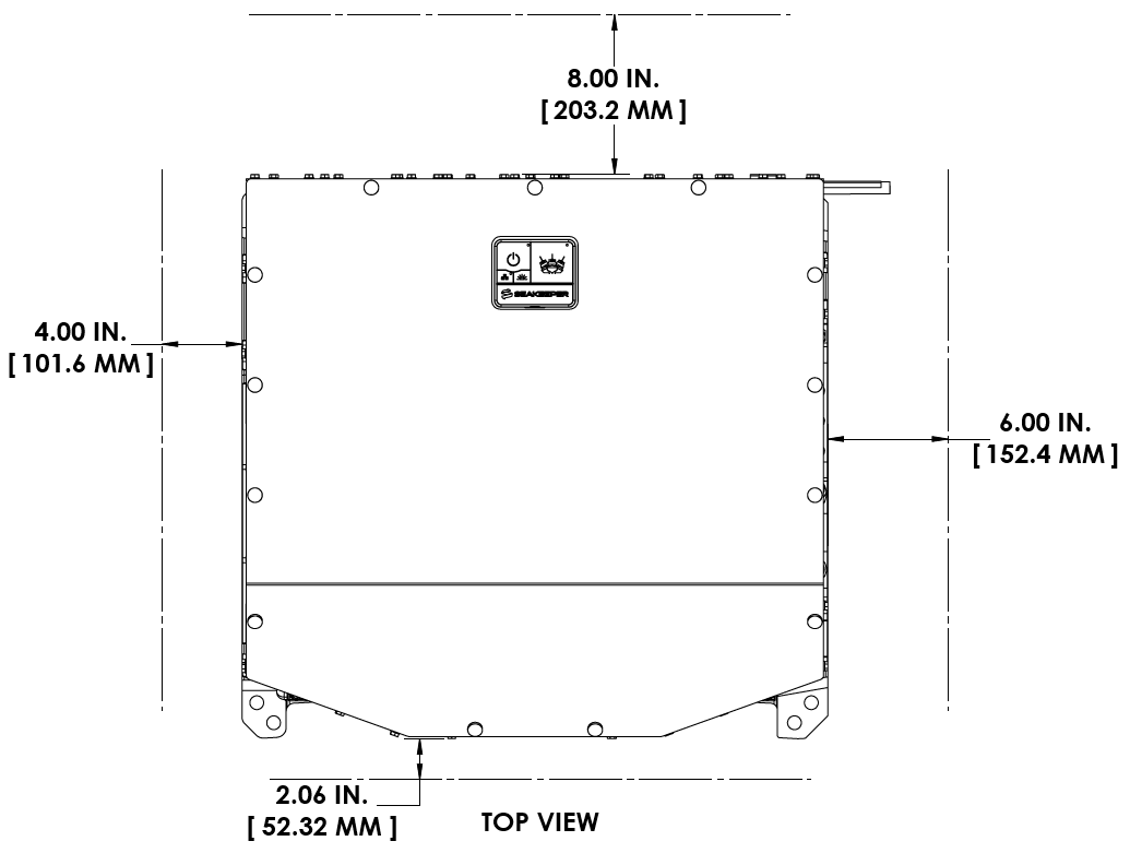
- Overhead access or sufficient clearance for removal / re-installation of the Seakeeper for overhaul in future years. Provide adequate clearance for maintenance, as shown in Figure 4 and 5 below.
- The Seakeeper should be installed in a dry space to minimize effects of corrosion.
- Installed near vessel’s longitudinal center of gravity (LCG) to minimize effects on trim and performance in various loading conditions.
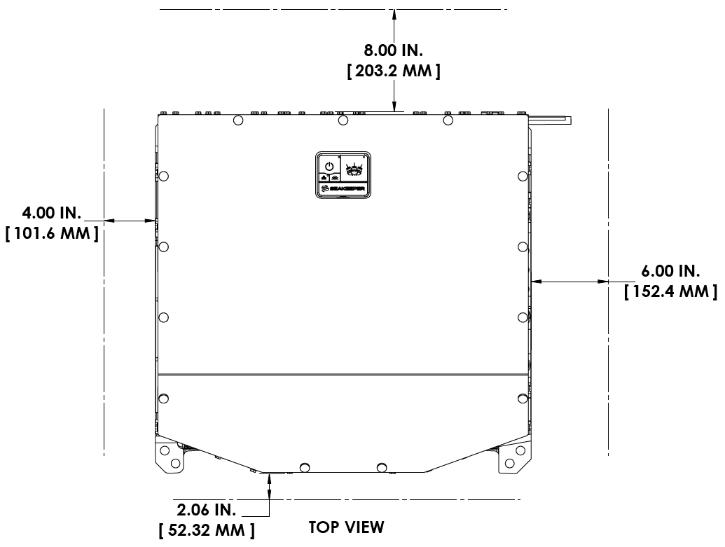
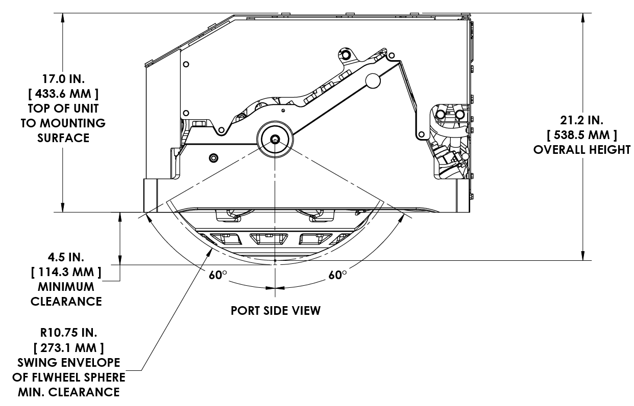
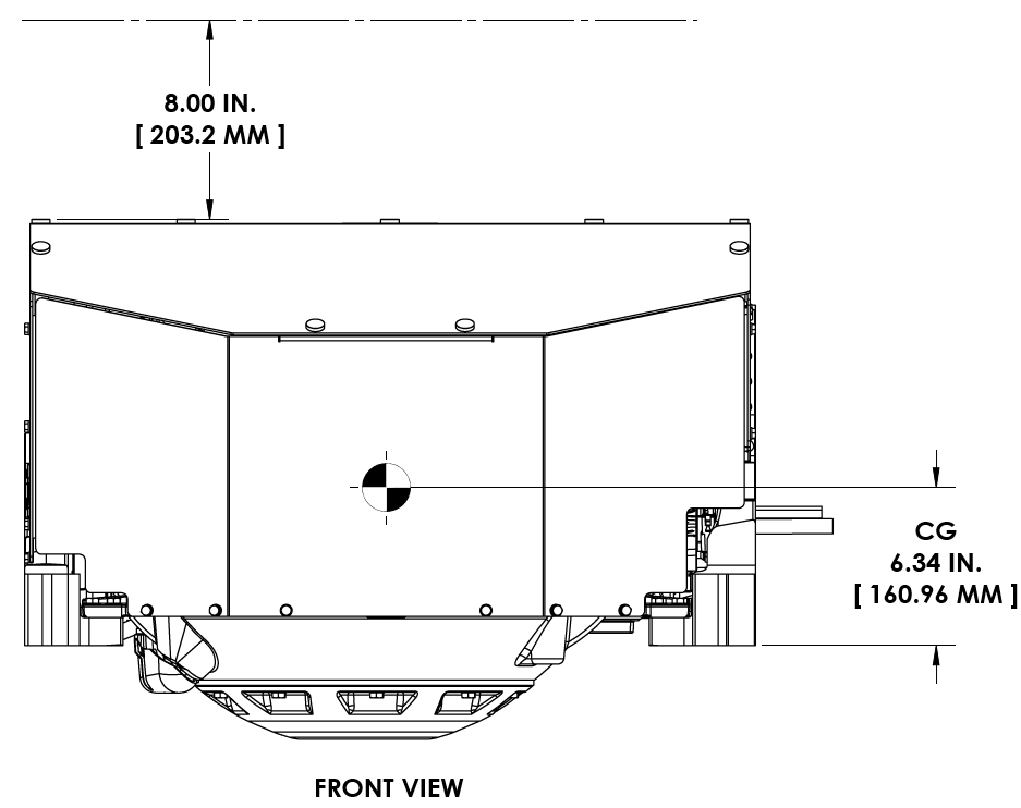
VIEWS SHOWING RECOMMENDED CLEARANCES AROUND THE SEAKEEPER FOR USE OF HANDTOOLS, EASE OF MAINTENANCE, INSTALLATION, AND PROPER OPERATION.
Figure 4 – Seakeeper 7.5 Installed Clearance Considerations
2.2.1 Noise/Soundproofing
Seakeeper noise has been measured under steady state conditions (no wave load) in Seakeeper‘s Engineering Lab and in our Factory Demo Boat. The steady state noise is typically <72 dBC at 1 meter. As the frequencies emitting the highest sound pressures are low (like other marine machinery), it is recommended that the Seakeeper be installed in a machinery space that is already treated with soundproofing.
2.3 Bolt-In Installation
2.3.1 Preparation of Vessel Structure
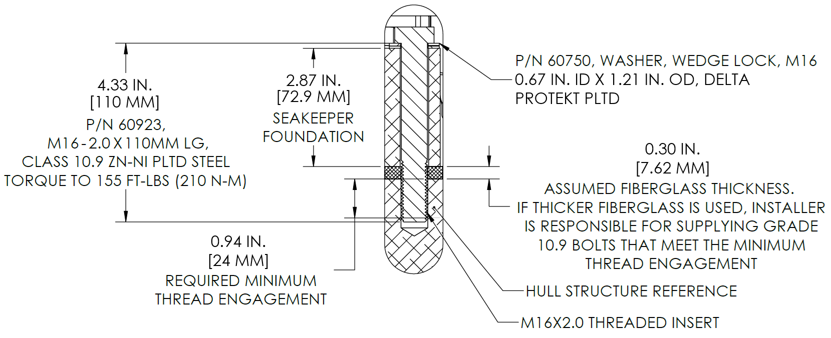
Seakeeper provided mounting hardware is intended to apply to typical installation arrangements. However, each installation, especially custom aftermarket foundations, should be thoroughly reviewed to ensure the provided hardware meets the required thread engagement for the Seakeeper unit being installed. The mounting bolt thread engagement requirements are outlined in the Installation Manuals and Installation Details Drawings for each Seakeeper model. This also applies to Seakeeper model adapter kits and OEM built frames where the bolt hole depth should be checked to ensure the bolts will not bottom, preventing the bolts from achieving the intended preload.
The Seakeeper supporting structure should be parallel to the vessel waterline, with up to 2 degrees allowance for trim.
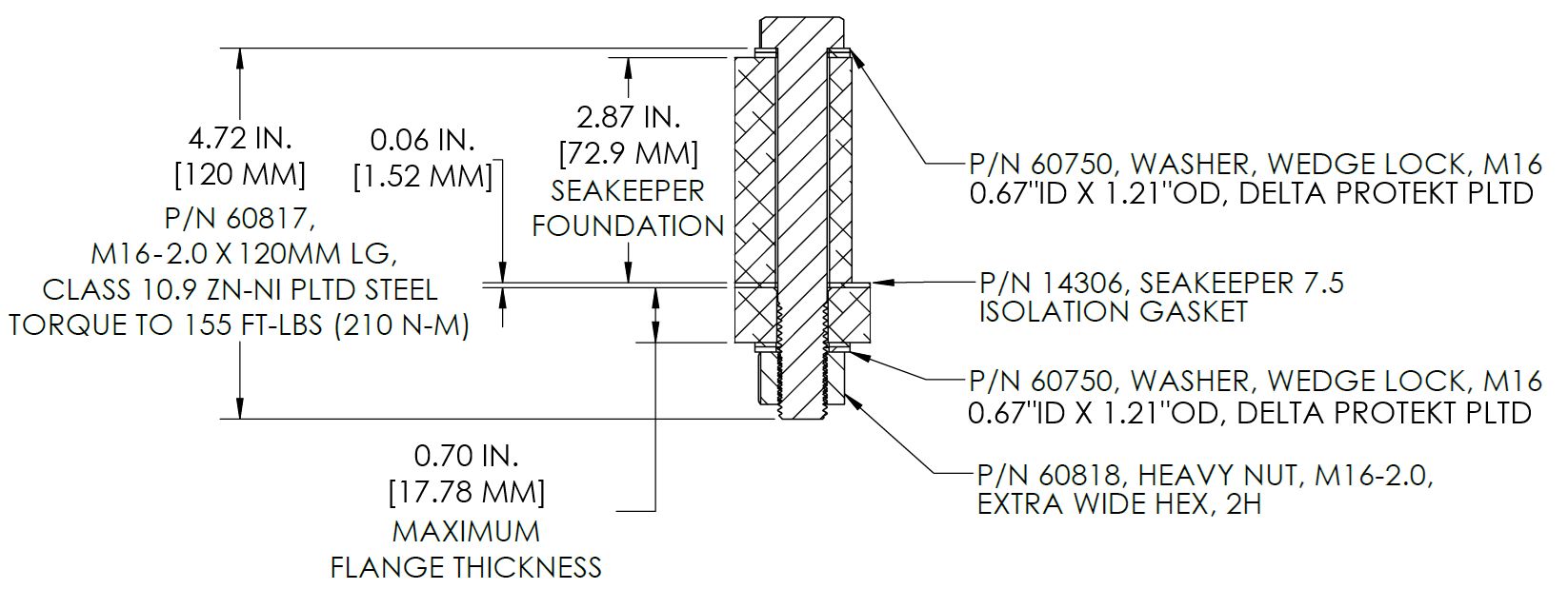
In addition, the four areas on top of the beams on which the feet of the Seakeeper foundation and isolation gaskets will rest need to be co-planar within 0.06 in. (1.5 mm) to minimize potential distortion of Seakeeper support frame when installed. The isolation gaskets are only used when the Seakeeper 7.5 is mounted to a dissimilar metal structure.
When the Seakeeper provided hardware is not appropriate, the bolt specification (diameter and thread pitch) and grade should be matched in the required length and used with the Seakeeper provided washers. Mounting bolts should always be torqued to the Seakeeper specification. All Seakeeper provided bolts are metric course thread. Hardware specifications are also listed in the Installation Manuals and Installation Details Drawings.
Refer to Seakeeper Drawing No. 90989 – Seakeeper 7.5 Generic Installation Guide. Important dimensional and load information is given in this drawing that will impact the design details of the structure that will receive the Seakeeper. It is assumed that a proper structural analysis has been performed for the hull structure to which the Seakeeper will be fastened to ensure proper strength margins for the loads the Seakeeper will create during operation.
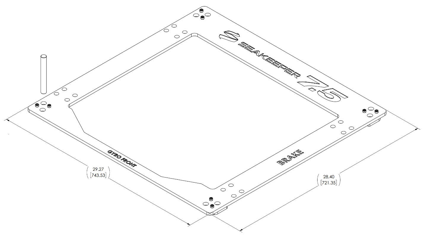
Seakeeper provides an installation template kit, P/N 90995, which contains four plates that mimic the mating surfaces of the four feet located on the Seakeeper’s foundation. These plates have holes located at the same centers as the mounting holes on the Seakeeper 7.5. The fixture locates the hole patterns at the proper spacing both in the forward-aft direction and the port-starboard direction. See Figure 8 below. Once assembled, the fixture can be used to check clearances and alignment of the hull structure.
Note: Do NOT use the installation fixture to establish Seakeeper envelope dimensions. Refer to Drawing No. 90998 – Seakeeper 7.5 Bolt-In Installation Details, for envelope dimensions. A 3-D model of the Seakeeper is available on the Seakeeper website (www.seakeeper.com) to aid in designing the Seakeeper foundation and the space around the Seakeeper.
NOTE: MAKE SURE NO OBSTRUCTIONS FROM THE HULL STRUCTURE CAN BE SEEN WITHIN THE INSIDE OF THE INSTALLATION TEMPLATE KIT (INSIDE THE MARKED RED LINES). REFERENCE SEAKEEPER DRAWING NO. 90998 – SEAKEEPER 7.5 BOLT-IN INSTALLATION DETAILS.
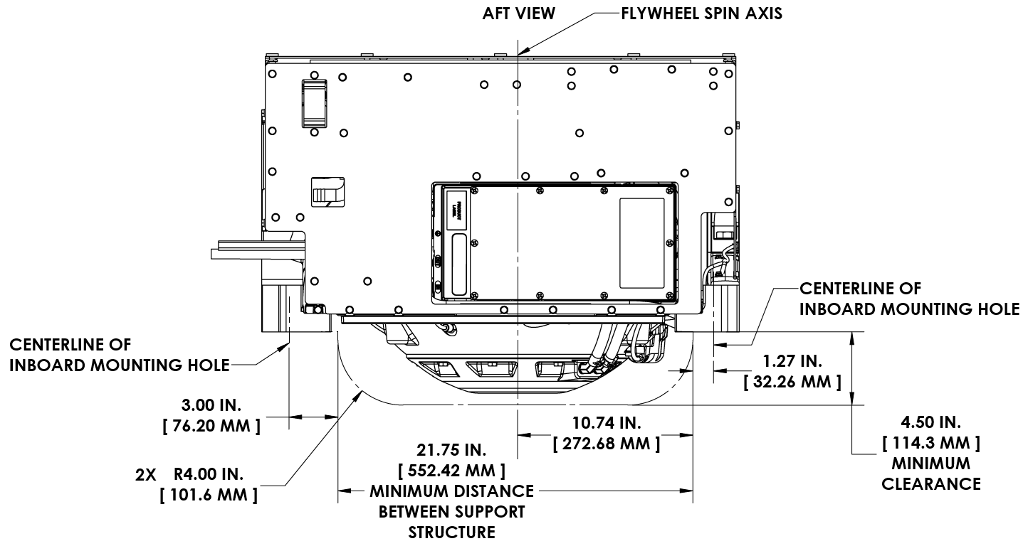
CAUTION: Tight clearances from cable guide bands and brake side gimbal shaft to hull structure. See below for brake side gimbal shaft clearance. See Figure 9 above for dimensions and reference Seakeeper Drawing No. 90998 – Seakeeper 7.5 Bolt-In Installation Details, for complete Seakeeper envelope.
2.3.2 Transfer of Holes to Boat Structure
- Lower assembled fixture onto hull structure.
- The four areas where the feet of the Seakeeper will rest should be coplanar to within 0.06 in. (1.5 mm). See Figure 11 below.
- Align fixture in desired location and transfer holes from fixture plate to the foundation structure. Note that holes in fixture plate are ø0.630 in. (16 mm). A transfer punch is supplied with installation template kit, P/N 90995.
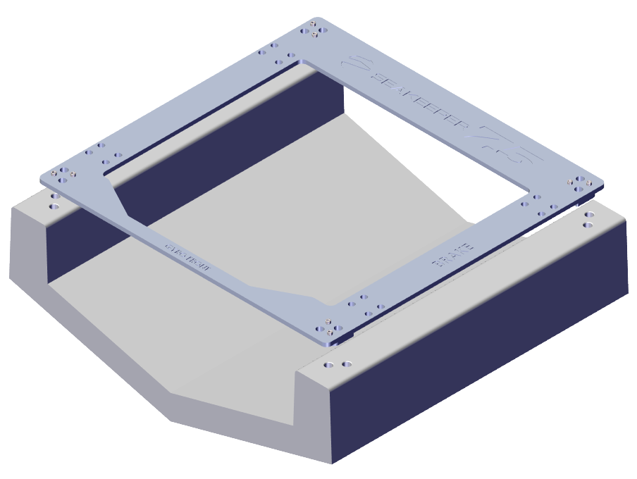
Figure 11 – Bolt-In Hole Transfer Fixture
2.3.2.1 Blind Hole Installation
These steps are for affixing tapping plates in the stringers. See drawing 90998 for details:
- Remove Template Fixture and drill eight (8) 0.650 in. (16.5 mm) holes perpendicular to the vessel structure to a minimum depth of 1.28 in. (32.5 mm). Take special care to drill perpendicular to mounting surface. A drill guide is recommended. Remove any impeding obstructions.
- Tap drilled holes for helical thread inserts (Fig. 12) per documentation accompanying helical threaded inserts (installer-supplied).
- Install eight (8) M16-2.0 X 24 mm threaded inserts into holes in hull structure at drilled and tapped locations using threaded insert manufacturer provided installation tool.
- Remove threaded insert prong / tang after threaded inserts are installed.
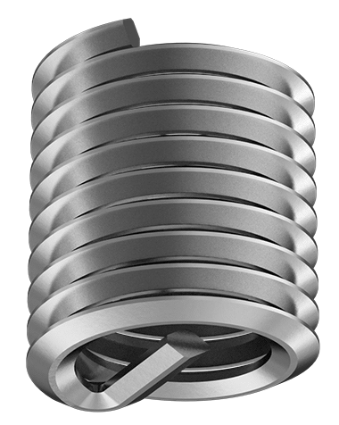
M16-2.0 X 24 mm
2.3.2.2 Through-Bolt Installation
- Remove Template Fixture and drill eight (8) 0.670 in. (17 mm) ø holes perpendicular to the vessel structure. Take special care to drill perpendicular to mounting surface. A drill guide is recommended.
2.3.3 Installation of Seakeeper
- For dissimilar metal foundations, locate and position four isolation gaskets (P/N 14306) (Fig. 15) onto foundation beams and apply a small bead of marine sealant (SILI-THANE 803 or equivalent) between both mating surfaces of each isolation gasket where it contacts the beam and the Seakeeper.
- Lower Seakeeper into position onto foundation beams and align over drilled holes.
- Install Mounting Bolts:
- For Blind-Hole installations (P/N 90911 – Seakeeper 7.5 Blind-Hole Installation Kit), install the Seakeeper supplied M16-2.0 fasteners to maintain a minimum thread engagement of 0.95 in. (24 mm). Apply a moderate coat of nickel-based anti-seize (e.g., SAF-T-EZE nickel grade anti-seize, SBT-4N or equivalent) to the threads of each bolt and include a small bead of marine grade sealant (e.g., SILI-THANE 803 or equivalent) under each bolt head and washer before installation. See Figure 14.
- For Through-Bolt installations (P/N 90912 – Seakeeper 7.5 Through-Bolt Installation Kit), install the Seakeeper supplied M16-2.0 fasteners to maintain a minimum of 2 threads protruding past nut. Apply a moderate coat of nickel-based anti-seize (e.g., SAF-T-EZE nickel grade anti-seize, SBT-4N or equivalent) to the threads of each bolt and include a small bead of marine grade sealant (e.g., SILI-THANE 803 or equivalent) under each bolt head and washer before installation. See Figure 15.
- Torque all fasteners to 155 ft-lbs (210 N-m).
- New bolts, matching the Seakeeper specification, must be used for each installation and reinstallation that meet the requirements listed above.
- Proceed to electrical and cooling portion of the installation.